key FIAT DUCATO BASE CAMPER 2018 Owner handbook (in English)
[x] Cancel search | Manufacturer: FIAT, Model Year: 2018, Model line: DUCATO BASE CAMPER, Model: FIAT DUCATO BASE CAMPER 2018Pages: 304, PDF Size: 14.93 MB
Page 135 of 304
REFUELLING THE
VEHICLE
IN BRIEF
Stop the engine before refuelling.
PETROL ENGINES
Only usepetrol with an octane number
(RON) no lower than 95 (EN228
specification).
DIESEL ENGINES
Refuel the vehicle exclusively with diesel
for motor vehicles in compliance with
European specification EN590.
OPERATION AT LOW
TEMPERATURES
When using or parking the vehicle for a
long time in the mountains or cold
areas, it is advisable to refuel using
locally available diesel fuel. In this case,
it is also advisable to keep the tank
over 50% full.
35)
TANK CAPACITY
To ensure that you fill the tank
completely, top up twice after the first
click of the fuel supply gun. Further
top-ups could cause faults in the fuel
feeding system.
FUEL TANK CAP
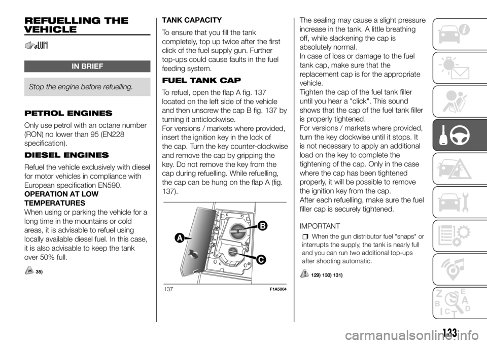
To refuel, open the flap A fig. 137
located on the left side of the vehicle
and then unscrew the cap B fig. 137 by
turning it anticlockwise.
For versions / markets where provided,
insert the ignition key in the lock of
the cap. Turn the key counter-clockwise
and remove the cap by gripping the
key. Do not remove the key from the
cap during refuelling. While refuelling,
the cap can be hung on the flap A (fig.
137).The sealing may cause a slight pressure
increase in the tank. A little breathing
off, while slackening the cap is
absolutely normal.
In case of loss or damage to the fuel
tank cap, make sure that the
replacement cap is for the appropriate
vehicle.
Tighten the cap of the fuel tank filler
until you hear a "click". This sound
shows that the cap of the fuel tank filler
is properly tightened.
For versions / markets where provided,
turn the key clockwise until it stops. It
is not necessary to apply an additional
load on the key to complete the
tightening of the cap. Only in the case
where the cap has been tightened
properly, it will be possible to remove
the ignition key from the cap.
After each refuelling, make sure the fuel
filler cap is securely tightened.
IMPORTANT
When the gun distributor fuel "snaps" or
interrupts the supply, the tank is nearly full
and you can run two additional top-ups
after shooting automatic.
129) 130) 131)
137F1A5004
133
Page 136 of 304
Topping for additive Diesel
Emissions AdBlue (UREA)
When refuelling the additive for Diesel
Emissions AdBlue (UREA) with
dispensing gun:
park the vehicle on ground level;
turn off the engine by turning the key
in the OFF position;
open the fuel flap A fig. 137 and
then unscrew and remove the cap C
fig. 137 from the UREA filler;
insert the dispensing gun for topping
up UREA in the filler neck;
immediately stop filling the tank
UREA if it shows one of the cases listed
below:
- if AdBlue is spilled out of the filler
neck, clean up well the area and
proceed to filling up again;
- if during filling the dispensing gun
clicks, it indicates that the UREA tank is
full. Do not proceed with the
replacement, to prevent spillage of
AdBlue (UREA).
When you have finished topping up,
refit the cap C fig. 137 on the UREA
filler by turning it clockwise until it is fully
tightened;
turn the key in the pawl starter in the
ON position (no need to start the
engine);
wait for the warning on the
instrument panel to switch off before
moving the vehicle, the warning light
may stay on for a few seconds to half a
minute. In case of motor start-up and
movement of the vehicle, the warning
light will remain on for a longer period of
time, but there are no problems on the
engine functionality. If topping up is
done with the UREA tank empty, you
have to wait two minutes before
starting the vehicle.
When refuelling the additive for
Diesel Emissions AdBlue (UREA)
with bottle:
park the vehicle on ground level;
turn off the engine by turning the key
in the OFF position;
open the fuel flap A fig. 137 and
then unscrew and remove the cap C
fig. 137 from the UREA filler;
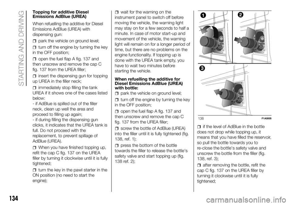
screw the bottle of AdBlue (UREA)
into the filler until it is fully tightened (fig.
138, ref. 1);
press the bottom of the bottle
towards the filler to release the bottle's
safety valve and start topping up (fig.
138 ref. 2);
if the level of AdBlue in the bottle
does not drop while topping up, it
means that you have filled the reservoir,
so pull the bottle towards you to
re-close the bottle's safety valve and
unscrew the bottle from the filler (fig.
138, ref. 3);
after removing the bottle, refit the
cap C fig. 137 on the UREA filler by
turning it clockwise until it is fully
tightened;
138F1A5005
134
STARTING AND DRIVING
Page 137 of 304
turn the key in the pawl starter in the
ON position (no need to start the
engine);
wait for the warning on the
instrument panel to switch off before
moving the vehicle, the warning light
may stay on for a few seconds to half a
minute. In case of motor start-up and
movement of the vehicle, the warning
light will remain on for a longer period of
time, but there are no problems on the
engine functionality;
if topping up is done with the UREA
tank empty, you have to wait two
minutes before starting the vehicle;
NOTE The driving conditions (altitude,
vehicle speed, load, etc.) determine the
quantity of UREA used by the vehicle.
In order to use the additive for Diesel
Emissions (UREA) correctly, see "Fluids
and lubricants" in the "Technical data".
132)
IMPORTANT
Exceeding the maximum filling level
of the tank UREA, it can cause damage
to the tank and spilling UREA. Please
avoid topping up after filling the tank.
DO NOT EXCEED THE MAXIMUM
LEVEL. The UREA freezes at under -11
° C. Although the system is designed
to operate below the freezing point
of the UREA, it is advisable not to fill the
tank beyond the maximum level
because if the UREA freezes the
system can be damaged.
If the UREA is spilled on painted
surfaces or aluminium, immediately
clean the area with water and use
absorbent material to collect the fluid
that has been spilled on the ground.
Do not try to start the engine if
UREA was accidentally added to the
Diesel fuel tank, this can result in
serious engine damage, contact
Dealership.
Use AdBlue only according to DIN
70 070 and ISO 22241-1. Other fluids
may cause damage to the system: also
exhaust emissions would no longer
comply with the law. The distribution
companies are responsible for the
compliance of their product. Observe
the precautions of storage and
servicing, in order to preserve the initial
qualities. The manufacturer of the
vehicle does not recognise any
guarantee in case of malfunctions and
damage caused to the vehicle due
to the use of urea (AdBlue) not in
accordance with regulations.
Any introduction of diesel fuel inside
the tank AdBlue, causes irreversible
damage to the pumping unit circuit
AdBlue.
Do not add additives to AdBlue. Do
not dilute AdBlue with tap water as
this may damage the system of
purification of exhaust gases.
In case of damage to the sewage
system of exhaust gas resulting from
the use of additives / tap water, the
introduction of diesel fuel, or at least by
not fulfilling the requirements, the
warranty expires.
AdBlue tank topping (UREA) in cold
environments
Since AdBlue (UREA) starts to freeze
around the -11 °C, the vehicle is
equipped with an automatic system of
heating UREA that allows the system to
function properly at temperatures
below -11 °C.
If the vehicle remains idle for a long
period at temperatures below the -11
°C, the UREA in the tank might freeze.
If the tank UREA was filled beyond
the maximum level and freezes, it can
be damaged; for this reason it is
advisable not to exceed the maximum
level of the tank.
Pay extra attention to avoid exceeding
the maximum level when you use
portable containers for topping up.
135
Page 141 of 304
The general recommendation is to
avoid emptying the petrol tank
completely, as this may lead to a
risk for the driver:
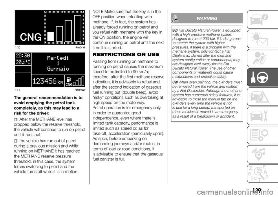
After the METHANE level has
dropped below the reserve threshold,
the vehicle will continue to run on petrol
until it runs out;
the vehicle has run out of petrol
during a previous mission and while
running on METHANE it has reached
the METHANE reserve pressure
threshold: in this case, the system
forces switching to petrol and the
vehicle turns off while it is in motion.NOTE Make sure that the key is in the
OFF position when refuelling with
methane. If, in fact, the system has
already forced running on petrol and
you refuel with methane with the key in
the ON position, the engine will
continue running on petrol until the next
time it is started.
RESTRICTIONS ON USE
Passing from running on methane to
running on petrol causes the maximum
speed to be limited to 90 km/h;
therefore, after the first methane reserve
indication, it is advisable to refuel and
after the second indication of gaseous
fuel running out (double beep), avoid
"risky" conditions such as overtaking at
high speed on the motorway.
Petrol operation is for emergency only.
In order to guarantee good
independence, even where there is
limited tank capacity, performance is
limited such as speed or, as for
take-off, acceleration (particularly uphill).
As such, before embarking on
demanding journeys and/or routes, in
terms of load or road conditions, it
is advisable to ensure that the gaseous
fuel canister is full.
WARNING
38)Fiat Ducato Natural Power is equipped
with a high pressure methane system
designed to run at 200 bar. It is dangerous
to stretch the system with higher
pressures. If there is a problem with the
methane system, only contact a Fiat
Dealership. Do not alter the methane
system configuration or components; they
are designed exclusively for the Fiat
Ducato Natural Power. The use of other
components or materials could cause
malfunctions and prejudice safety.
39)When oven painting, the cylinders must
be removed from the vehicle and refitted
by a Fiat Dealership. Although the methane
system has numerous safety features, it is
advisable to close the manual tap on the
cylinders every time the vehicle is not
in use for a long period, transported on
other vehicles or moved in an emergency
as a result of a breakdown or accident.
140F1A0436
141F0N0403I
139
Page 147 of 304

INSTRUCTIONS FOR
USING THE REMOVABLE
BALL HEAD TOW BAR
41) 42) 43) 44) 45) 46)
Before setting off, check the correct
locking of the removable ball head tow
bar, as follows:
The green mark of the flywheel must
coincide with the green mark on the
tow bar.
The flywheel is in the stop position
on the tow bar (without slot).
Locked lock and key removed. The
flywheel cannot be removed.
Ball head bar firmly secured to the
housing pipe. Check by shaking with a
hand.
The fitting procedure must be repeated
if any of the 4 checked requirements
is not met.
If even only one of the requirements is
not met the tow hook must not be
used, as in this case there is risk of
accidents. Contact the joint
manufacturer.
The ball head tow bar can be fitted and
removed manually, without needing
any tool.
Never use working tools or means, as
the mechanism could be damaged.
Never unlock in the case of trailer
attached to the vehicle or fitted rack.When driving without trailer or rack the
ball head tow bar must be removed
and the closing plug must always
be inserted in the housing pipe. This
applies particularly if the visibility of the
number plate characters or of the
lighting system is reduced.
Removable ball head tow bar fig.
144 - fig. 145 - fig. 146
1. Mounting pipe - 2. Ball head tow bar
- 3. Locking ball - 4. Release lever -
5. Handwheel - 6. Cap - 7. Wrench - 8.
Red mark (handwheel) - 9. Green
mark (handwheel) - 10. Green mark
(tow bar) - 11. Symbol (release control)
- 12. Closing plug - 13. Coupling pin
- 14. No gaps between 2 and5-15.
Gap of about 5 mm
Installing the ball head tow bar
1. Remove the plug from the mounting
pipe.
The ball head tow bar is usually in the
released position when taken out from
the boot. This can be observed by
the flywheel spaced from the tow bar,
corresponding to a slot of approx. 5
mm (see figure) and by the red mark on
the flywheel directed to the green
mark on the tow bar.
144F1A0380
145 - Locked position, drivingF1A0381
146 - Released position, removedF1A0382
145
Page 148 of 304
Please note that the tow bar can be
installed only when in these conditions.
If the locking mechanism of the tow
bar is disengaged before the
installation, or at any other time, and is
in the locked position, it must be
pre-loaded. The locked position can be
identified by the green mark of the
flywheel coinciding with the green mark
of the tow bar and by the flywheel in
the stop position on the tow bar,
namely without slot (see figure).
The locking mechanism is pre-loaded
as follows: with the key inserted and
the lock open, extract the flywheel
following the direction of the arrow and,
to pre-load, rotate according to the
direction of the arrow b until the stop.
The release lever is engaged and the
locking mechanism remains in the
pre-loading position even when the
flywheel is released. The tow bar must
be inserted in the housing pipe with the
coupling pin for the installation. Insert
from the bottom and push upwards.
The mechanism then locks
automatically. Keep your hands far from
the flywheel, as it rotates during the
locking procedure.2. The tow bar must be inserted in the
housing pipe with the coupling pin
for the installation. Insert from the
bottom and push upwards. The
mechanism then locks automatically.
Keep your hands far from the flywheel,
as it rotates during the locking
procedure.
3. Close the lock and always remove
the key. The key cannot be removed
when the lock is released. Apply the
protection cap on the lock.
Removing the tow bar
1. Remove the protection cap from the
lock and press it on the key grip. Open
the lock with the key.
2. Hold the tow bar firmly, remove the
flywheel following the direction of the
arrow and rotate according to the
direction of the arrow b until stopping,
so as to remove till the extracted
position. Then remove the tow bar from
the housing pipe. The flywheel can
then be released; it autonomously
stops in the released position.
3. Arrange the tow bar in the luggage
compartment so that it cannot be
dirtied or damaged by other
transported objects.
4. Insert the suitable plug in the
mounting pipe.
WARNING
41)The removable ball head bar must be
repaired and taken apart by the
manufacturer only.
42)The accompanying plate must be in a
highly visible point of the vehicle, near
the mounting pipe or inside the luggage
compartment.
43)To ensure correct operation of the
system, periodically remove all dirt deposits
from the ball head bar and from the
mounting pipe. The mechanical
components must be serviced at the
specified intervals. The lock must only be
treated with graphite.
44)Periodically lubricate the joints, the
sliding surfaces and the balls with grease
without resin or oil. Lubrication is also a
further corrosion protection.
45)If the vehicle is washed with high-
pressure jets, the ball head bar must be
removed and the dedicated cap fitted. The
ball head bar must never be treated with
steam jets.
46)Two keys are supplied together with
the removable ball tow bar. Note down the
key number on the pawl for any following
order and keep it.
146
STARTING AND DRIVING
Page 149 of 304
PROLONGED
VEHICLE INACTIVITY
If the vehicle needs to be off the road
for longer than one month, the following
precautions must be taken:
park the vehicle indoors in a dry
and, if possible, well-ventilated place;
engage a gear;
check that the handbrake is not
engaged;
disconnect the negative battery
terminal; if the vehicle is equipped with
a battery disconnection function
(disconnector), see the description of
the procedure in the "Controls"
paragraph in the "Dashboard and
controls" section;
clean and protect the painted parts
using protective wax;
clean and protect the shiny metal
parts using special compounds
available commercially;
sprinkle talcum powder on the
windscreen and rear window wiper
rubber blades and lift them off the
glass;
slightly open the windows;
cover the vehicle with a piece of
fabric or perforated plastic sheet. Do
not use compact plastic tarpaulins,
which prevent humidity from
evaporating from the surface of the
vehicle;
inflate tyres to +0.5 bar above the
standard specified pressure and check
it at intervals;
do not drain the engine cooling
system.
IMPORTANT If the vehicle is equipped
with an alarm system, switch off the
vehicle alarm with the remote control.
IMPORTANT After turning the ignition
key to STOP and having closed the
driver side door, wait at least one
minute before disconnecting the
electrical supply from the battery. When
reconnecting the electrical supply to
the battery, make sure that the ignition
key is in the STOP position and the
driver side door is closed.
147
Page 163 of 304
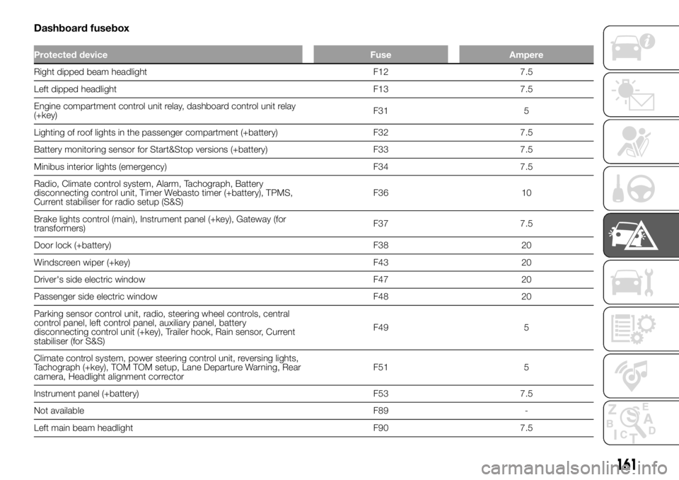
Dashboard fusebox
Protected device Fuse Ampere
Right dipped beam headlight F12 7.5
Left dipped headlight F13 7.5
Engine compartment control unit relay, dashboard control unit relay
(+key)F31 5
Lighting of roof lights in the passenger compartment (+battery) F32 7.5
Battery monitoring sensor for Start&Stop versions (+battery) F33 7.5
Minibus interior lights (emergency) F34 7.5
Radio, Climate control system, Alarm, Tachograph, Battery
disconnecting control unit, Timer Webasto timer (+battery), TPMS,
Current stabiliser for radio setup (S&S)F36 10
Brake lights control (main), Instrument panel (+key), Gateway (for
transformers)F37 7.5
Door lock (+battery) F38 20
Windscreen wiper (+key) F43 20
Driver's side electric window F47 20
Passenger side electric window F48 20
Parking sensor control unit, radio, steering wheel controls, central
control panel, left control panel, auxiliary panel, battery
disconnecting control unit (+key), Trailer hook, Rain sensor, Current
stabiliser (for S&S)F49 5
Climate control system, power steering control unit, reversing lights,
Tachograph (+key), TOM TOM setup, Lane Departure Warning, Rear
camera, Headlight alignment correctorF51 5
Instrument panel (+battery) F53 7.5
Not available F89 -
Left main beam headlight F90 7.5
161
Page 165 of 304
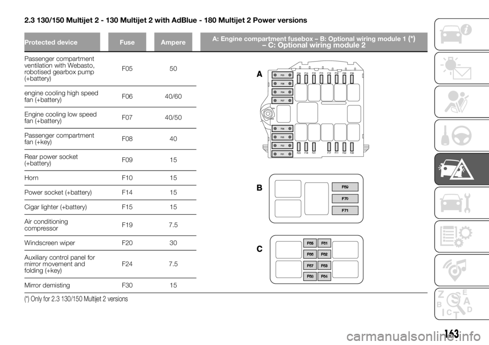
2.3 130/150 Multijet 2 - 130 Multijet 2 with AdBlue - 180 Multijet 2 Power versions
Protected device Fuse AmpereA: Engine compartment fusebox – B: Optional wiring module 1(*)
– C: Optional wiring module 2
Passenger compartment
ventilation with Webasto,
robotised gearbox pump
(+battery)F05 50
engine cooling high speed
fan (+battery)F06 40/60
Engine cooling low speed
fan (+battery)F07 40/50
Passenger compartment
fan (+key)F08 40
Rear power socket
(+battery)F09 15
Horn F10 15
Power socket (+battery) F14 15
Cigar lighter (+battery) F15 15
Air conditioning
compressorF19 7.5
Windscreen wiper F20 30
Auxiliary control panel for
mirror movement and
folding (+key)F24 7.5
Mirror demisting F30 15
(*) Only for 2.3 130/150 Multijet 2 versions
163
Page 167 of 304
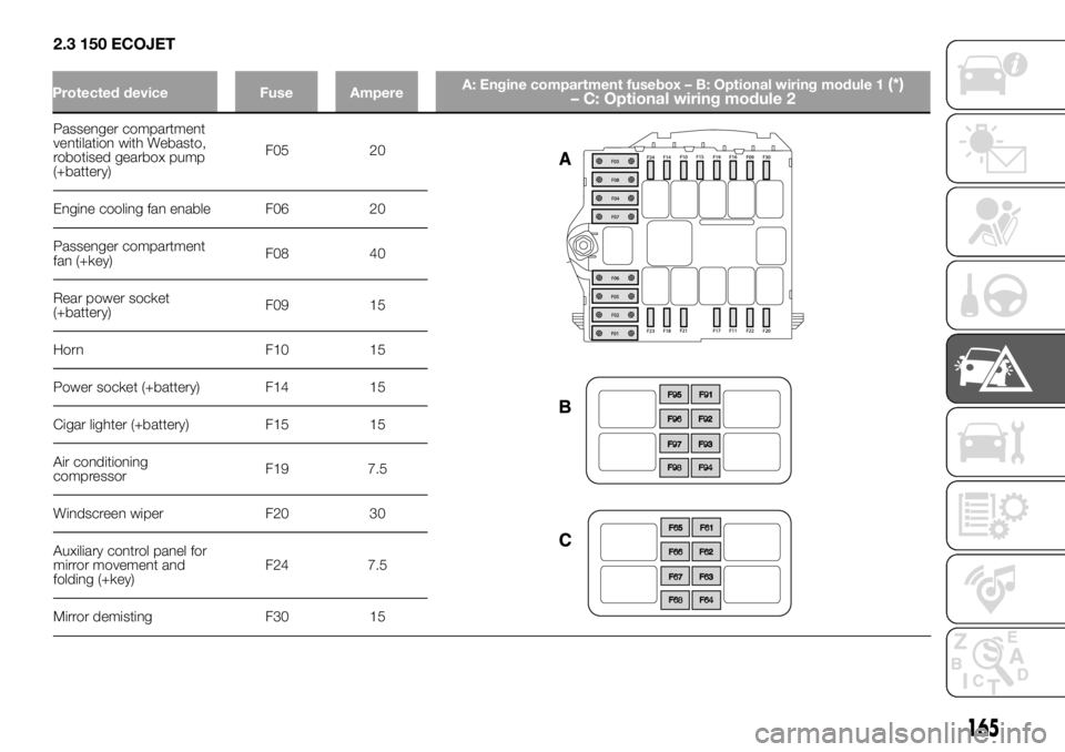
2.3 150 ECOJET
Passenger compartment
ventilation with Webasto,
robotised gearbox pump
(+battery)F05 20
Engine cooling fan enable F06 20
Passenger compartment
fan (+key)F08 40
Rear power socket
(+battery)F09 15
Horn F10 15
Power socket (+battery) F14 15
Cigar lighter (+battery) F15 15
Air conditioning
compressorF19 7.5
Windscreen wiper F20 30
Auxiliary control panel for
mirror movement and
folding (+key)F24 7.5
Mirror demisting F30 15
165
Protected device Fuse AmpereA: Engine compartment fusebox – B: Optional wiring module 1(*)
– C: Optional wiring module 2