relay FIAT DUCATO BASE CAMPER 2018 Owner handbook (in English)
[x] Cancel search | Manufacturer: FIAT, Model Year: 2018, Model line: DUCATO BASE CAMPER, Model: FIAT DUCATO BASE CAMPER 2018Pages: 304, PDF Size: 14.93 MB
Page 163 of 304

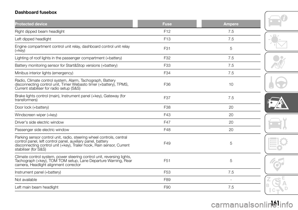
Dashboard fusebox
Protected device Fuse Ampere
Right dipped beam headlight F12 7.5
Left dipped headlight F13 7.5
Engine compartment control unit relay, dashboard control unit relay
(+key)F31 5
Lighting of roof lights in the passenger compartment (+battery) F32 7.5
Battery monitoring sensor for Start&Stop versions (+battery) F33 7.5
Minibus interior lights (emergency) F34 7.5
Radio, Climate control system, Alarm, Tachograph, Battery
disconnecting control unit, Timer Webasto timer (+battery), TPMS,
Current stabiliser for radio setup (S&S)F36 10
Brake lights control (main), Instrument panel (+key), Gateway (for
transformers)F37 7.5
Door lock (+battery) F38 20
Windscreen wiper (+key) F43 20
Driver's side electric window F47 20
Passenger side electric window F48 20
Parking sensor control unit, radio, steering wheel controls, central
control panel, left control panel, auxiliary panel, battery
disconnecting control unit (+key), Trailer hook, Rain sensor, Current
stabiliser (for S&S)F49 5
Climate control system, power steering control unit, reversing lights,
Tachograph (+key), TOM TOM setup, Lane Departure Warning, Rear
camera, Headlight alignment correctorF51 5
Instrument panel (+battery) F53 7.5
Not available F89 -
Left main beam headlight F90 7.5
161
Page 170 of 304

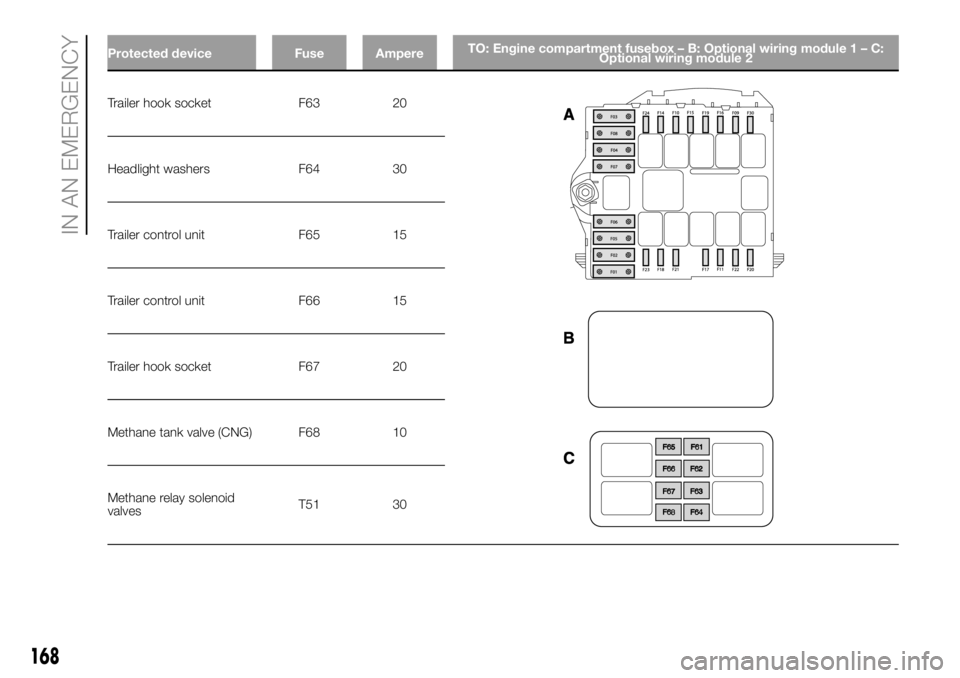
Protected device Fuse AmpereTO: Engine compartment fusebox – B: Optional wiring module1–C:
Optional wiring module 2
Trailer hook socket F63 20
Headlight washers F64 30
Trailer control unit F65 15
Trailer control unit F66 15
Trailer hook socket F67 20
Methane tank valve (CNG) F68 10
Methane relay solenoid
valvesT51 30
168
IN AN EMERGENCY
Page 187 of 304

VERSIONS WITH
START&STOP SYSTEM
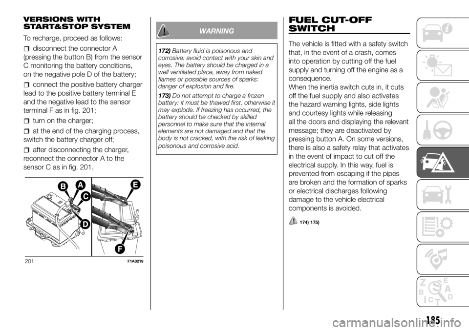
To recharge, proceed as follows:
disconnect the connector A
(pressing the button B) from the sensor
C monitoring the battery conditions,
on the negative pole D of the battery;
connect the positive battery charger
lead to the positive battery terminal E
and the negative lead to the sensor
terminal F as in fig. 201;
turn on the charger;
at the end of the charging process,
switch the battery charger off;
after disconnecting the charger,
reconnect the connector A to the
sensor C as in fig. 201.
WARNING
172)Battery fluid is poisonous and
corrosive: avoid contact with your skin and
eyes. The battery should be charged in a
well ventilated place, away from naked
flames or possible sources of sparks:
danger of explosion and fire.
173)Do not attempt to charge a frozen
battery: it must be thawed first, otherwise it
may explode. If freezing has occurred, the
battery should be checked by skilled
personnel to make sure that the internal
elements are not damaged and that the
body is not cracked, with the risk of leaking
poisonous and corrosive acid.
FUEL CUT-OFF
SWITCH
The vehicle is fitted with a safety switch
that, in the event of a crash, comes
into operation by cutting off the fuel
supply and turning off the engine as a
consequence.
When the inertia switch cuts in, it cuts
off the fuel supply and also activates
the hazard warning lights, side lights
and courtesy lights while releasing
all the doors and displaying the relevant
message; they are deactivated by
pressing button A. On some versions,
there is also a safety relay that activates
in the event of impact to cut off the
electrical supply. In this way, fuel is
prevented from escaping if the pipes
are broken and the formation of sparks
or electrical discharges following
damage to the vehicle electrical
components is avoided.
174) 175)
201F1A0219
185