boot FIAT FIORINO 2012 Owner handbook (in English)
[x] Cancel search | Manufacturer: FIAT, Model Year: 2012, Model line: FIORINO, Model: FIAT FIORINO 2012Pages: 210, PDF Size: 4.9 MB
Page 5 of 210
4
SAFETY
STARTING
AND DRIVING
WARNING
LIGHTS AND
MESSAGES
IN AN
EMERGENCY
MAINTENANCE
AND CARE
TECHNICAL
SPECIFICATIONS
INDEX
DASHBOARD
AND CONTROLSDASHBOARD........................................................................ 5
INSTRUMENT PANEL ......................................................... 6
SYMBOLS ............................................................................... 7
THE FIAT CODE SYSTEM ................................................. 7
THE KEYS .............................................................................. 8
ALARM ................................................................................... 11
IGNITION DEVICE ............................................................. 13
INSTRUMENTS .................................................................... 14
DIGITAL DISPLAY ............................................................... 16
MULTIFUNCTIONAL DISPLAY ...................................... 21
TRIP COMPUTER ................................................................ 30
SEATS ...................................................................................... 33
PARTITIONS .......................................................................... 36
HEAD RESTRAINTS............................................................. 38
STEERING WHEEL .............................................................. 39
REARVIEW MIRRORS......................................................... 39
HEATING AND CLIMATE CONTROL SYSTEM ........ 41
HEATING AND VENTILATION ...................................... 43
MANUAL CLIMATE CONTROL SYSTEM .................... 46
EXTERNAL LIGHTS ............................................................ 49WINDOW WASHING....................................................... 51
CEILING LIGHTS.................................................................. 52
CONTROLS ........................................................................... 55
INTERIOR FITTINGS........................................................... 56
DOORS .................................................................................. 59
WINDOW WINDERS ....................................................... 63
BOOT ...................................................................................... 64
BONNET................................................................................. 68
ROOF RACK/SKI RACK .................................................... 69
HEADLIGHTS........................................................................ 70
ABS SYSTEM ......................................................................... 71
ESP SYSTEM............................................................................ 72
TRACTION PLUS SYSTEM ............................................... 75
EOBD SYSTEM ..................................................................... 76
SPEED BLOCK ..................................................................... 76
PARKING SENSORS ........................................................... 77
SOUND SYSTEM.................................................................. 79
ELECTRICAL/ELECTRONIC DEVICES
INSTALLATION.................................................................... 80
VEHICLE REFUELLING........................................................ 80
ENVIRONMENTAL PROTECTION................................. 82
D D
A A
S S
H H
B B
O O
A A
R R
D D
A A
N N
D D
C C
O O
N N
T T
R R
O O
L L
S S
001-035 Fiorino GB 1ed:001-035 Fiorino GB 1ed 2-12-2009 16:13 Pagina 4
Page 12 of 210
11
SAFETY
STARTING
AND DRIVING
WARNING
LIGHTS AND
MESSAGES
IN AN
EMERGENCY
MAINTENANCE
AND CARE
TECHNICAL
SPECIFICATIONS
INDEX
DASHBOARD
AND CONTROLS
ALARM
(for versions/markets, where provided)
In addition to all the remote control func-
tions described above, an alarm has been
installed, which is controlled by a receiv-
er unit located under the dashboard near
the fuse box.
ALARM TRIPPING
The alarm trips in the following cases:
❒when one of the doors or bonnet is
opened illegitimately (perimeter pro-
tection);
❒when the ignition system is started up
(ignition key rotated to MAR);
❒when the battery cables are cut;
❒when someone is moving inside the
passenger compartment (volumetric
protection);
❒when the vehicle is unusually lift-
ed/tilted.
Depending on the markets where the ve-
hicle is sold, alarm tripping causes either
a siren or direction indicators to go on
(for approx. 26 seconds). Alarm tripping
and the number of cycles depend on the
sales market.Provision has been made for a maximum
number of acoustic/visual cycles, after
which the system resumes its standard
control function.
Volumetric and anti-lift protections are
disabled by pressing the control button in-
stalled on the front dashboard (see para-
graph “Anti-lift protections).
IMPORTANT The engine stop function is
guaranteed by the Fiat CODE, which is au-
tomatically activated when the ignition key
is extracted from the starter device.
ENABLING THE ALARM
Keep the doors and bonnets closed and
either turn the ignition key to STOPor
remove it. Direct the key with the remote
control towards the vehicle and press but-
ton
Á, then release it.
Excluding some versions for specific mar-
kets, the system produces a sound warn-
ing (beep) and enables door locking.
Before the alarm is enabled, a self-test is
run. If a failure is detected, the system pro-
duces a new acoustic signal and shows a
message on the display (see section
“Warning lights and messages”). If this is the case, disable the alarm by
pressing button Æ, check correct locking
of the doors, bonnet and boot, and enable
the alarm again by pressing button
Á.
If a door or the bonnet is not correctly
closed, it will be excluded from the test-
ing by the alarm system.
If the alarm produces an acoustic signal
even when the doors, bonnet and boot
are correctly closed, a failure has occurred
in system operation. Go to a Fiat Dealer-
ship.
IMPORTANT If the central door locking
system is engaged using the metal insert
of the key, the alarm is not enabled.
IMPORTANT Originally, the alarm is con-
figured in compliance with the regulations
existing in the different countries.
001-035 Fiorino GB 1ed:001-035 Fiorino GB 1ed 2-12-2009 16:14 Pagina 11
Page 65 of 210
64
SAFETY
STARTING
AND DRIVING
WARNING
LIGHTS AND
MESSAGES
IN AN
EMERGENCY
MAINTENANCE
AND CARE
TECHNICAL
SPECIFICATIONS
INDEX
DASHBOARD
AND CONTROLS
BOOT
EMERGENCY OPENING
FROM INSIDE
In case of emergency the boot can be
opened from inside the vehicle as de-
scribed below.
❒Open the side sliding door and lower
the backrest of the rear seat all the way
down so as to gain access to the load-
ing compartment (Combi versions).
or
❒Open the side sliding door (Cargo ver-
sions).
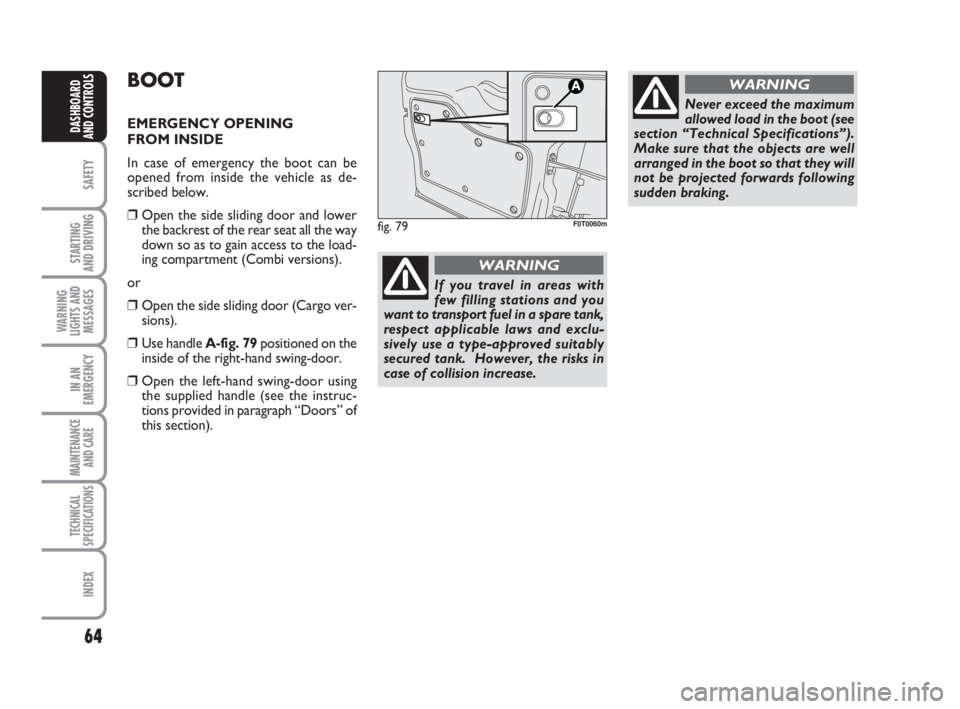
❒Use handle A-fig. 79positioned on the
inside of the right-hand swing-door.
❒Open the left-hand swing-door using
the supplied handle (see the instruc-
tions provided in paragraph “Doors” of
this section).
fig. 79F0T0060m
Never exceed the maximum
allowed load in the boot (see
section “Technical Specifications”).
Make sure that the objects are well
arranged in the boot so that they will
not be projected forwards following
sudden braking.
WARNING
If you travel in areas with
few filling stations and you
want to transport fuel in a spare tank,
respect applicable laws and exclu-
sively use a type-approved suitably
secured tank. However, the risks in
case of collision increase.
WARNING
036-082 Fiorino GB 1ed:036-082 Fiorino GB 1ed 30-11-2009 15:47 Pagina 64
Page 67 of 210
66
SAFETY
STARTING
AND DRIVING
WARNING
LIGHTS AND
MESSAGES
IN AN
EMERGENCY
MAINTENANCE
AND CARE
TECHNICAL
SPECIFICATIONS
INDEX
DASHBOARD
AND CONTROLS
EXPANDING THE BOOT
Proceed as follows:
❒open the rear doors and remove the
rear parcel shelf (see description in pre-
vious paragraph);
❒lower the rear seat head restraints all
the way down;❒move the seat belt sideways and check
that it is stretched and presents no
twisting;
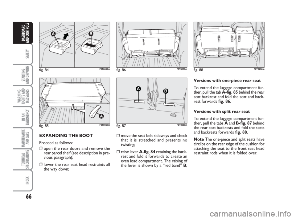
❒raise lever A-fig. 84retaining the back-
rest and fold it forwards to create an
even load compartment. The raising of
the lever is shown by a “red band” B;Versions with one-piece rear seat
To extend the luggage compartment fur-
ther, pull the tab A-fig. 85behind the rear
seat backrest and fold the seat and back-
rest forwards fig. 86.
Versions with split rear seat
To extend the luggage compartment fur-
ther, pull the tabs Aand B-fig. 87behind
the rear seat backrests and fold the seats
and backrests forwards fig. 88.
NoteThe one-piece and split seats have
circlips on the rear edge of the cushion for
attaching the seat to the front seat head
restraint rods when it is folded over.
fig. 84
AB
F0T0064m
fig. 85F0T0065m
fig. 86F0T0066m
fig. 87
AB
F0T0289m
fig. 88F0T0290m
036-082 Fiorino GB 1ed:036-082 Fiorino GB 1ed 30-11-2009 15:47 Pagina 66
Page 68 of 210
67
SAFETY
STARTING
AND DRIVING
WARNING
LIGHTS AND
MESSAGES
IN AN
EMERGENCY
MAINTENANCE
AND CARE
TECHNICAL
SPECIFICATIONS
INDEX
DASHBOARD
AND CONTROLS
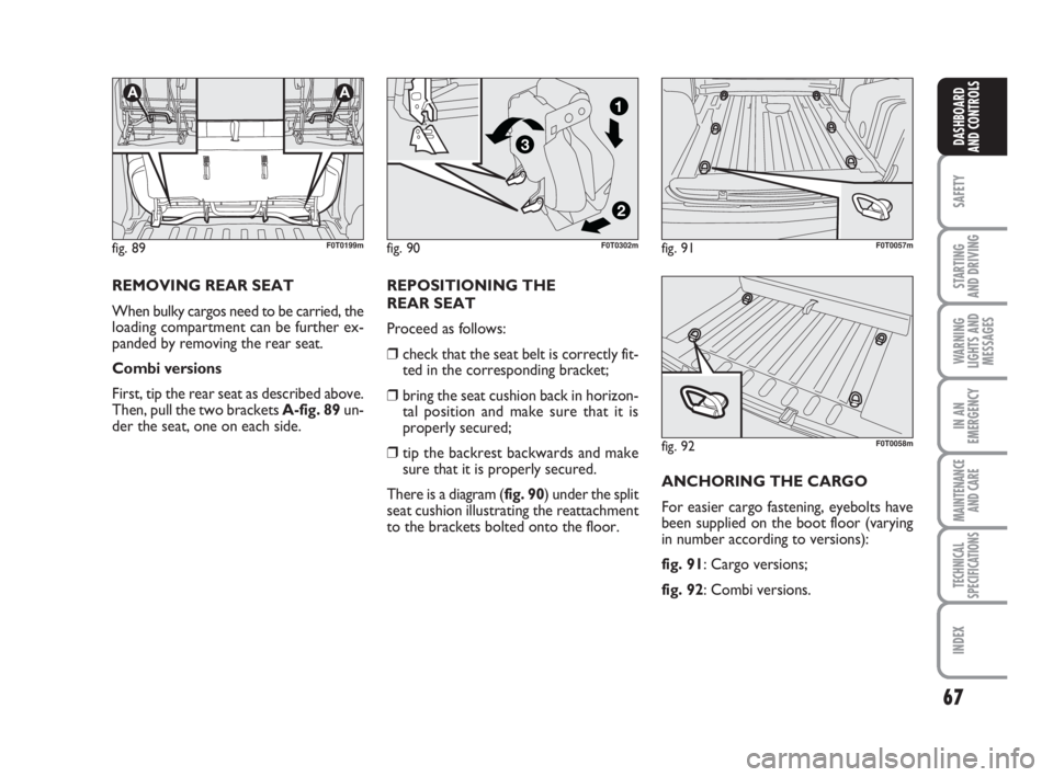
REMOVING REAR SEAT
When bulky cargos need to be carried, the
loading compartment can be further ex-
panded by removing the rear seat.
Combi versions
First, tip the rear seat as described above.
Then, pull the two brackets A-fig. 89un-
der the seat, one on each side.REPOSITIONING THE
REAR SEAT
Proceed as follows:
❒check that the seat belt is correctly fit-
ted in the corresponding bracket;
❒bring the seat cushion back in horizon-
tal position and make sure that it is
properly secured;
❒tip the backrest backwards and make
sure that it is properly secured.
There is a diagram (fig. 90) under the split
seat cushion illustrating the reattachment
to the brackets bolted onto the floor.
fig. 89
AA
F0T0199mfig. 91F0T0057m
fig. 92F0T0058m
ANCHORING THE CARGO
For easier cargo fastening, eyebolts have
been supplied on the boot floor (varying
in number according to versions):
fig. 91: Cargo versions;
fig. 92: Combi versions.
fig. 90
2
3
1
F0T0302m
036-082 Fiorino GB 1ed:036-082 Fiorino GB 1ed 30-11-2009 15:47 Pagina 67
Page 70 of 210
69
SAFETY
STARTING
AND DRIVING
WARNING
LIGHTS AND
MESSAGES
IN AN
EMERGENCY
MAINTENANCE
AND CARE
TECHNICAL
SPECIFICATIONS
INDEX
DASHBOARD
AND CONTROLS
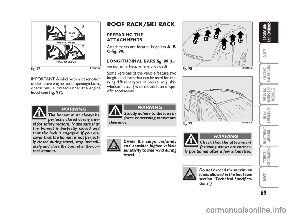
IMPORTANT A label with a description
of the above engine hood opening/closing
operations is located under the engine
hood (see fig. 97).
The bonnet must always be
perfectly closed during trav-
el for safety reasons. Make sure that
the bonnet is perfectly closed and
that the lock is engaged. If you dis-
cover that the bonnet is not perfect-
ly closed during travel, stop immedi-
ately and close the bonnet in the cor-
rect manner.
WARNING
fig. 97
F0Q0603m
12
CLACK
=
OK
PUSH TO OPEN12
PULL TO CLOSE
F0T0215mfig. 98F0T0154m
fig. 99F0T0176m
Strictly adhere to the laws in
force concerning maximum
clearance.
WARNING
Check that the attachment
fastening screws are correct-
ly positioned after a few kilometres.
WARNING
Divide the cargo uniformly
and consider higher vehicle
sensitivity to side wind during
travel.
Do not exceed the maximum
loads allowed in the boot (see
section “Technical Specifica-
tions”).
ROOF RACK/SKI RACK
PREPARING THE
ATTACHMENTS
Attachments are located in points A,B,
C-fig. 98.
LONGITUDINAL BARS fig. 99 (for
versions/markets, where provided)
Some versions of the vehicle feature two
longitudinal bars that can be used for car-
rying different types of objects (e.g. skis,
windsurf, etc…) with the addition of spe-
cific accessories.
036-082 Fiorino GB 1ed:036-082 Fiorino GB 1ed 30-11-2009 15:47 Pagina 69
Page 71 of 210
70
SAFETY
STARTING
AND DRIVING
WARNING
LIGHTS AND
MESSAGES
IN AN
EMERGENCY
MAINTENANCE
AND CARE
TECHNICAL
SPECIFICATIONS
INDEX
DASHBOARD
AND CONTROLS
HEADLIGHTS
DIRECTING THE BEAM
Correct direction of the headlights is es-
sential for the comfort and safety of the
driver and the other road users. To en-
sure the best visibility conditions during
travel with the headlights on the vehicle
must have beams aimed correctly. Con-
tact the Fiat Dealership to have the head-
lights checked and properly adjusted.
HEADLIGHT AIMING DEVICE
This device works with the key at MAR
and the dipped beam headlights on.
The vehicle slants backwards when it is
loaded, raising the beam. The beams must
therefore be directed again in this case.FOG LIGHT AIMING DEVICE
(for versions/markets, where provided)
Contact the Fiat Dealership to have the
fog lights checked and properly adjusted.
REGULATING THE BEAMS
ABROAD
Dipped beams factory adjustment depends
on the country where the vehicle is pur-
chased. In countries driving on the left, the
beams are aimed by affixing a purposeful-
ly studied adhesive film in order not to
dazzle the vehicles travelling in the oppo-
site direction. This adhesive film is pro-
vided in Lineaccessori Fiat and is available
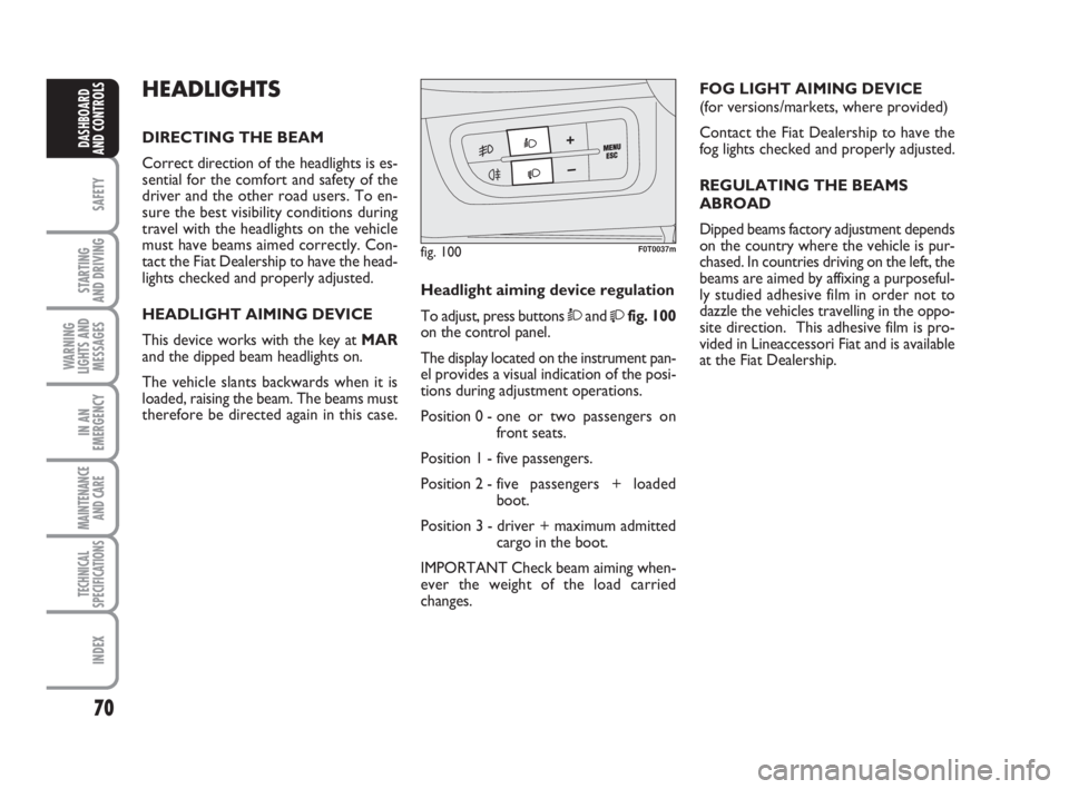
at the Fiat Dealership. Headlight aiming device regulation
To adjust, press buttons Òand
fig. 100
on the control panel.
The display located on the instrument pan-
el provides a visual indication of the posi-
tions during adjustment operations.
Position 0 - one or two passengers on
front seats.
Position 1 - five passengers.
Position 2 - five passengers + loaded
boot.
Position 3 - driver + maximum admitted
cargo in the boot.
IMPORTANT Check beam aiming when-
ever the weight of the load carried
changes.
fig. 100F0T0037m
036-082 Fiorino GB 1ed:036-082 Fiorino GB 1ed 30-11-2009 15:47 Pagina 70
Page 107 of 210
106
SAFETY
WARNING
LIGHTS AND
MESSAGES
IN AN
EMERGENCY
MAINTENANCE
AND CARE
TECHNICAL
SPECIFICATIONS
INDEX
DASHBOARDAND CONTROLS
STARTING
AND DRIVING
CONTAINING
RUNNING COSTS
Here are some useful tips to save fuel and
minimize polluting emissions of CO
2and
other pollutants (nitric oxide, unburnt hy-
drocarbons, fine dusts etc…).GENERAL REMARKS
Vehicle maintenance
Have checks and adjustments carried out
in accordance with the “Scheduled Service
Plan”.
Tyres
Check tyre pressure regularly at least
once every four weeks: excessively low
pressure will increase consumption be-
cause rolling resistance will be higher.
Unnecessary loads
Do not travel with an overloaded boot.
The weight of the vehicle (especially when
driving in town) and its trim greatly affect
fuel consumption and stability.
Roof rack/ski rack
Remove the roof rack or the ski rack from
the roof after use. These accessories de-
crease aerodynamic penetration of the ve-
hicle and have a negative effect on fuel
consumption. It is better to use a trailer
to transport particularly bulky objects.Electric devices
Use electric devices only for the amount
of time needed. The rear heated window,
additional headlights, windscreen wipers
and heater fan need a considerable
amount of energy, therefore increasing fu-
el consumption (up to +25% in the urban
cycle).
Climate control
The climate control system leads to high-
er fuel consumption (up to +20% on av-
erage): use air vents only when the ex-
ternal temperature allows it.
Spoilers
The use of non-certified spoilers may ad-
versely affect air drag and fuel consump-
tion levels.
101-110 Fiorino GB 1ed:101-110 Fiorino GB 1ed 30-11-2009 16:14 Pagina 106
Page 130 of 210
129
SAFETY
MAINTENANCE
AND CARE
TECHNICAL
SPECIFICATIONS
INDEX
DASHBOARDAND CONTROLS
STARTING
AND DRIVING
WARNING
LIGHTS AND
MESSAGES
IN AN
EMERGENCY
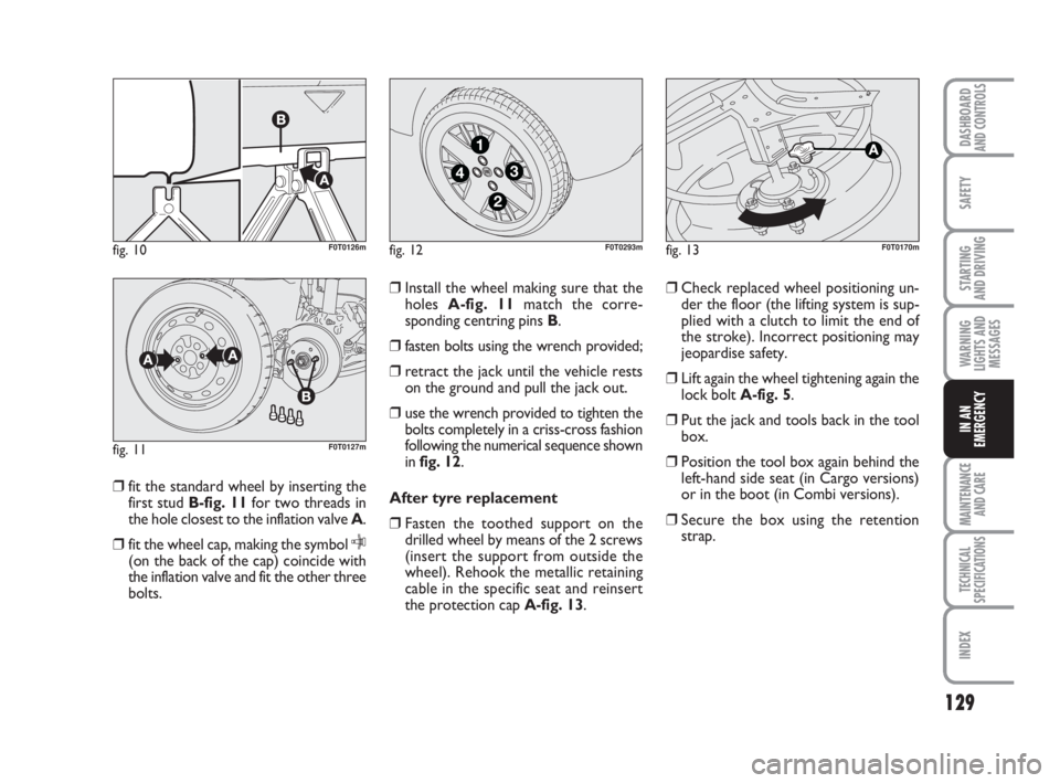
❒fit the standard wheel by inserting the
first stud B-fig. 11for two threads in
the hole closest to the inflation valve A.
❒fit the wheel cap, making the symbol
C(on the back of the cap) coincide with
the inflation valve and fit the other three
bolts.❒Install the wheel making sure that the
holes A-fig. 11match the corre-
sponding centring pins B.
❒fasten bolts using the wrench provided;
❒retract the jack until the vehicle rests
on the ground and pull the jack out.
❒use the wrench provided to tighten the
bolts completely in a criss-cross fashion
following the numerical sequence shown
in fig. 12.
After tyre replacement
❒Fasten the toothed support on the
drilled wheel by means of the 2 screws
(insert the support from outside the
wheel). Rehook the metallic retaining
cable in the specific seat and reinsert
the protection cap A-fig. 13.❒Check replaced wheel positioning un-
der the floor (the lifting system is sup-
plied with a clutch to limit the end of
the stroke). Incorrect positioning may
jeopardise safety.
❒Lift again the wheel tightening again the
lock boltA-fig. 5.
❒Put the jack and tools back in the tool
box.
❒Position the tool box again behind the
left-hand side seat (in Cargo versions)
or in the boot (in Combi versions).
❒Secure the box using the retention
strap.
fig. 10F0T0126m
fig. 11F0T0127m
fig. 12
4
1
3
2
F0T0293mfig. 13F0T0170m
123-154 Fiorino GB 1ed:123-154 Fiorino GB 1ed 3-12-2009 15:33 Pagina 129
Page 131 of 210
130
SAFETY
MAINTENANCE
AND CARE
TECHNICAL
SPECIFICATIONS
INDEX
DASHBOARDAND CONTROLS
STARTING
AND DRIVING
WARNING
LIGHTS AND
MESSAGES
IN AN
EMERGENCY
QUICK TYRE REPAIR
KIT FIX & GO automatic
The automatic fast tyre repair kit Fix & Go
automatic is placed in a container in the
boot.
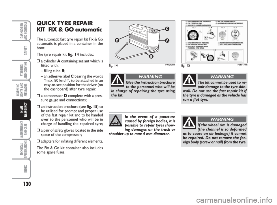
The tyre repair kit fig. 14includes:
❒a cylinder A containing sealant which is
fitted with:
– filling tube B;
– an adhesive label Cbearing the words
“max. 80 km/h”, to be attached in an
easy-to-see position for the driver (on
the dashboard) after tyre repair;
❒a compressor Dcomplete with a pres-
sure gauge and connections;
❒an instruction brochure (see fig. 15) to
be utilised for prompt and proper use
of the fast repair kit and to be handed
over to the personnel who will be in
charge of handling the repaired tyre;
❒a pair of safety gloves located in the side
space of the compressor;
❒adapters for inflating different elements.
The Fix & Go kit container also includes
some spare fuses.
fig. 14F0T0129mfig. 15F0T0130m
Give the instruction brochure
to the personnel who will be
in charge of repairing the tyre using
the kit.
WARNING
The kit cannot be used to re-
pair damage to the tyre side-
wall. Do not use the fast repair kit if
the tyre is damaged as the vehicle has
run a flat tyre.
WARNING
If the wheel rim is damaged
(the channel is so deformed
as to cause an air leakage) it cannot
be repaired. Do not remove the for-
eign body (screw or nail) from the tyre.
WARNINGIn the event of a puncture
caused by foreign bodies, it is
possible to repair tyres show-
ing damages on the track or
shoulder up to max 4 mm diameter.
123-154 Fiorino GB 1ed:123-154 Fiorino GB 1ed 3-12-2009 15:33 Pagina 130