dashboard FIAT FIORINO 2013 Owner handbook (in English)
[x] Cancel search | Manufacturer: FIAT, Model Year: 2013, Model line: FIORINO, Model: FIAT FIORINO 2013Pages: 210, PDF Size: 4.9 MB
Page 35 of 210
34
SAFETY
STARTING
AND DRIVING
WARNING
LIGHTS AND
MESSAGES
IN AN
EMERGENCY
MAINTENANCE
AND CARE
TECHNICAL
SPECIFICATIONS
INDEX
DASHBOARD
AND CONTROLS
RECESSING FOLDABLE
PASSENGER’S SEAT
(for versions/markets, where provided)
Some versions have the passenger’s seat
which folds into a recessed compartment.
IMPORTANT Only move the seat if there
are no passengers in the rear seats.
Folding the seat
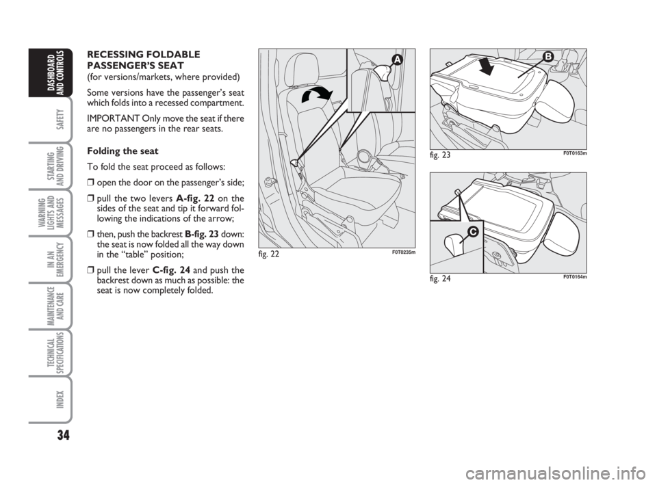
To fold the seat proceed as follows:
❒open the door on the passenger’s side;
❒pull the two levers A-fig. 22on the
sides of the seat and tip it forward fol-
lowing the indications of the arrow;
❒then, push the backrest B-fig. 23down:
the seat is now folded all the way down
in the “table” position;
❒pull the lever C-fig. 24and push the
backrest down as much as possible: the
seat is now completely folded.
fig. 22F0T0235m
fig. 23F0T0163m
fig. 24F0T0164m
001-035 Fiorino GB 1ed:001-035 Fiorino GB 1ed 2-12-2009 16:14 Pagina 34
Page 36 of 210
35
SAFETY
STARTING
AND DRIVING
WARNING
LIGHTS AND
MESSAGES
IN AN
EMERGENCY
MAINTENANCE
AND CARE
TECHNICAL
SPECIFICATIONS
INDEX
DASHBOARD
AND CONTROLS
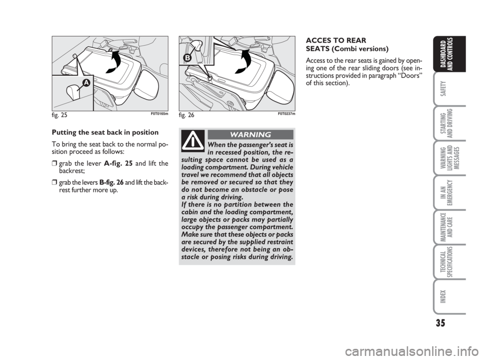
fig. 25F0T0165mfig. 26F0T0237m
Putting the seat back in position
To bring the seat back to the normal po-
sition proceed as follows:
❒grab the lever A-fig. 25and lift the
backrest;
❒grab the levers B-fig. 26and lift the back-
rest further more up.
When the passenger’s seat is
in recessed position, the re-
sulting space cannot be used as a
loading compartment. During vehicle
travel we recommend that all objects
be removed or secured so that they
do not become an obstacle or pose
a risk during driving.
If there is no partition between the
cabin and the loading compartment,
large objects or packs may partially
occupy the passenger compartment.
Make sure that these objects or packs
are secured by the supplied restraint
devices, therefore not being an ob-
stacle or posing risks during driving.
WARNING
ACCES TO REAR
SEATS (Combi versions)
Access to the rear seats is gained by open-
ing one of the rear sliding doors (see in-
structions provided in paragraph “Doors”
of this section).
001-035 Fiorino GB 1ed:001-035 Fiorino GB 1ed 2-12-2009 16:14 Pagina 35
Page 37 of 210
36
SAFETY
STARTING
AND DRIVING
WARNING
LIGHTS AND
MESSAGES
IN AN
EMERGENCY
MAINTENANCE
AND CARE
TECHNICAL
SPECIFICATIONS
INDEX
DASHBOARD
AND CONTROLS
PARTITIONS
(for versions/markets, where provided)
CARGO VERSIONS
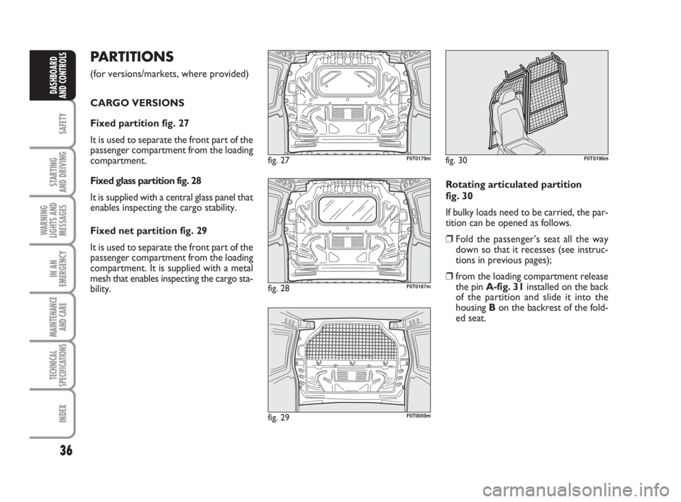
Fixed partition fig. 27
It is used to separate the front part of the
passenger compartment from the loading
compartment.
Fixed glass partition fig. 28
It is supplied with a central glass panel that
enables inspecting the cargo stability.
Fixed net partition fig. 29
It is used to separate the front part of the
passenger compartment from the loading
compartment. It is supplied with a metal
mesh that enables inspecting the cargo sta-
bility.
fig. 27F0T0179m
Rotating articulated partition
fig. 30
If bulky loads need to be carried, the par-
tition can be opened as follows.
❒Fold the passenger’s seat all the way
down so that it recesses (see instruc-
tions in previous pages);
❒from the loading compartment release
the pin A-fig. 31installed on the back
of the partition and slide it into the
housing B on the backrest of the fold-
ed seat.
fig. 28F0T0167m
fig. 30F0T0196m
fig. 29F0T0059m
036-082 Fiorino GB 1ed:036-082 Fiorino GB 1ed 30-11-2009 15:46 Pagina 36
Page 38 of 210
37
SAFETY
STARTING
AND DRIVING
WARNING
LIGHTS AND
MESSAGES
IN AN
EMERGENCY
MAINTENANCE
AND CARE
TECHNICAL
SPECIFICATIONS
INDEX
DASHBOARD
AND CONTROLS
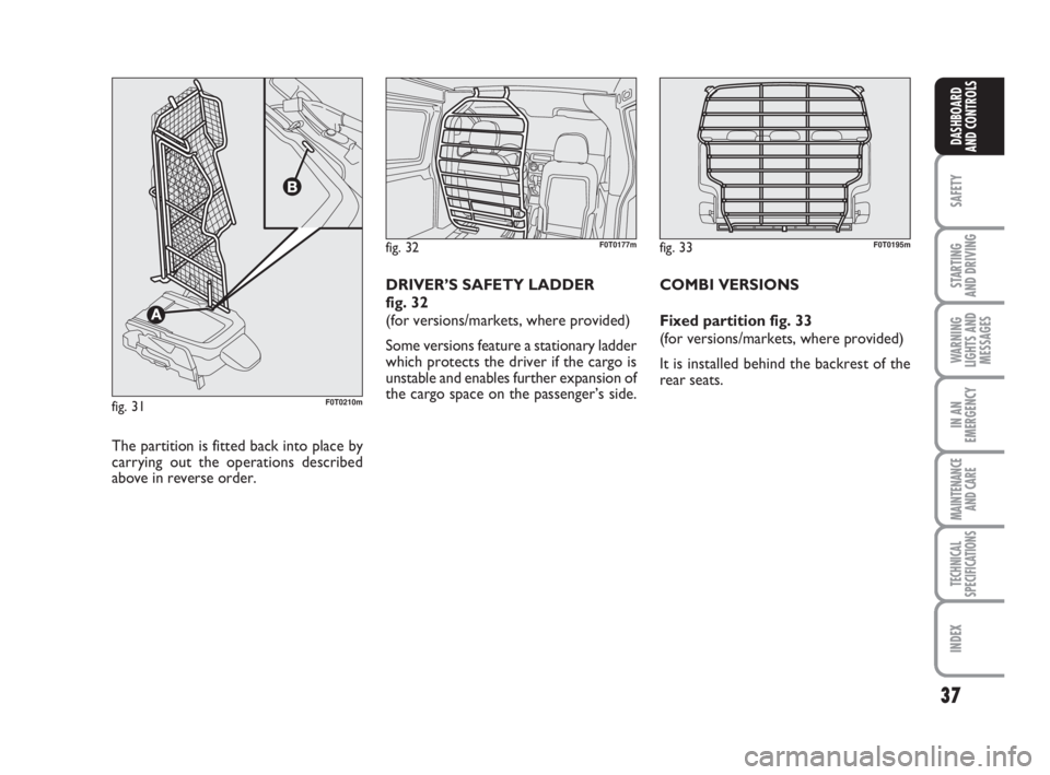
fig. 32F0T0177m
The partition is fitted back into place by
carrying out the operations described
above in reverse order.DRIVER’S SAFETY LADDER
fig. 32
(for versions/markets, where provided)
Some versions feature a stationary ladder
which protects the driver if the cargo is
unstable and enables further expansion of
the cargo space on the passenger’s side.
fig. 31F0T0210m
fig. 33F0T0195m
COMBI VERSIONS
Fixed partition fig. 33
(for versions/markets, where provided)
It is installed behind the backrest of the
rear seats.
036-082 Fiorino GB 1ed:036-082 Fiorino GB 1ed 30-11-2009 15:46 Pagina 37
Page 39 of 210
38
SAFETY
STARTING
AND DRIVING
WARNING
LIGHTS AND
MESSAGES
IN AN
EMERGENCY
MAINTENANCE
AND CARE
TECHNICAL
SPECIFICATIONS
INDEX
DASHBOARD
AND CONTROLS
HEAD RESTRAINTS
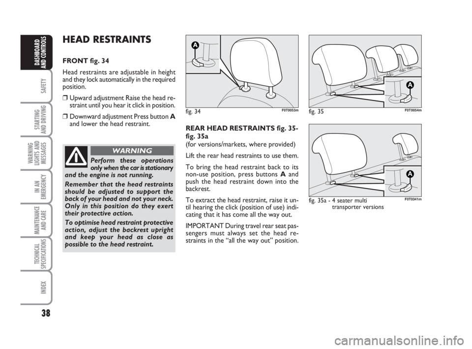
FRONT fig. 34
Head restraints are adjustable in height
and they lock automatically in the required
position.
❒Upward adjustment Raise the head re-
straint until you hear it click in position.
❒Downward adjustment Press button A
and lower the head restraint.
fig. 34F0T0053m
Perform these operations
only when the car is stationary
and the engine is not running.
Remember that the head restraints
should be adjusted to support the
back of your head and not your neck.
Only in this position do they exert
their protective action.
To optimise head restraint protective
action, adjust the backrest upright
and keep your head as close as
possible to the head restraint.
WARNING
REAR HEAD RESTRAINTS fig. 35-
fig. 35a
(for versions/markets, where provided)
Lift the rear head restraints to use them.
To bring the head restraint back to its
non-use position, press buttons Aand
push the head restraint down into the
backrest.
To extract the head restraint, raise it un-
til hearing the click (position of use) indi-
cating that it has come all the way out.
IMPORTANT During travel rear seat pas-
sengers must always set the head re-
straints in the “all the way out” position.
fig. 35F0T0054m
fig. 35a - 4 seater multi
transporter versions
A
F0T0341m
036-082 Fiorino GB 1ed:036-082 Fiorino GB 1ed 30-11-2009 15:46 Pagina 38
Page 40 of 210
39
SAFETY
STARTING
AND DRIVING
WARNING
LIGHTS AND
MESSAGES
IN AN
EMERGENCY
MAINTENANCE
AND CARE
TECHNICAL
SPECIFICATIONS
INDEX
DASHBOARD
AND CONTROLS
Perform these adjustments
only when the vehicle is sta-
tionary and the engine is not running.
WARNING
Under no circumstances
should aftermarket opera-
tions involving steering system or
steering column modifications (e.g.:
installation of anti-theft device) be
carried out that could badly affect
performance and safety. This also
causes the warranty to become null
and void and results in vehicle non-
compliance with type-approval re-
quirements.
WARNING
fig. 36F0T0040m
STEERING WHEEL
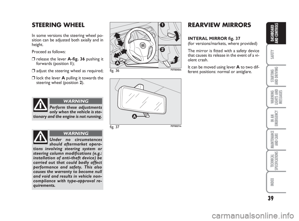
In some versions the steering wheel po-
sition can be adjusted both axially and in
height.
Proceed as follows:
❒release the lever A-fig. 36pushing it
forwards (position 1);
❒adjust the steering wheel as required;
❒lock the lever Apulling it towards the
steering wheel (position2).
REARVIEW MIRRORS
INTERAL MIRROR fig. 37
(for versions/markets, where provided)
The mirror is fitted with a safety device
that causes its release in the event of a vi-
olent crash.
It can be moved using lever Ato two dif-
ferent positions: normal or antiglare.
fig. 37F0T0027m
036-082 Fiorino GB 1ed:036-082 Fiorino GB 1ed 30-11-2009 15:46 Pagina 39
Page 41 of 210
40
SAFETY
STARTING
AND DRIVING
WARNING
LIGHTS AND
MESSAGES
IN AN
EMERGENCY
MAINTENANCE
AND CARE
TECHNICAL
SPECIFICATIONS
INDEX
DASHBOARD
AND CONTROLS
fig. 38F0T0042m
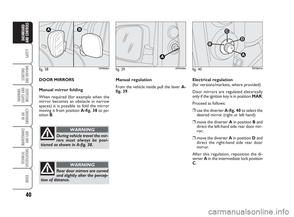
During vehicle travel the mir-
rors must always be posi-
tioned as shown in A-fig. 38.
WARNING
fig. 39F0T0194mfig. 40
B
C
D
F0T0041m
Manual regulation
From the vehicle inside pull the lever A-
fig. 39. DOOR MIRRORS
Manual mirror folding
When required (for example when the
mirror becomes an obstacle in narrow
spaces) it is possible to fold the mirror
moving it from position A-fig. 38to po-
sition B.Electrical regulation
(for versions/markets, where provided)
Door mirrors are regulated electrically
only if the ignition key is in position MAR.
Proceed as follows:
❒use the diverter A-fig. 40to select the
desired mirror (right or left hand):
❒move the diverter Ain position Band
direct the left-hand side rear door mir-
ror;
❒move the diverter Ain position Dand
direct the right-hand side rear door
mirror.
After this regulation, reposition the di-
verter Ain the intermediate lock position
C.
Rear door mirrors are curved
and slightly alter the percep-
tion of distance.
WARNING
036-082 Fiorino GB 1ed:036-082 Fiorino GB 1ed 30-11-2009 15:46 Pagina 40
Page 42 of 210
41
SAFETY
STARTING
AND DRIVING
WARNING
LIGHTS AND
MESSAGES
IN AN
EMERGENCY
MAINTENANCE
AND CARE
TECHNICAL
SPECIFICATIONS
INDEX
DASHBOARD
AND CONTROLS
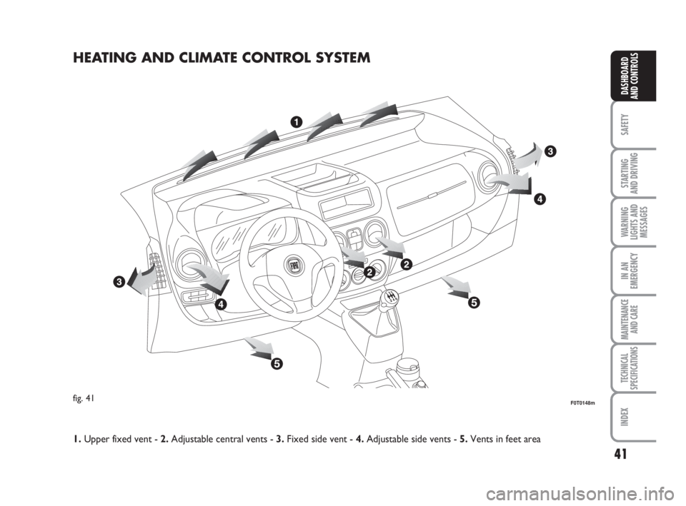
HEATING AND CLIMATE CONTROL SYSTEM
fig. 41F0T0148m
1.Upper fixed vent - 2.Adjustable central vents - 3.Fixed side vent - 4.Adjustable side vents - 5.Vents in feet area
036-082 Fiorino GB 1ed:036-082 Fiorino GB 1ed 30-11-2009 15:47 Pagina 41
Page 43 of 210
42
SAFETY
STARTING
AND DRIVING
WARNING
LIGHTS AND
MESSAGES
IN AN
EMERGENCY
MAINTENANCE
AND CARE
TECHNICAL
SPECIFICATIONS
INDEX
DASHBOARD
AND CONTROLS
fig. 43F0T0030mfig. 42F0T0031m
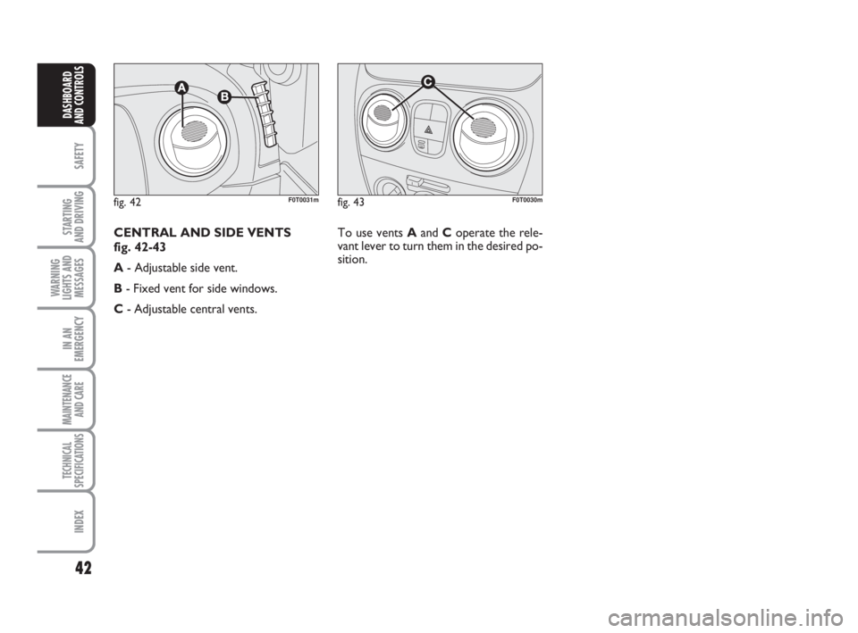
To use vents Aand Coperate the rele-
vant lever to turn them in the desired po-
sition. CENTRAL AND SIDE VENTS
fig. 42-43
A- Adjustable side vent.
B- Fixed vent for side windows.
C- Adjustable central vents.
036-082 Fiorino GB 1ed:036-082 Fiorino GB 1ed 30-11-2009 15:47 Pagina 42
Page 44 of 210
43
SAFETY
STARTING
AND DRIVING
WARNING
LIGHTS AND
MESSAGES
IN AN
EMERGENCY
MAINTENANCE
AND CARE
TECHNICAL
SPECIFICATIONS
INDEX
DASHBOARD
AND CONTROLS
HEATING AND VENTILATION
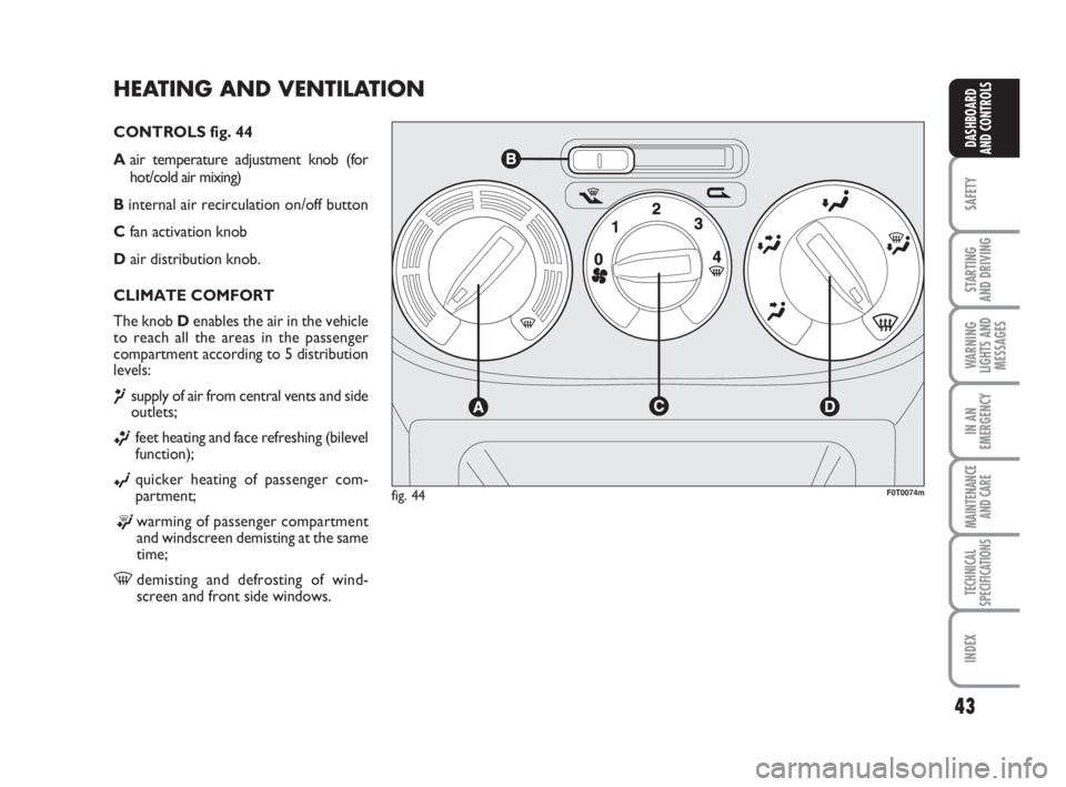
CONTROLS fig. 44
Aair temperature adjustment knob (for
hot/cold air mixing)
Binternal air recirculation on/off button
Cfan activation knob
Dair distribution knob.
CLIMATE COMFORT
The knob Denables the air in the vehicle
to reach all the areas in the passenger
compartment according to 5 distribution
levels:
¶supply of air from central vents and side
outlets;
ßfeet heating and face refreshing (bilevel
function);
©quicker heating of passenger com-
partment;
®warming of passenger compartment
and windscreen demisting at the same
time;
-demisting and defrosting of wind-
screen and front side windows.
fig. 44F0T0074m
036-082 Fiorino GB 1ed:036-082 Fiorino GB 1ed 30-11-2009 15:47 Pagina 43