clock FIAT FIORINO 2014 Owner handbook (in English)
[x] Cancel search | Manufacturer: FIAT, Model Year: 2014, Model line: FIORINO, Model: FIAT FIORINO 2014Pages: 210, PDF Size: 4.9 MB
Page 136 of 210
135
SAFETY
MAINTENANCE
AND CARE
TECHNICAL
SPECIFICATIONS
INDEX
DASHBOARDAND CONTROLS
STARTING
AND DRIVING
WARNING
LIGHTS AND
MESSAGES
IN AN
EMERGENCY
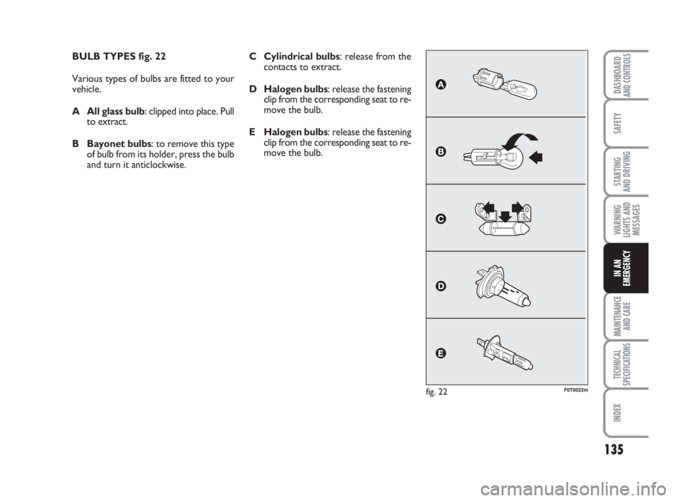
BULB TYPES fig. 22
Various types of bulbs are fitted to your
vehicle.
A All glass bulb: clipped into place. Pull
to extract.
B Bayonet bulbs: to remove this type
of bulb from its holder, press the bulb
and turn it anticlockwise.
fig. 22F0T0022m
C Cylindrical bulbs: release from the
contacts to extract.
D Halogen bulbs: release the fastening
clip from the corresponding seat to re-
move the bulb.
E Halogen bulbs: release the fastening
clip from the corresponding seat to re-
move the bulb.
123-154 Fiorino GB 1ed:123-154 Fiorino GB 1ed 3-12-2009 15:33 Pagina 135
Page 138 of 210
137
SAFETY
MAINTENANCE
AND CARE
TECHNICAL
SPECIFICATIONS
INDEX
DASHBOARDAND CONTROLS
STARTING
AND DRIVING
WARNING
LIGHTS AND
MESSAGES
IN AN
EMERGENCY
IF AN EXTERIOR
LIGHT BURNS OUT
For the type of bulb and power rating, see
“When needing to change a bulb”.
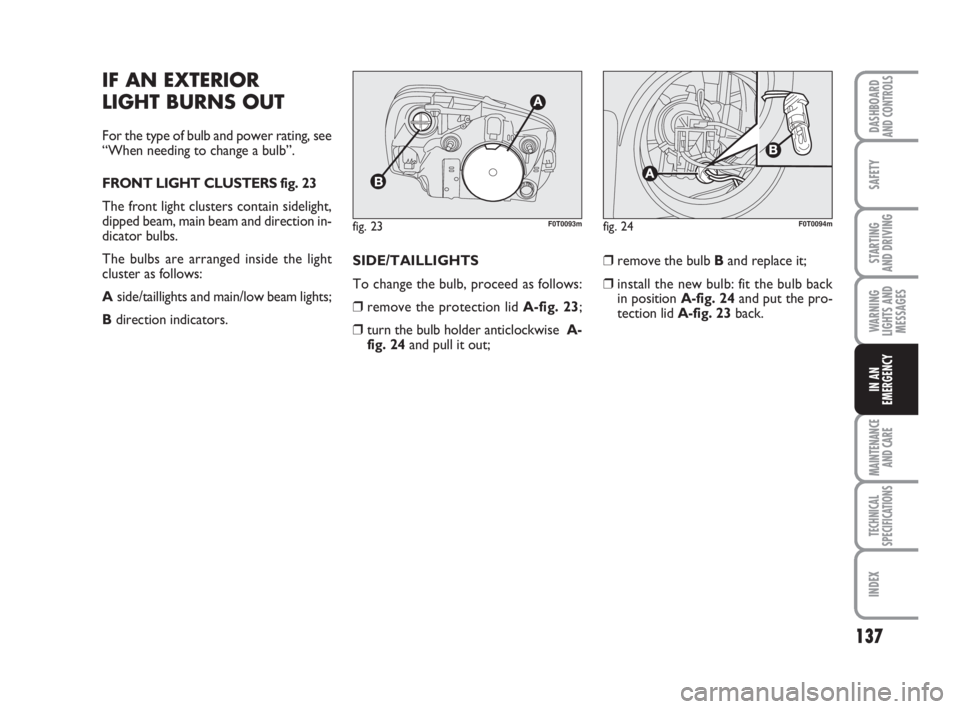
FRONT LIGHT CLUSTERS fig. 23
The front light clusters contain sidelight,
dipped beam, main beam and direction in-
dicator bulbs.
The bulbs are arranged inside the light
cluster as follows:
Aside/taillights and main/low beam lights;
Bdirection indicators.SIDE/TAILLIGHTS
To change the bulb, proceed as follows:
❒remove the protection lid A-fig. 23;
❒turn the bulb holder anticlockwise A-
fig. 24and pull it out;❒remove the bulb Band replace it;
❒install the new bulb: fit the bulb back
in position A-fig. 24and put the pro-
tection lid A-fig. 23back.
fig. 23F0T0093mfig. 24F0T0094m
123-154 Fiorino GB 1ed:123-154 Fiorino GB 1ed 3-12-2009 15:33 Pagina 137
Page 139 of 210
138
SAFETY
MAINTENANCE
AND CARE
TECHNICAL
SPECIFICATIONS
INDEX
DASHBOARDAND CONTROLS
STARTING
AND DRIVING
WARNING
LIGHTS AND
MESSAGES
IN AN
EMERGENCY
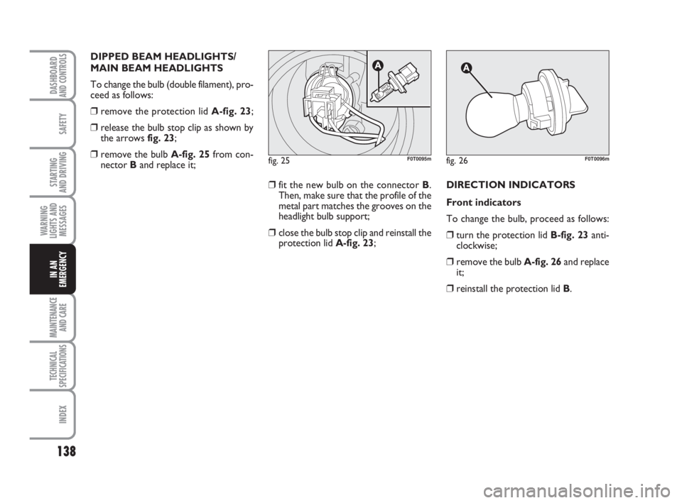
DIPPED BEAM HEADLIGHTS/
MAIN BEAM HEADLIGHTS
To change the bulb (double filament), pro-
ceed as follows:
❒remove the protection lid A-fig. 23;
❒release the bulb stop clip as shown by
the arrows fig. 23;
❒remove the bulb A-fig. 25from con-
nector Band replace it;
❒fit the new bulb on the connector B.
Then, make sure that the profile of the
metal part matches the grooves on the
headlight bulb support;
❒close the bulb stop clip and reinstall the
protection lid A-fig. 23;DIRECTION INDICATORS
Front indicators
To change the bulb, proceed as follows:
❒turn the protection lid B-fig. 23anti-
clockwise;
❒remove the bulb A-fig. 26and replace
it;
❒reinstall the protection lid B.
fig. 25F0T0095mfig. 26F0T0096m
123-154 Fiorino GB 1ed:123-154 Fiorino GB 1ed 3-12-2009 15:33 Pagina 138
Page 140 of 210
139
SAFETY
MAINTENANCE
AND CARE
TECHNICAL
SPECIFICATIONS
INDEX
DASHBOARDAND CONTROLS
STARTING
AND DRIVING
WARNING
LIGHTS AND
MESSAGES
IN AN
EMERGENCY
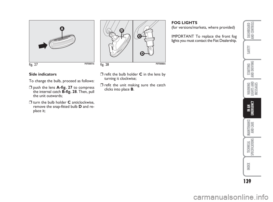
Side indicators
To change the bulb, proceed as follows:
❒push the lens A-fig. 27to compress
the internal catch B-fig. 28. Then, pull
the unit outwards;
❒turn the bulb holder C anticlockwise,
remove the snap-fitted bulb Dand re-
place it;
fig. 27F0T0097mfig. 28F0T0098m
❒refit the bulb holder Cin the lens by
turning it clockwise;
❒refit the unit making sure the catch
clicks into place B.FOG LIGHTS
(for versions/markets, where provided)
IMPORTANT To replace the front fog
lights you must contact the Fiat Dealership.
123-154 Fiorino GB 1ed:123-154 Fiorino GB 1ed 3-12-2009 15:33 Pagina 139
Page 142 of 210

141
SAFETY
MAINTENANCE
AND CARE
TECHNICAL
SPECIFICATIONS
INDEX
DASHBOARDAND CONTROLS
STARTING
AND DRIVING
WARNING
LIGHTS AND
MESSAGES
IN AN
EMERGENCY
3rdSTOP LIGHTS fig. 33
To replace the 3
rdstop lights you must
contact the Fiat Dealership.
fig. 33F0T0103mfig. 34F0T0104mfig. 35F0T0105m
PLATE LIGHTS
To replace the bulbs A-fig. 34proceed as
follows:
❒pull the tongues indicated by the arrows
and remove the bulb holders;
❒turn the bulb holder B-fig. 35clock-
wise and take the bulb Cout.
123-154 Fiorino GB 1ed:123-154 Fiorino GB 1ed 3-12-2009 15:33 Pagina 141
Page 147 of 210
146
SAFETY
MAINTENANCE
AND CARE
TECHNICAL
SPECIFICATIONS
INDEX
DASHBOARDAND CONTROLS
STARTING
AND DRIVING
WARNING
LIGHTS AND
MESSAGES
IN AN
EMERGENCY
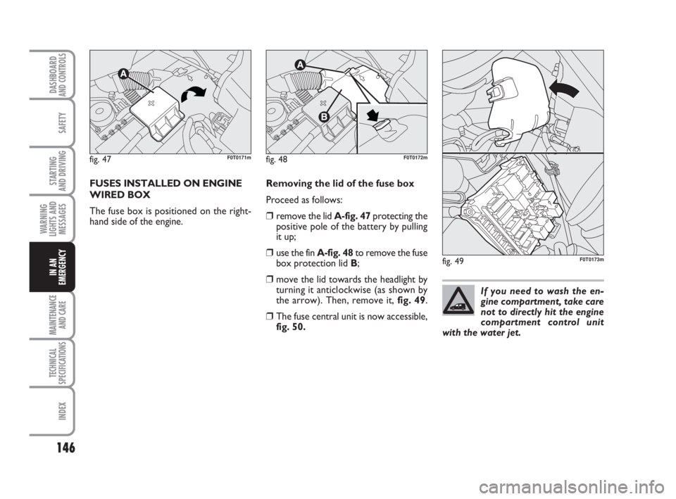
FUSES INSTALLED ON ENGINE
WIRED BOX
The fuse box is positioned on the right-
hand side of the engine.Removing the lid of the fuse box
Proceed as follows:
❒remove the lid A-fig. 47protecting the
positive pole of the battery by pulling
it up;
❒use the fin A-fig. 48to remove the fuse
box protection lid B;
❒move the lid towards the headlight by
turning it anticlockwise (as shown by
the arrow). Then, remove it, fig. 49.
❒The fuse central unit is now accessible,
fig. 50.
fig. 47F0T0171mfig. 48F0T0172m
fig. 49F0T0173m
If you need to wash the en-
gine compartment, take care
not to directly hit the engine
compartment control unit
with the water jet.
123-154 Fiorino GB 1ed:123-154 Fiorino GB 1ed 3-12-2009 15:33 Pagina 146