clock FIAT FIORINO 2014 Owner handbook (in English)
[x] Cancel search | Manufacturer: FIAT, Model Year: 2014, Model line: FIORINO, Model: FIAT FIORINO 2014Pages: 210, PDF Size: 4.9 MB
Page 17 of 210
16
SAFETY
STARTING
AND DRIVING
WARNING
LIGHTS AND
MESSAGES
IN AN
EMERGENCY
MAINTENANCE
AND CARE
TECHNICAL
SPECIFICATIONS
INDEX
DASHBOARD
AND CONTROLS
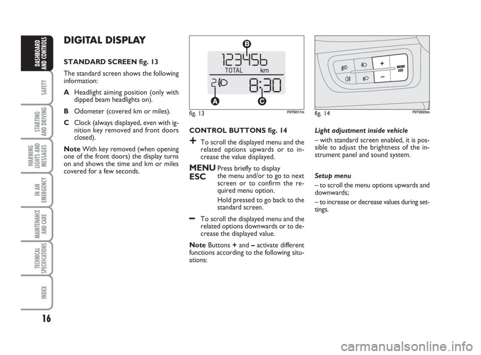
CONTROL BUTTONS fig. 14
+To scroll the displayed menu and the
related options upwards or to in-
crease the value displayed.
MENUPress briefly to display
ESCthe menu and/or to go to next
screen or to confirm the re-
quired menu option.
Hold pressed to go back to the
standard screen.
–To scroll the displayed menu and the
related options downwards or to de-
crease the displayed value.
NoteButtons +and –activate different
functions according to the following situ-
ations: Light adjustment inside vehicle
– with standard screen enabled, it is pos-
sible to adjust the brightness of the in-
strument panel and sound system.
Setup menu
– to scroll the menu options upwards and
downwards;
– to increase or decrease values during set-
tings.
DIGITAL DISPLAY
STANDARD SCREEN fig. 13
The standard screen shows the following
information:
AHeadlight aiming position (only with
dipped beam headlights on).
BOdometer (covered km or miles).
CClock (always displayed, even with ig-
nition key removed and front doors
closed).
NoteWith key removed (when opening
one of the front doors) the display turns
on and shows the time and km or miles
covered for a few seconds.
fig. 13F0T0017mfig. 14F0T0025m
001-035 Fiorino GB 1ed:001-035 Fiorino GB 1ed 2-12-2009 16:14 Pagina 16
Page 18 of 210
17
SAFETY
STARTING
AND DRIVING
WARNING
LIGHTS AND
MESSAGES
IN AN
EMERGENCY
MAINTENANCE
AND CARE
TECHNICAL
SPECIFICATIONS
INDEX
DASHBOARD
AND CONTROLS
SETUP MENU fig. 15
The menu comprises a series of functions
arranged in a cycle which can be selected
through buttons +and –, thus gaining ac-
cess to the different select and setting (set-
up) operations given in the following para-
graphs.
The setup menu can be activated by briefly
pressing button MENU ESC.
Single presses on buttons +and –will
scroll the setup menu options.
Handling modes differ with each other ac-
cording to the characteristic of the option
selected.Selecting a menu option
– briefly press button MENU ESCto se-
lect the menu option to set;
– press buttons +and –(by single press-
es) to select the new setting;
– briefly press button MENU ESCto
store the new setting and go back to the
previously selected menu option.
Selecting “Set Clock”
– briefly press button MENU ESCto se-
lect the first value to change (hours);
– press buttons +and –(by single press-
es) to select the new setting;
– briefly press button MENU ESCto
store the new setting and go to the next
setup menu option (minutes);
– after setting the values with the same
procedure, go back to the menu item pre-
viously selected.Prolonged pressing of MENU ESC button
– to quit the setup menu if you are in the
menu;
– to quit the displayed menu if you are set-
ting an option;
– to save the changes to stored settings (and
confirmed by pressing button MENU
ESC).
The setup menu environment is timed;
when quitting the menu due to timing ex-
piry, only the settings stored by the user
are saved (and confirmed by briefly press-
ing button MENU ESC).
001-035 Fiorino GB 1ed:001-035 Fiorino GB 1ed 2-12-2009 16:14 Pagina 17
Page 20 of 210
19
SAFETY
STARTING
AND DRIVING
WARNING
LIGHTS AND
MESSAGES
IN AN
EMERGENCY
MAINTENANCE
AND CARE
TECHNICAL
SPECIFICATIONS
INDEX
DASHBOARD
AND CONTROLS
Setting the speed limit (SPEEd)
This function is used to set the vehicle
speed limit (km/h or mph); when this lim-
it is exceeded the driver is immediately
alerted (see section “Warning lights and
messages”).
To set the speed limit, proceed as follows:
– briefly press button MENU ESC, the
message (SPEEd) and the previously set
unit (km/h) or (mph) will appear on the
display;
– press button+or –to select speed lim-
it activation (On) or deactivation (OFF);
– if the function has been activated (On),
press buttons +or –to select the re-
quired speed limit and then press MENU
ESCto confirm;
NoteThe speed may be set in the range
from 30 to 200 km/h, or from 20 to 125
mph according to the previously chosen
unit (see “Setting the distance unit”) de-
scribed below. The setting will in-
crease/decrease by five units each time
button +/–is pressed. Hold button +/–
pressed to increase/decrease the setting
rapidly. When close to the desired value,
press the button as many times as re-
quired to complete the regulation.– Briefly press button MENU ESCto go
back to the menu screen or press the but-
ton for long to go back to the standard
screen without storing settings.
To cancel the setting, proceed as follows:
– briefly press button MENU ESC: (On)
will flash on the display;
– press button –: (Off) will flash on the dis-
play;
– briefly press button MENU ESCto go
back to the menu screen or press the but-
ton for long to go back to the standard
screen without storing settings.
Setting the clock (Hour)
With this function it is possible to set the
clock.
To set the required unit proceed as fol-
lows:
– briefly press button MENU ESC,
“hours” will flash on the display;
– press button +or –for setting;
– briefly press button MENU ESC: the
“minutes” start flashing on the display;
– press the button +or –to set the de-
sired value;
– briefly press button MENU ESCto go
back to the menu screen or press the but-
ton for long to go back to the standard
screen without storing settings.Adjusting the buzzer volume
(bUZZ)
This function is used to adjust the volume
of the buzzer triggering in the event of fail-
ure/warning indications and when MENU
ESC,+and –buttons are pressed.
To adjust the desired volume proceed as
follows:
– briefly press button MENU ESC, the
display will show the wording (bUZZ);
– press button +or –to select the re-
quired volume (volume can be adjusted ac-
cording to 8 levels).
– briefly press button MENU ESCto go
back to the menu screen or press the but-
ton for long to go back to the standard
screen without storing settings.
001-035 Fiorino GB 1ed:001-035 Fiorino GB 1ed 2-12-2009 16:14 Pagina 19
Page 22 of 210
21
SAFETY
STARTING
AND DRIVING
WARNING
LIGHTS AND
MESSAGES
IN AN
EMERGENCY
MAINTENANCE
AND CARE
TECHNICAL
SPECIFICATIONS
INDEX
DASHBOARD
AND CONTROLS
MULTIFUNCTIONAL
DISPLAY
(for versions/markets, where provided)
The vehicle can be equipped with a mul-
tifunctional display that, according to the
settings made, will show useful informa-
tion when driving.
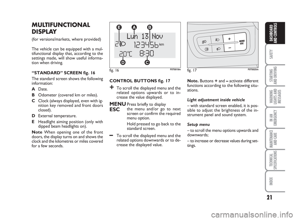
“STANDARD” SCREEN fig. 16
The standard screen shows the following
information:
ADate.
BOdometer (covered km or miles).
CClock (always displayed, even with ig-
nition key removed and front doors
closed).
DExternal temperature.
EHeadlight aiming position (only with
dipped beam headlights on).
NoteWhen opening one of the front
doors, the display turns on and shows the
clock and the kilometres or miles covered
for a few seconds.
fig. 16F0T0019mfig. 17F0T0025m
CONTROL BUTTONS fig. 17
+To scroll the displayed menu and the
related options upwards or to in-
crease the value displayed.
MENUPress briefly to display
ESCthe menu and/or go to next
screen or confirm the required
menu option.
Hold pressed to go back to the
standard screen.
–To scroll the displayed menu and the
related options downwards or to de-
crease the displayed value.Note.Buttons +and –activate different
functions according to the following situ-
ations.
Light adjustment inside vehicle
– with standard screen enabled, it is pos-
sible to adjust the brightness of the in-
strument panel and sound system.
Setup menu
– to scroll the menu options upwards and
downwards;
– to increase or decrease values during set-
tings.
001-035 Fiorino GB 1ed:001-035 Fiorino GB 1ed 2-12-2009 16:14 Pagina 21
Page 23 of 210
22
SAFETY
STARTING
AND DRIVING
WARNING
LIGHTS AND
MESSAGES
IN AN
EMERGENCY
MAINTENANCE
AND CARE
TECHNICAL
SPECIFICATIONS
INDEX
DASHBOARD
AND CONTROLS
Selecting an option of the main menu
with submenu
– Briefly press the button MENU ESCto
display the first submenu option.
– Press buttons +or –(by single press-
es) to scroll all the submenu options.
– Briefly press the button MENU ESCto
select the displayed submenu option and
open the relevant setup menu.
– Press buttons +or –(by single press-
es) to select the new setting for this sub-
menu option.
– Briefly press the button MENU ESC to
store the new setting and go back to the
previously selected submenu option. SETUP MENU fig. 18
The menu comprises a series of functions
arranged in a cycle which can be selected
through buttons +and –, thus gaining ac-
cess to the different select and setting (set-
up) operations given in the following para-
graphs. A submenu is provided for some
items (Clock and Unit setting).
The setup menu can be activated by briefly
pressing button MENU ESC.
Single presses on buttons +or –will scroll
the setup menu options.
Handling modes are different according to
the characteristic of the option selected.
Selecting an option of the main menu
without submenu
– Briefly press the button MENU ESCto
select the main menu option to set.
– Press buttons +or –(by single press-
es) to select the new setting.
– Briefly press the button MENU ESCto
store the new setting and go back to the
main menu option previously selected.Selecting the “Set Date” and “Set time”
– Briefly press button MENU ESCto se-
lect the first value to change (e.g. hours
/minutes or year / month / day).
– Press buttons +or –(by single press-
es) to select the new setting.
– Briefly press button MENU ESCto
store the new setting and go to the next
setup menu option: if this is the last one you
will go back to the previously selected op-
tion of the main menu.
Prolonged pressing of MENU ESC button
– to quit the setup menu if you are in the
main menu;
– to quit the main menu if you are in an-
other point of the menu (e.g.: at submenu
option setting level, at submenu level or
at main menu option setting level);
– to save the changes to stored settings (and
confirmed by pressing button MENU
ESC).
The setup menu environment is timed;
when quitting the menu due to timing ex-
piry, only the settings stored by the user
are saved (and confirmed by briefly press-
ing button MENU ESC).
001-035 Fiorino GB 1ed:001-035 Fiorino GB 1ed 2-12-2009 16:14 Pagina 22
Page 26 of 210
25
SAFETY
STARTING
AND DRIVING
WARNING
LIGHTS AND
MESSAGES
IN AN
EMERGENCY
MAINTENANCE
AND CARE
TECHNICAL
SPECIFICATIONS
INDEX
DASHBOARD
AND CONTROLS
– when accessing the “Mode” submenu:
briefly press button MENU ESC : the
previously set display mode will flash on
the display;
– press button +or –to select “24h” or
“12h”.
When you have made the required set-
tings, briefly press button MENU ESC
to go back to the menu screen or press
the button for long to go back to the stan-
dard screen without storing settings.
– hold MENU ESCpressed to go back
to the standard screen or main menu ac-
cording to the points of the menu where
you are at. Setting the clock (Set time)
This function enables clock setting using
two submenus: “Time” and “Mode”.
Proceed as follows:
– briefly press button MENU ESC, the
display will show the two sub-menus
“Time” and “Mode”;
– press button +or –to surf the two sub-
menus;
– select the required option and then
press button MENU ESC briefly;
– when accessing the “Hour” submenu:
briefly press button MENU ESC, the
“hours” will flash on the display;
– press button +or –for setting;
– briefly press button MENU ESC, the
“minutes” will flash on the display;
– press button +or –for setting;Set date (Set date)
This function enables updating the date
(day - month - year).
To update the date proceed as follows:
– briefly press button MENU ESC: “day”
will flash on the display;
– press button +or –for setting;
– briefly press button MENU ESC:
“month” will flash on the display;
– press button +or –for setting;
– briefly press button MENU ESC:
“year” will flash on the display;
– press button +or –for setting.
NoteThe setting increases or decreases
by one unit each time button +or – is
pressed. Hold the button pressed to in-
crease/decrease the setting rapidly. Com-
plete the setting by briefly pressing the
button when the required setting is ap-
proached.
– Briefly press button MENU ESCto go
back to the menu screen or press the but-
ton for long to go back to the standard
screen without storing settings.
001-035 Fiorino GB 1ed:001-035 Fiorino GB 1ed 2-12-2009 16:14 Pagina 25
Page 60 of 210
59
SAFETY
STARTING
AND DRIVING
WARNING
LIGHTS AND
MESSAGES
IN AN
EMERGENCY
MAINTENANCE
AND CARE
TECHNICAL
SPECIFICATIONS
INDEX
DASHBOARD
AND CONTROLS
DOORS
CENTRAL DOOR
LOCKING/UNLOCKING SYSTEM
Door locking from the outside
The doors will be locked only if all doors
are closed. If one or more than one door
is open after the button on the remote
control Áis pressed, the direction indica-
tors start flashing quickly for approx. 3 sec-
onds. When the metal insert is turned
clockwise in the driver’s door lock all the
doors can be locked.
Quickly double click the button Á
on the
remote control to activate the dead lock
device (see paragraph “Dead lock de-
vice”).
Door unlocking from the outside
Press the button Æbriefly to unlock the
front doors only remotely (Cargo ver-
sion), press the button
∞briefly to un-
lock the load compartment (Cargo ver-
sion). Press the button Æbriefly to unlock all
the doors (Combi version), switch on the
ceiling lights in a timed manner and flash
the direction indicators. All the doors are
unlocked by turning the metal insert in the
door lock on the driver’s side anticlock-
wise.
Unlocking the load compartment
from inside the vehicle
(Cargo version)
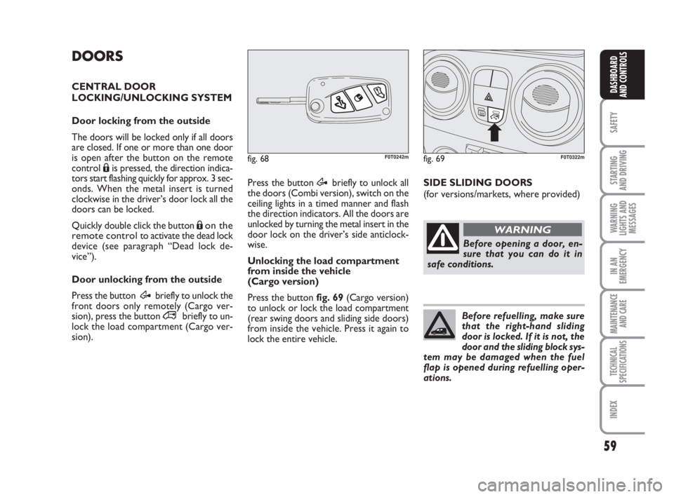
Press the button fig. 69(Cargo version)
to unlock or lock the load compartment
(rear swing doors and sliding side doors)
from inside the vehicle. Press it again to
lock the entire vehicle.
fig. 69F0T0322mfig. 68F0T0242m
SIDE SLIDING DOORS
(for versions/markets, where provided)
Before opening a door, en-
sure that you can do it in
safe conditions.
WARNING
Before refuelling, make sure
that the right-hand sliding
door is locked. If it is not, the
door and the sliding block sys-
tem may be damaged when the fuel
flap is opened during refuelling oper-
ations.
036-082 Fiorino GB 1ed:036-082 Fiorino GB 1ed 30-11-2009 15:47 Pagina 59
Page 82 of 210
81
SAFETY
STARTING
AND DRIVING
WARNING
LIGHTS AND
MESSAGES
IN AN
EMERGENCY
MAINTENANCE
AND CARE
TECHNICAL
SPECIFICATIONS
INDEX
DASHBOARD
AND CONTROLS
DIESEL ENGINES
Operation at low temperatures
If the outside temperature is very low, the
diesel thickens due to the formation of
paraffin clots with consequent anomalous
operation of the fuel supply system.
In order to avoid these problems, different
types of diesel are distributed according to
the season: summer type, winter type and
arctic type (cold, mountain areas). If refu-
elling with diesel fuel whose features are not
suitable to the temperature of use, it is ad-
visable to mix TUTELA DIESEL ART addi-
tive in the proportions shown on the con-
tainer with the fuel. Pour the additive in-
to the tank before the fuel.
When using or parking the vehicle for a
long time in the mountains or cold areas,
it is advisable to refuel using locally avail-
able fuel.
In this case, it is also advisable to keep the
tank over 50% full.For diesel engines, use diesel
fuel for motor vehicles com-
pliant with EN590 European
specifications only. The use of
other products or mixtures may dam-
age the engine beyond repair and con-
sequently cause lapse of warranty in
relation to the damage caused. If you
accidentally introduce other types of
fuel in the tank, do not start the engine
and empty the tank. If the engine has
run also for a very short time, you will
need to have the entire fuel feed sys-
tem emptied in addition to the tank.
REFUELLING CAPACITY
To fill the tank completely, top-up twice
after the pump switches off. Further top-
ups could cause faults in the fuel feeding
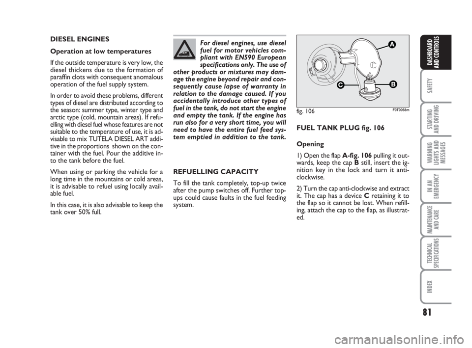
system.FUEL TANK PLUG fig. 106
Opening
1) Open the flap A-fig. 106pulling it out-
wards, keep the cap Bstill, insert the ig-
nition key in the lock and turn it anti-
clockwise.
2) Turn the cap anti-clockwise and extract
it. The cap has a device Cretaining it to
the flap so it cannot be lost. When refill-
ing, attach the cap to the flap, as illustrat-
ed.
fig. 106
C
A
F0T0068m
036-082 Fiorino GB 1ed:036-082 Fiorino GB 1ed 30-11-2009 15:47 Pagina 81
Page 83 of 210
82
SAFETY
STARTING
AND DRIVING
WARNING
LIGHTS AND
MESSAGES
IN AN
EMERGENCY
MAINTENANCE
AND CARE
TECHNICAL
SPECIFICATIONS
INDEX
DASHBOARD
AND CONTROLS
ENVIRONMENTAL
PROTECTION
The devices for curtailing petrol engine
emissions are the following:
❒three-way catalytic converter;
❒Lambda sensors;
❒fuel evaporation prevention system.
In addition, do not let the engine run, even
for a test, with one or more spark plugs
disconnected.
The devices for curtailing diesel fuel en-
gine emissions are the following:
❒oxidising catalytic converter;
❒exhaust gas recirculation system
(E.G.R.);
❒diesel particulate filter (DPF) (for ver-
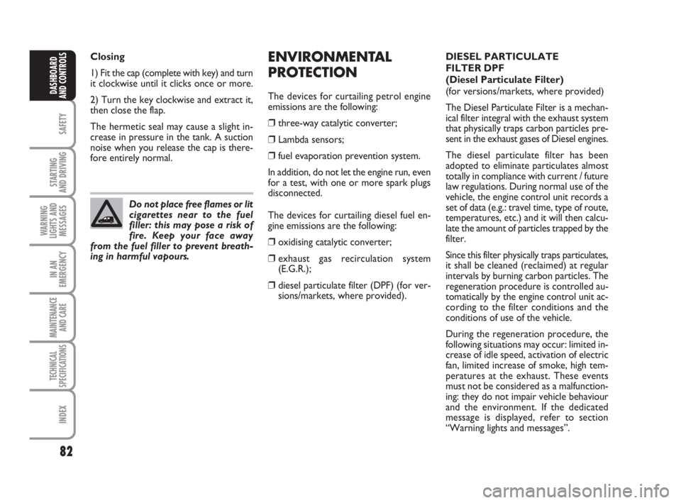
sions/markets, where provided). Do not place free flames or lit
cigarettes near to the fuel
filler: this may pose a risk of
fire. Keep your face away
from the fuel filler to prevent breath-
ing in harmful vapours.
DIESEL PARTICULATE
FILTER DPF
(Diesel Particulate Filter)
(for versions/markets, where provided)
The Diesel Particulate Filter is a mechan-
ical filter integral with the exhaust system
that physically traps carbon particles pre-
sent in the exhaust gases of Diesel engines.
The diesel particulate filter has been
adopted to eliminate particulates almost
totally in compliance with current / future
law regulations. During normal use of the
vehicle, the engine control unit records a
set of data (e.g.: travel time, type of route,
temperatures, etc.) and it will then calcu-
late the amount of particles trapped by the
filter.
Since this filter physically traps particulates,
it shall be cleaned (reclaimed) at regular
intervals by burning carbon particles. The
regeneration procedure is controlled au-
tomatically by the engine control unit ac-
cording to the filter conditions and the
conditions of use of the vehicle.
During the regeneration procedure, the
following situations may occur: limited in-
crease of idle speed, activation of electric
fan, limited increase of smoke, high tem-
peratures at the exhaust. These events
must not be considered as a malfunction-
ing: they do not impair vehicle behaviour
and the environment. If the dedicated
message is displayed, refer to section
“Warning lights and messages”. Closing
1) Fit the cap (complete with key) and turn
it clockwise until it clicks once or more.
2) Turn the key clockwise and extract it,
then close the flap.
The hermetic seal may cause a slight in-
crease in pressure in the tank. A suction
noise when you release the cap is there-
fore entirely normal.
036-082 Fiorino GB 1ed:036-082 Fiorino GB 1ed 30-11-2009 15:47 Pagina 82
Page 134 of 210
133
SAFETY
MAINTENANCE
AND CARE
TECHNICAL
SPECIFICATIONS
INDEX
DASHBOARDAND CONTROLS
STARTING
AND DRIVING
WARNING
LIGHTS AND
MESSAGES
IN AN
EMERGENCY
❒If at least 1.8 bar pressure is read, re-
store proper pressure (with engine
running and handbrake on) and restart.
❒Drive with the utmost care to the near-
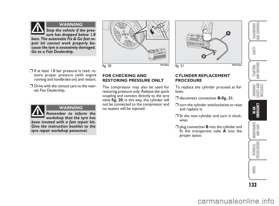
est Fiat Dealership.FOR CHECKING AND
RESTORING PRESSURE ONLY
The compressor may also be used for
restoring pressure only. Release the quick
coupling and connect directly to the tyre
valve fig. 20; in this way, the cylinder will
not be connected to the compressor and
no sealant will be injected. CYLINDER REPLACEMENT
PROCEDURE
To replace the cylinder proceed as fol-
lows:
❒disconnect connection B-fig. 21;
❒turn the cylinder anticlockwise to raise
and replace it;
❒fit the new cylinder and turn it clock-
wise;
❒plug connection Binto the cylinder and
fit the transparent tube Ainto the
proper space.
Stop the vehicle if the pres-
sure has dropped below 1.8
bars. The automatic Fix & Go fast re-
pair kit cannot work properly be-
cause the tyre is excessively damaged.
Go to a Fiat Dealership.
WARNING
Remember to inform the
workshop that the tyre has
been treated with a fast repair kit.
Give the instruction booklet to the
tyre repair workshop personnel.
WARNING
fig. 20F0T192mfig. 21F0T0132m
123-154 Fiorino GB 1ed:123-154 Fiorino GB 1ed 3-12-2009 15:33 Pagina 133