stop start FIAT FIORINO 2019 Owner handbook (in English)
[x] Cancel search | Manufacturer: FIAT, Model Year: 2019, Model line: FIORINO, Model: FIAT FIORINO 2019Pages: 220, PDF Size: 6.22 MB
Page 102 of 220
16)There must therefore always be
enough petrol in the tank to protect the
petrol pump and to guarantee temporary
switching from methane to petrol
operation, if high performance is required.
17)If the engine fails to start with a gear
engaged, the potentially dangerous
situation due to the fact that the gearbox is
automatically placed in neutral will be
signalled by a buzzer.
18)Never, under any circumstances, jump
start the engine by pushing, towing or
coasting downhill. This could cause fuel to
flow into the catalytic converter and
damage it beyond repair.
19)A quick burst on the accelerator before
stopping the engine serves no practical
purpose; it wastes fuel and is especially
damaging to turbocharged engines.HANDBRAKE
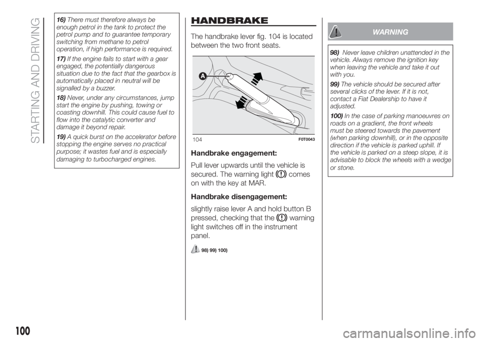
The handbrake lever fig. 104 is located
between the two front seats.
Handbrake engagement:
Pull lever upwards until the vehicle is
secured. The warning light
comes
on with the key at MAR.
Handbrake disengagement:
slightly raise lever A and hold button B
pressed, checking that the
warning
light switches off in the instrument
panel.
98) 99) 100)
WARNING
98)Never leave children unattended in the
vehicle. Always remove the ignition key
when leaving the vehicle and take it out
with you.
99)The vehicle should be secured after
several clicks of the lever. If it is not,
contact a Fiat Dealership to have it
adjusted.
100)In the case of parking manoeuvres on
roads on a gradient, the front wheels
must be steered towards the pavement
(when parking downhill), or in the opposite
direction if the vehicle is parked uphill. If
the vehicle is parked on a steep slope, it is
advisable to block the wheels with a wedge
or stone.
104F0T0043
100
STARTING AND DRIVING
Page 103 of 220
PARKING THE
VEHICLE
101)
Proceed as follows when parking and
leaving the vehicle:
engage a gear (1stgear if facing
uphill or reverse if facing downhill) and
leave the wheels turned;
stop the engine and engage the
handbrake;
always remove the ignition key.
If the vehicle is parked on a steep
slope, it is advisable to block the
wheels with a wedge or stone.
Do not leave the key in the MAR
position to prevent the battery from
running down.
Versions with COMFORT-MATIC
transmission
To park safely, keeping a foot on the
brake pedal, the 1
stor reverse (R) gear
must be engaged and, in case of
parking uphills/downhills, the
handbrake must be engaged.
IMPORTANT NEVER leave the vehicle
with the transmission in neutral (N)
or, on versions equipped with automatic
(Comfort matic) transmission, before
putting the shift lever in thePposition.IMPORTANT NOTES
With the vehicle stationary and a
gear engaged, always keep the brake
pedal pressed until you decide to
set off, then release the brake and
accelerate gently;
during prolonged stops with the
engine running, it is advisable to keep
the gearbox in neutral (N);
In order to safeguard the efficiency
of the clutch, do not use the
accelerator to keep the vehicle
stationary (e.g. when stopped on an
incline);
the clutch could overheat and be
damaged; use the brake pedal and only
operate the accelerator pedal when
you decide to set off;
only use second gear when you
need greater control for starting
manoeuvres on surfaces with poor grip;
if, with reverse gear (R) engaged,
you have to engage first gear or vice
versa, only do this when the vehicle is
completely stationary and with the
brake pedal pressed;
although it is strongly inadvisable, if
you are driving downhill and, for
unexpected reasons, you let the vehicle
move forward with the transmission in
neutral (N), when you engage a gear,
the system will automatically engage
the best gear to transmit the correct
drive torque to the wheels depending
on the vehicle's speed;
WARNING
101)Never leave children unattended in
the vehicle. Always remove the ignition key
when leaving the vehicle and take it out
with you.
101
Page 108 of 220

PARKING SENSORS
(for versions/markets, where provided)
105)
22) 23) 24)
The parking sensors, located in the rear
bumper fig. 113 , are used to detect
the presence of any obstacles near the
rear part of the vehicle. The sensors
by means of intermittent acoustic
indication warn the driver of the
presence of obstacles.
ACTIVATION/
DEACTIVATION
The sensors are automatically activated
when reverse gear is engaged.
The buzzer becomes more frequent as
the obstacle behind the vehicle gets
closer to the bumper.ACOUSTIC SIGNAL
When reverse gear is engaged an
intermittent acoustic signal is
automatically activated.
The frequency of the acoustic warning:
increases as the distance between
the vehicle and the obstacle decreases;
become continuous when the
distance between the vehicle and the
obstacle is less than 30 cm and stop
immediately if the distance increases;
it remains constant if the distance
remains unchanged; if this situation
concerns the side sensors, the buzzer
will stop after about 3 seconds to
avoid, for example, warning indications
in the event of manoeuvres along
walls.
Detection distances
If several obstacles are detected by the
sensors, only the nearest one is
considered.
FAULT INDICATIONS
Any parking sensor failures will be
indicated when engaging reverse by the
warning light
in the instrument
panel together with the message in the
multifunction display (for versions/
markets where provided) (see “Warning
lights and messages” section in the
"Knowing the instrument panel"
chapter).OPERATION WITH A
TRAILER
The operation of the sensors is
automatically deactivated when the
trailer's electrical connection is inserted
in the vehicle tow hook socket. Sensors
are reactivated on removing the
trailer's electrical connection.
IMPORTANT NOTES
During parking manoeuvres, pay the
utmost attention to any obstacles that
could be located above or below the
sensors.
Sometimes, objects located very
near the rear of the vehicle are not
detected and could therefore damage
the vehicle or be damaged themselves.
The signals sent out by the sensors
can be altered by dirt, snow or ice
deposited on the sensors or by
ultrasound systems (e.g. truck
pneumatic brakes or pneumatic drills)
near the vehicle.
The parking sensors work properly
with the swing doors closed. If they are
open, they can cause the system to
send false signals: always close the rear
doors.
Also, do not apply stickers to the
sensors.
113F0T0155
106
STARTING AND DRIVING
Page 110 of 220
Start&Stop SYSTEM
(for versions/markets, where provided)
106) 107) 108) 109)
IN BRIEF
The Start&Stop device automatically
stops the engine each time the
vehicle is stationary and all the
conditions for automatic switch-off
have been met, and starts it again
when the driver wants to move off.
This improves the efficiency of the
vehicle by reducing fuel consumption,
the emission of harmful gases and
noise pollution.
OPERATING MODE
Stopping the engine
Versions with manual transmission
With the vehicle stationary, the engine
stops with the gearbox in neutral and
the clutch pedal released.Versions with Comfort-matic
transmission
With the vehicle stationary and the
brake pedal pressed, the engine stops
if the gear lever is in position other
thanR. In the event of stops uphill,
engine switching off is disabled to make
the "Hill Holder" function available
(works only with the engine running).
The warning light on the instrument
panel switches on to signal that the
engine has stopped.
Restarting the engine
Versions with manual transmission
Depress the clutch pedal to restart
the engine.
Versions with Comfort-matic
transmission
Releasing the brake pedal the engine
restarts automatically; the icon switches
off on the display. If the engine is
restarted with the “Hill Holder” function
off, move the lever towards (+), (-)or
Rand the engine restarts.MANUAL ACTIVATION
AND DEACTIVATION
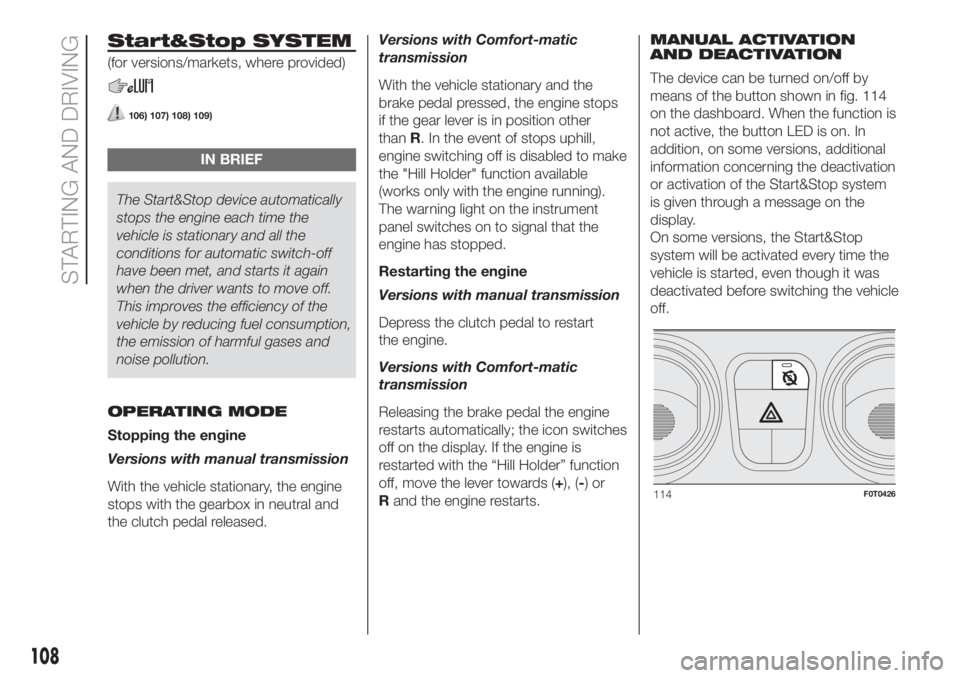
The device can be turned on/off by
means of the button shown in fig. 114
on the dashboard. When the function is
not active, the button LED is on. In
addition, on some versions, additional
information concerning the deactivation
or activation of the Start&Stop system
is given through a message on the
display.
On some versions, the Start&Stop
system will be activated every time the
vehicle is started, even though it was
deactivated before switching the vehicle
off.
114F0T0426
108
STARTING AND DRIVING
Page 111 of 220
SAFETY FUNCTIONS
In engine cut-out conditions through
the Start&Stop system, if the driver
unfastens his/her seat belt and opens
the driver's door or the passenger door,
the engine can be restarted only by
using the key. The driver is notified of
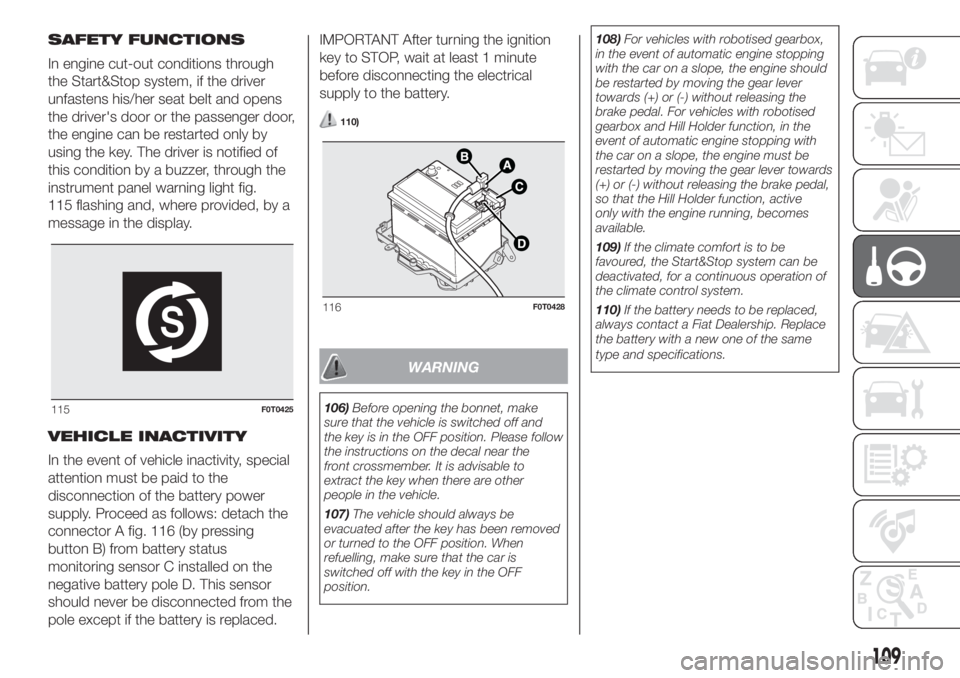
this condition by a buzzer, through the
instrument panel warning light fig.
115 flashing and, where provided, by a
message in the display.
VEHICLE INACTIVITY
In the event of vehicle inactivity, special
attention must be paid to the
disconnection of the battery power
supply. Proceed as follows: detach the
connector A fig. 116 (by pressing
button B) from battery status
monitoring sensor C installed on the
negative battery pole D. This sensor
should never be disconnected from the
pole except if the battery is replaced.IMPORTANT After turning the ignition
key to STOP, wait at least 1 minute
before disconnecting the electrical
supply to the battery.
110)
WARNING
106)Before opening the bonnet, make
sure that the vehicle is switched off and
the key is in the OFF position. Please follow
the instructions on the decal near the
front crossmember. It is advisable to
extract the key when there are other
people in the vehicle.
107)The vehicle should always be
evacuated after the key has been removed
or turned to the OFF position. When
refuelling, make sure that the car is
switched off with the key in the OFF
position.108)For vehicles with robotised gearbox,
in the event of automatic engine stopping
with the car on a slope, the engine should
be restarted by moving the gear lever
towards (+) or (-) without releasing the
brake pedal. For vehicles with robotised
gearbox and Hill Holder function, in the
event of automatic engine stopping with
the car on a slope, the engine must be
restarted by moving the gear lever towards
(+) or (-) without releasing the brake pedal,
so that the Hill Holder function, active
only with the engine running, becomes
available.
109)If the climate comfort is to be
favoured, the Start&Stop system can be
deactivated, for a continuous operation of
the climate control system.
110)If the battery needs to be replaced,
always contact a Fiat Dealership. Replace
the battery with a new one of the same
type and specifications.115F0T0425
116F0T0428
109
Page 113 of 220
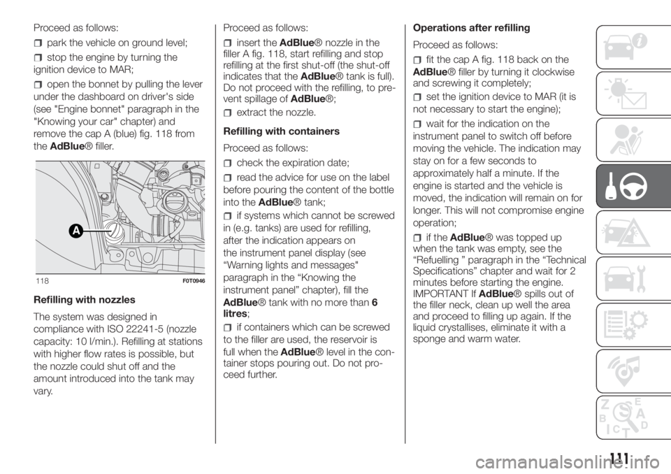
Proceed as follows:
park the vehicle on ground level;
stop the engine by turning the
ignition device to MAR;
open the bonnet by pulling the lever
under the dashboard on driver's side
(see "Engine bonnet" paragraph in the
"Knowing your car" chapter) and
remove the cap A (blue) fig. 118 from
theAdBlue® filler.
Refilling with nozzles
The system was designed in
compliance with ISO 22241-5 (nozzle
capacity: 10 l/min.). Refilling at stations
with higher flow rates is possible, but
the nozzle could shut off and the
amount introduced into the tank may
vary.Proceed as follows:
insert theAdBlue® nozzle in the
filler A fig. 118, start refilling and stop
refilling at the first shut-off (the shut-off
indicates that theAdBlue® tank is full).
Do not proceed with the refilling, to pre-
vent spillage ofAdBlue®;
extract the nozzle.
Refilling with containers
Proceed as follows:
check the expiration date;
read the advice for use on the label
before pouring the content of the bottle
into theAdBlue® tank;
if systems which cannot be screwed
in (e.g. tanks) are used for refilling,
after the indication appears on
the instrument panel display (see
“Warning lights and messages"
paragraph in the “Knowing the
instrument panel” chapter), fill the
AdBlue® tank with no more than
litres;
if containers which can be screwed
to the filler are used, the reservoir is
full when theAdBlue® level in the con-
tainer stops pouring out. Do not pro-
ceed further.Operations after refilling
Proceed as follows:
fit the cap A fig. 118 back on the
AdBlue® filler by turning it clockwise
and screwing it completely;
set the ignition device to MAR (it is
not necessary to start the engine);
wait for the indication on the
instrument panel to switch off before
moving the vehicle. The indication may
stay on for a few seconds to
approximately half a minute. If the
engine is started and the vehicle is
moved, the indication will remain on for
longer. This will not compromise engine
operation;
if theAdBlue® was topped up
when the tank was empty, see the
“Refuelling ” paragraph in the “Technical
Specifications” chapter and wait for 2
minutes before starting the engine.
IMPORTANT IfAdBlue® spills out of
the filler neck, clean up well the area
and proceed to filling up again. If the
liquid crystallises, eliminate it with a
sponge and warm water.A
118F0T0946
111
6
Page 124 of 220
FIX&GO
AUTOMATIC KIT
121) 122)
30)
The Fix&Go automatic quick tyre repair
kit is located in a special container in
the boot.
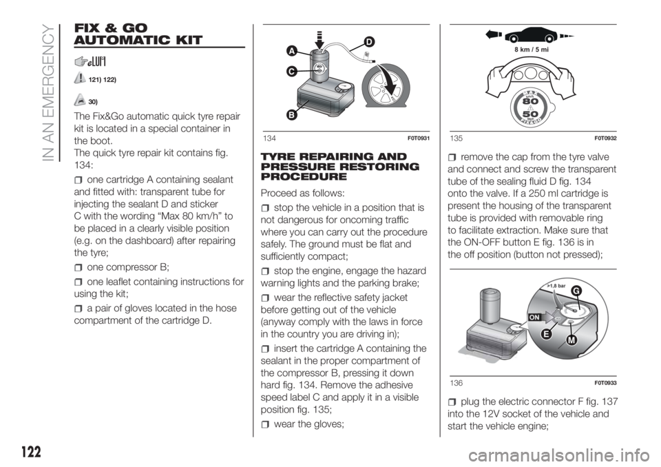
The quick tyre repair kit contains fig.
134:
one cartridge A containing sealant
and fitted with: transparent tube for
injecting the sealant D and sticker
C with the wording “Max 80 km/h” to
be placed in a clearly visible position
(e.g. on the dashboard) after repairing
the tyre;
one compressor B;
one leaflet containing instructions for
using the kit;
a pair of gloves located in the hose
compartment of the cartridge D.TYRE REPAIRING AND
PRESSURE RESTORING
PROCEDURE
Proceed as follows:
stop the vehicle in a position that is
not dangerous for oncoming traffic
where you can carry out the procedure
safely. The ground must be flat and
sufficiently compact;
stop the engine, engage the hazard
warning lights and the parking brake;
wear the reflective safety jacket
before getting out of the vehicle
(anyway comply with the laws in force
in the country you are driving in);
insert the cartridge A containing the
sealant in the proper compartment of
the compressor B, pressing it down
hard fig. 134. Remove the adhesive
speed label C and apply it in a visible
position fig. 135;
wear the gloves;
remove the cap from the tyre valve
and connect and screw the transparent
tube of the sealing fluid D fig. 134
onto the valve. If a 250 ml cartridge is
present the housing of the transparent
tube is provided with removable ring
to facilitate extraction. Make sure that
the ON-OFF button E fig. 136 is in
the off position (button not pressed);
plug the electric connector F fig. 137
into the 12V socket of the vehicle and
start the vehicle engine;
A
C
B
D
134F0T0931
8 km / 5 mi
135F0T0932
EM
G
136F0T0933
122
IN AN EMERGENCY
Page 125 of 220
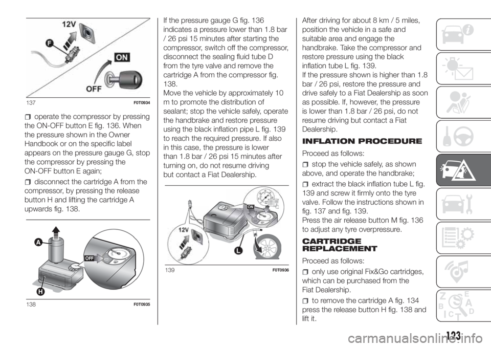
operate the compressor by pressing
the ON-OFF button E fig. 136. When
the pressure shown in the Owner
Handbook or on the specific label
appears on the pressure gauge G, stop
the compressor by pressing the
ON-OFF button E again;
disconnect the cartridge A from the
compressor, by pressing the release
button H and lifting the cartridge A
upwards fig. 138.If the pressure gauge G fig. 136
indicates a pressure lower than 1.8 bar
/ 26 psi 15 minutes after starting the
compressor, switch off the compressor,
disconnect the sealing fluid tube D
from the tyre valve and remove the
cartridge A from the compressor fig.
138.
Move the vehicle by approximately 10
m to promote the distribution of
sealant; stop the vehicle safely, operate
the handbrake and restore pressure
using the black inflation pipe L fig. 139
to reach the required pressure. If also
in this case, the pressure is lower
than 1.8 bar / 26 psi 15 minutes after
turning on, do not resume driving
but contact a Fiat Dealership.After driving for about 8 km / 5 miles,
position the vehicle in a safe and
suitable area and engage the
handbrake. Take the compressor and
restore pressure using the black
inflation tube L fig. 139.
If the pressure shown is higher than 1.8
bar / 26 psi, restore the pressure and
drive safely to a Fiat Dealership as soon
as possible. If, however, the pressure
is lower than 1.8 bar / 26 psi, do not
resume driving but contact a Fiat
Dealership.
INFLATION PROCEDURE
Proceed as follows:
stop the vehicle safely, as shown
above, and operate the handbrake;
extract the black inflation tube L fig.
139 and screw it firmly onto the tyre
valve. Follow the instructions shown in
fig. 137 and fig. 139.
Press the air release button M fig. 136
to adjust any tyre overpressure.
CARTRIDGE
REPLACEMENT
Proceed as follows:
only use original Fix&Go cartridges,
which can be purchased from the
Fiat Dealership.
to remove the cartridge A fig. 134
press the release button H fig. 138 and
lift it.
137F0T0934
A
H
138F0T0935
139F0T0936
123
Page 137 of 220
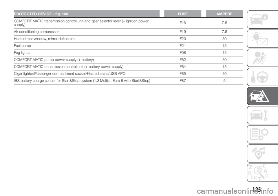
PROTECTED DEVICE - fig. 166 FUSE AMPERE
COMFORT-MATIC transmission control unit and gear selector lever (+ ignition power
supply)F16 7.5
Air conditioning compressorF19 7.5
Heated rear window, mirror defrosters F20 30
Fuel pumpF21 15
Fog lightsF08 15
COMFORT-MATIC pump power supply (+ battery) F82 30
COMFORT-MATIC transmission control unit (+ battery power supply) F84 15
Cigar lighter/Passenger compartment socket/Heated seats/USB APO F85 30
IBS battery charge sensor for Start&Stop system (1.3 Multijet Euro 6 with Start&Stop) F87 5
135
Page 143 of 220
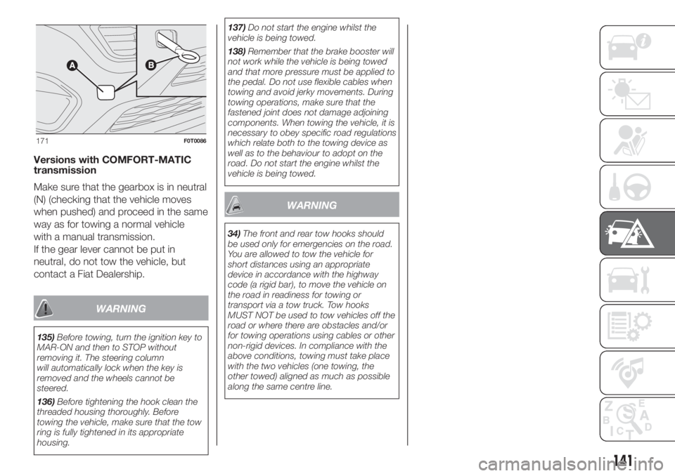
Versions with COMFORT-MATIC
transmission
Make sure that the gearbox is in neutral
(N) (checking that the vehicle moves
when pushed) and proceed in the same
way as for towing a normal vehicle
with a manual transmission.
If the gear lever cannot be put in
neutral, do not tow the vehicle, but
contact a Fiat Dealership.
WARNING
135)Before towing, turn the ignition key to
MAR-ON and then to STOP without
removing it. The steering column
will automatically lock when the key is
removed and the wheels cannot be
steered.
136)Before tightening the hook clean the
threaded housing thoroughly. Before
towing the vehicle, make sure that the tow
ring is fully tightened in its appropriate
housing.137)Do not start the engine whilst the
vehicle is being towed.
138)Remember that the brake booster will
not work while the vehicle is being towed
and that more pressure must be applied to
the pedal. Do not use flexible cables when
towing and avoid jerky movements. During
towing operations, make sure that the
fastened joint does not damage adjoining
components. When towing the vehicle, it is
necessary to obey specific road regulations
which relate both to the towing device as
well as to the behaviour to adopt on the
road. Do not start the engine whilst the
vehicle is being towed.
WARNING
34)The front and rear tow hooks should
be used only for emergencies on the road.
You are allowed to tow the vehicle for
short distances using an appropriate
device in accordance with the highway
code (a rigid bar), to move the vehicle on
the road in readiness for towing or
transport via a tow truck. Tow hooks
MUST NOT be used to tow vehicles off the
road or where there are obstacles and/or
for towing operations using cables or other
non-rigid devices. In compliance with the
above conditions, towing must take place
with the two vehicles (one towing, the
other towed) aligned as much as possible
along the same centre line.
171F0T0086
141