ECO mode FIAT FREEMONT 2011 Owner handbook (in English)
[x] Cancel search | Manufacturer: FIAT, Model Year: 2011, Model line: FREEMONT, Model: FIAT FREEMONT 2011Pages: 267, PDF Size: 5.16 MB
Page 103 of 267

WINDOWS
POWER WINDOWS
The window controls on the driver's door trim panel
control all of the door windows. (fig. 89)
There are single window controls on each passenger
door trim panel, which operate the passenger door
windows. The window controls will operate when the
ignition is in the ON/RUN or ACC position.
NOTE:For vehicles equipped with the Uconnect
Touch™, the power window switches will remain ac-
tive for up to 10 minutes after the ignition is cycled to
the OFF position. Opening either front door will cancel
this feature. The time is programmable. Refer to
“Uconnect Touch™ Settings” in “Knowing Your Ve-
hicle” for further information.
WARNING!
Never leave children in a vehicle with
the Key Fob. Occupants, particularly un-
attended children, can become entrapped by the
windows while operating the power window
switches. Such entrapment may result in serious
injury or death.
Auto-Down Feature
The driver's power window switch has an Auto-down
feature. Press the window switch past the first detent,
release, and the window will go down automatically.
To open the window part way, press the window
switch to the first detent and release it when you want
the window to stop.
To stop the window from going all the way down during
the Auto-down operation, pull up on the switch briefly.
Auto-Up Feature With Anti-Pinch Protection
— If Equipped
On some models, the driver's and front passenger's
power window switch has an Auto-up feature. Pull the
window switch up to the second detent, release, and
the window will go up automatically.
To stop the window from going all the way up during
the Auto-up operation, push down on the switch
briefly.
(fig. 89) Power Window Switches
96
KNOWING
YOUR
VEHICLE
SAFETY
STARTING AND
DRIVING
WARNING
LIGHTS AND
MESSAGES
IN AN
EMERGENCY
SERVICING AND
CARETECHNICAL
SPECIFICATIONSCONTENTS
Page 108 of 267
WARNING!
The weight and position of cargo and
passengers can change the vehicle cen-
ter of gravity and vehicle handling.To avoid loss of
control resulting in personal injury, follow these
guidelines for loading your vehicle:
• Do not carry loads that exceed the load limits de- scribed on the label attached to the left door or left
door center pillar.
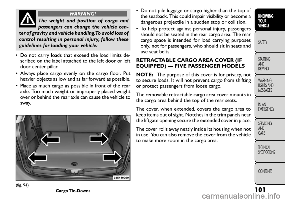
• Always place cargo evenly on the cargo floor. Put heavier objects as low and as far forward as possible.
• Place as much cargo as possible in front of the rear axle. Too much weight or improperly placed weight
over or behind the rear axle can cause the vehicle to
sway. • Do not pile luggage or cargo higher than the top of
the seatback. This could impair visibility or become a
dangerous projectile in a sudden stop or collision.
• To help protect against personal injury, passengers should not be seated in the rear cargo area. The rear
cargo space is intended for load carrying purposes
only, not for passengers, who should sit in seats and
use seat belts.
RETRACTABLE CARGO AREA COVER (IF
EQUIPPED) — FIVE PASSENGER MODELS
NOTE: The purpose of this cover is for privacy, not
to secure loads. It will not prevent cargo from shifting
or protect passengers from loose cargo.
The removable retractable cargo area cover mounts in
the cargo area behind the top of the rear seats.
The cover, when extended, covers the cargo area to
keep items out of sight. Notches in the trim panels near
the liftgate opening secure the extended cover in place.
The cover rolls away neatly inside its housing when not
in use. You can also remove the cover from the vehicle
to make more room in the cargo area.
(fig. 94) Cargo Tie-Downs 101
KNOWING
YOURVEHICLESAFETY
STARTING ANDDRIVING
WARNING
LIGHTS AND
MESSAGES
IN AN
EMERGENCY
SERVICING AND
CARETECHNICAL
SPECIFICATIONSCONTENTS
Page 118 of 267
NOTE:The TSC is disabled when the ESC system is
in the “Partial Off ” mode.
WARNING!
TSC cannot stop all trailers from
swaying. Always use caution when tow-
ing a trailer and follow the tongue weight recom-
mendations. Refer to “Trailer Towing” in “Starting
and Driving” for further information.
If TSC activates while towing a trailer, stop the
vehicle at the nearest safe location and adjust
the trailer load to eliminate the trailer sway.
Failure to follow these warnings can result in an
accident or serious personal injury. ONBOARD DIAGNOSTIC SYSTEM —
OBD II
Your vehicle is equipped with a sophisticated onboard
diagnostic system called OBD II. This system monitors
the performance of the emissions, engine, and auto-
matic transmission control systems. When these sys-
tems are operating properly, your vehicle will provide
excellent performance and fuel economy, as well as
engine emissions well within current government regu-lations.
If any of these systems require service, the OBD II
system will turn on the “Malfunction Indicator Light”
(MIL). It will also store diagnostic codes and other
information to assist your service technician in making
repairs. Although your vehicle will usually be drivable
and not need towing, see your authorized dealer for
service as soon as possible.
Prolonged driving with the MIL on
could cause further damage to the emis-
sion control system. It could also affect
fuel economy and drivability.The vehicle must be
serviced before any emissions tests can be per-
formed.
If the MIL is flashing while the engine is running,
severe catalytic converter damage and power loss
will soon occur. Immediate service is required.
111
KNOWING
YOURVEHICLESAFETY
STARTING ANDDRIVING
WARNING
LIGHTS AND
MESSAGES
IN AN
EMERGENCY
SERVICING AND
CARETECHNICAL
SPECIFICATIONSCONTENTS
Page 131 of 267
WARNING!
Drivers must be careful when backing
up even when using the ParkSense
®
Rear Park Assist system. Always check carefully
behind your vehicle, look behind you, and be sure
to check for pedestrians, animals, other vehicles,
obstructions, and blind spots before backing up.
You are responsible for safety and must continue
to pay attention to your surroundings. Failure to
do so can result in serious injury or death.
Before using the ParkSense
®Rear Park Assist
system, it is strongly recommended that the ball
mount and hitch ball assembly is disconnected
from the vehicle when the vehicle is not used for
towing. Failure to do so can result in injury or
damage to vehicles or obstacles because the
hitch ball will be much closer to the obstacle than
the rear fascia when the warning display turns on
the single flashing arc and sounds the continuous
tone. Also, the sensors could detect the ball
mount and hitch ball assembly, depending on its
size and shape, giving a false indication that an
obstacle is behind the vehicle. PARKVIEW® REAR BACK UP
CAMERA — IF EQUIPPED
Your vehicle may be equipped with the ParkView
®
Rear Back Up Camera that allows you to see an
on-screen image of the rear surroundings of your
vehicle whenever the shift lever is put into REVERSE.
The image will be displayed on the radio touchscreen
display along with a caution note to “check entire
surroundings” across the top of the screen. After five
seconds this note will disappear. The ParkView
®cam-
era is located on the rear of the vehicle above the rear
License plate.
When the vehicle is shifted out of REVERSE, the rear
camera mode is exited and the navigation or audio
screen appears again.
When displayed, static grid lines will illustrate the
width of the vehicle while a dashed center-line will
indicate the center of the vehicle to assist with parking
or aligning to a hitch/receiver. The static grid lines will
show separate zones that will help indicate the dis-
tance to the rear of the vehicle. The following table
shows the approximate distances for each zone:
Zone Distance to the rear of the vehicle
Red 0 - 30 cm
Yellow 30 cm - 1 m
Green 1 m or greater
124
KNOWING YOUR
VEHICLE
SAFETY
STARTING AND
DRIVING
WARNING
LIGHTS AND
MESSAGES
IN AN
EMERGENCY
SERVICING AND
CARETECHNICAL
SPECIFICATIONSCONTENTS
Page 134 of 267

STEERING WHEEL AUDIO
CONTROLS — IF EQUIPPED
The remote sound system controls are located on the
rear surface of the steering wheel. The left and right-
hand controls are rocker-type switches with a pushbut-
ton in the center of each switch. Reach behind the
steering wheel to access the switches. (fig. 108)
RIGHT-HAND SWITCH FUNCTIONS
• Press the top of the switch to increase the volume.
• Press the bottom of the switch to decrease thevolume.
• Press the button in the center of the switch to change modes (i.e., AM, FM, etc.). LEFT-HAND SWITCH FUNCTIONS FOR
RADIO OPERATION
• Press the top of the switch to SEEK the next listen-
able station up from the current setting.
• Press the bottom of the switch to SEEK the next listenable station down from the current setting.
• Press the button in the center of the switch to tune to the next preset that you have programmed.
LEFT-HAND SWITCH FUNCTIONS FOR
MEDIA (I.E., CD) OPERATION
• Press the top of the switch once to listen to the next track.
• Press the bottom of the switch once either to listen to the beginning of the current track or to listen to
the beginning of the previous track if it is within one
second after the current track begins to play.
• Press the switch up or down twice to listen to the second track, three times to listen to the third track,
and so forth.
• Press the button located in the center of the switch to change to the next preset that you have
programmed.(fig. 108)Remote Sound Controls (Back View Of Steering Wheel) 127
KNOWING
YOURVEHICLESAFETY
STARTING ANDDRIVING
WARNING
LIGHTS AND
MESSAGES
IN AN
EMERGENCY
SERVICING AND
CARETECHNICAL
SPECIFICATIONSCONTENTS
Page 144 of 267
SEAT BELTS IN PASSENGER SEATING
POSITIONS
The seat belts in the passenger seating positions are
equipped with an Automatic Locking Retractor (ALR)
or a cinching latch plate which are used to secure a
child restraint system. For additional information refer
to “Installing Child Restraints Using the Vehicle Seat
Belt” under the “Child Restraint” section. The chart
below defines the type of feature for each seatingposition.
Driver Center Passenger
First Row N/A N/A ALR
Second Row ALR ALR ALR
• N/A — Not Applicable
• ALR — Automatic Locking Retractor
If the passenger seating position is equipped with an
ALR and is being used for normal usage:
Only pull the belt webbing out far enough to comfort-
ably wrap around the occupant's mid-section so as to
not activate the ALR. If the ALR is activated, you will
hear a ratcheting sound as the belt retracts. Allow the
webbing to retract completely in this case and then
carefully pull out only the amount of webbing neces-
sary to comfortably wrap around the occupant's mid-
section. Slide the latch plate into the buckle until you
hear a "click." AUTOMATIC LOCKING RETRACTOR MODE
(ALR) — IF EQUIPPED
In this mode, the shoulder belt is automatically pre-
locked. The belt will still retract to remove any slack in
the shoulder belt. The Automatic Locking Mode is
available on all passenger-seating positions with a com-
bination lap/shoulder belt. Use the Automatic Locking
Mode anytime a child safety seat is installed in a seating
position that has a belt with this feature. Children
12 years old and under should always be properly
restrained in the rear seat.
How To Engage The Automatic Locking Mode
1. Buckle the combination lap and shoulder belt.
2. Grasp the shoulder portion and pull downward until
the entire belt is extracted.
3. Allow the belt to retract. As the belt retracts, you will hear a clicking sound. This indicates the safety
belt is now in the Automatic Locking Mode.
How To Disengage The Automatic LockingMode
Unbuckle the combination lap/shoulder belt and allow
it to retract completely to disengage the Automatic
Locking Mode and activate the vehicle sensitive (emer-
gency) locking mode.
137
KNOWING
YOURVEHICLESAFETYSTARTING ANDDRIVING
WARNING
LIGHTS AND
MESSAGES
IN AN
EMERGENCY
SERVICING AND
CARETECHNICAL
SPECIFICATIONSCONTENTS
Page 158 of 267
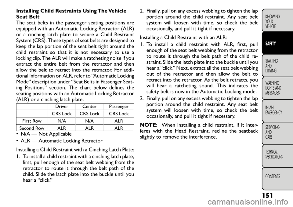
Installing Child Restraints Using The Vehicle
Seat Belt
The seat belts in the passenger seating positions are
equipped with an Automatic Locking Retractor (ALR)
or a cinching latch plate to secure a Child Restraint
System (CRS). These types of seat belts are designed to
keep the lap portion of the seat belt tight around the
child restraint so that it is not necessary to use a
locking clip. The ALR will make a ratcheting noise if you
extract the entire belt from the retractor and then
allow the belt to retract into the retractor. For addi-
tional information on ALR, refer to “Automatic Locking
Mode” description under “Seat Belts in Passenger Seat-
ing Positions” section. The chart below defines the
seating positions with an Automatic Locking Retractor
(ALR) or a cinching latch plate.
Driver Center Passenger
CRS Lock CRS Lock CRS Lock
First Row N/A N/A ALR
Second Row ALR ALR ALR
• N/A — Not Applicable
• ALR — Automatic Locking Retractor
Installing a Child Restraint with a Cinching Latch Plate:
1. To install a child restraint with a cinching latch plate,
first, pull enough of the seat belt webbing from the
retractor to route it through the belt path of the
child. Slide the latch plate into the buckle until you
hear a “click.” 2. Finally, pull on any excess webbing to tighten the lap
portion around the child restraint. Any seat belt
system will loosen with time, so check the belt
occasionally, and pull it tight if necessary.
Installing a Child Restraint with an ALR:
1. To install a child restraint with ALR, first, pull enough of the seat belt webbing from the retractor
to route it through the belt path of the child re-
straint. Slide the latch plate into the buckle until you
hear a “click.” Next, extract all the seat belt webbing
out of the retractor and then allow the belt to
retract into the retractor. As the belt retracts, you
will hear a ratcheting sound. This indicates the
safety belt is now in the Automatic Locking mode.
2. Finally, pull on any excess webbing to tighten the lap portion around the child restraint. Any seat belt
system will loosen with time, so check the belt
occasionally, and pull it tight if necessary.
NOTE: When installing a child restraint, if it inter-
feres with the Head Restraint, recline the seatback
slightly to remove the interference.
151
KNOWING
YOURVEHICLESAFETYSTARTING ANDDRIVING
WARNING
LIGHTS AND
MESSAGES
IN AN
EMERGENCY
SERVICING AND
CARETECHNICAL
SPECIFICATIONSCONTENTS
Page 169 of 267
• How fast the vehicle was traveling.
These data can help provide a better understanding of
the circumstances in which crashes and injuries occur.
NOTE:EDR data are recorded by your vehicle only if
a non-trivial crash situation occurs; no data are re-
corded by the EDR under normal driving conditions
and no personal data (e.g., name, gender, age, and crash
location) are recorded. However, other parties, such as
law enforcement, could combine the EDR data with
the type of personally identifying data routinely ac-
quired during a crash investigation.
To read data recorded by an EDR, special equipment is
required, and access to the vehicle or the EDR is
needed. In addition to the vehicle manufacturer, other
parties, such as law enforcement, that have the special
equipment, can read the information if they have access
to the vehicle or the EDR.
Transporting Pets
Air Bags deploying in the front seat could harm your
pet. An unrestrained pet will be thrown about and
possibly injured, or injure a passenger during panic
braking or in an accident.
Pets should be restrained in the rear seat in pet har-
nesses or pet carriers that are secured by seat belts. SAFETY TIPS
TRANSPORTING PASSENGERS
NEVER TRANSPORT PASSENGERS IN THE CARGO
AREA.
WARNING!
Do not leave children or animals inside
parked vehicles in hot weather. Interior
heat build-up may cause serious injury or death.
It is extremely dangerous to ride in a cargo
area, inside or outside of a vehicle. In a collision,
people riding in these areas are more likely to be
seriously injured or killed.
Do not allow people to ride in any area of your
vehicle that is not equipped with seats and seat
belts.
Be sure everyone in your vehicle is in a seat and
using a seat belt properly.
On seven passenger models, do not drive the
vehicle with the second row passenger seat in the
easy entry/exit position (seat cushion flipped up-
ward and seat moved forward), as this position is
only intended for entering and exiting the third
row seats. Failure to follow this warning may
result in personal injury.
(Continued)
162
KNOWING YOUR
VEHICLESAFETYSTARTING AND
DRIVING
WARNING
LIGHTS AND
MESSAGES
IN AN
EMERGENCY
SERVICING AND
CARETECHNICAL
SPECIFICATIONSCONTENTS
Page 170 of 267
(Continued)
On seven passenger models, do not allow a
passenger to sit in a third row seat with the
second row seatback(s) folded flat . In a collision,
the passenger could slide underneath the seat
belt and be seriously or even fatally injured.
EXHAUST GAS
WARNING!
Exhaust gases can injure or kill. They
contain carbon monoxide (CO), which is
colorless and odorless. Breathing it can make you
unconscious and can eventually poison you. To
avoid breathing CO follow these safety tips:
Do not run the engine in a closed garage or in confined
areas any longer than needed to move your vehicle in
or out of the area.
If it is necessary to sit in a parked vehicle with the
engine running, adjust your heating or cooling controls
to force outside air into the vehicle. Set the blower at
high speed.
If you are required to drive with the liftgate open, make
sure that all windows are closed, and the blower switch
on the climate control is set at high speed. DO NOT
use the recirculation mode. The best protection against carbon monoxide entry
into the vehicle body is a properly maintained engine
exhaust system.
Whenever a change is noticed in the sound of the
exhaust system, when exhaust fumes can be detected
inside the vehicle, or when the underside or rear of the
vehicle is damaged, have a competent mechanic inspect
the complete exhaust system and adjacent body areas
for broken, damaged, deteriorated, or mispositioned
parts. Open seams or loose connections could permit
exhaust fumes to seep into the passenger compart-
ment. In addition, inspect the exhaust system each time
the vehicle is raised for lubrication or oil change.
Replace as required.
SAFETY CHECKS YOU SHOULD MAKE
INSIDE THE VEHICLE
Seat Belts
Inspect the seat belt system periodically, checking for
cuts, frays, and loose parts. Damaged parts must be
replaced immediately. Do not disassemble or modify
the system.
Front seat belt assemblies must be replaced after a
collision. Rear seat belt assemblies must be replaced
after a collision if they have been damaged (i.e., bent
retractor, torn webbing, etc.). If there is any question
regarding belt or retractor condition, replace the seatbelt.
163
KNOWING
YOURVEHICLESAFETYSTARTING ANDDRIVING
WARNING
LIGHTS AND
MESSAGES
IN AN
EMERGENCY
SERVICING AND
CARETECHNICAL
SPECIFICATIONSCONTENTS
Page 171 of 267
Air Bag Warning Light
The light should turn on and remain on for four to six
seconds as a bulb check when the ignition switch is first
turned ON. If the light is not lit during starting, or if the
light stays on, flickers, or turns on while driving, have
the system checked by an authorized dealer.
Defroster
Check operation by selecting the defrost mode and
place the blower control on high speed. You should be
able to feel the air directed against the windshield. See
your authorized dealer for service if your defroster is
inoperable.
Floor Mat Safety Information
Always use floor mats designed to fit the footwell of
your vehicle. Use only floor mats that leave the pedal
area unobstructed and that are firmly secured so that
they cannot slip out of position and interfere with the
pedals or impair safe operation of your vehicle in other
ways.
WARNING!
Pedals that cannot move freely can
cause loss of vehicle control and increase
the risk of serious personal injury.
Always make sure that floor mats are properly
attached to the floor mat fasteners.
(Continued)(Continued)
Never place or install floor mats or other floor
coverings in the vehicle that cannot be properly
secured to prevent them from moving and inter-
fering with the pedals or the ability to control the
vehicle.
Never put floor mats or other floor coverings
on top of already installed floor mats. Additional
floor mats and other coverings will reduce the
size of the pedal area and interfere with the
pedals.
Check mounting of mats on a regular basis.
Always properly reinstall and secure floor mats
that have been removed for cleaning.
Always make sure that objects cannot fall into
the driver footwell while the vehicle is moving.
Objects can become trapped under the brake
pedal and accelerator pedal causing a loss of
vehicle control.
If required, mounting posts must be properly
installed, if not equipped from the factory.
Failure to properly follow floor mat installation
or mounting can cause interference with the
brake pedal and accelerator pedal operation
causing loss of control of the vehicle.
164
KNOWING YOUR
VEHICLESAFETYSTARTING AND
DRIVING
WARNING
LIGHTS AND
MESSAGES
IN AN
EMERGENCY
SERVICING AND
CARETECHNICAL
SPECIFICATIONSCONTENTS