ESP FIAT FREEMONT 2011 Owner handbook (in English)
[x] Cancel search | Manufacturer: FIAT, Model Year: 2011, Model line: FREEMONT, Model: FIAT FREEMONT 2011Pages: 267, PDF Size: 5.16 MB
Page 9 of 267

IMPORTANT NOTICE
ALL MATERIAL CONTAINED IN THIS PUBLICA-
TION IS BASED ON THE LATEST INFORMATION
AVAILABLE AT TIME OF PUBLICATION APPROVAL.
THE RIGHT IS RESERVED TO PUBLISH REVISIONS
AT ANY TIME.
This Owner's Manual has been prepared with the
assistance of service and engineering specialists to
acquaint you with the operation and maintenance of
your new vehicle. It is supplemented by a Warranty
Information Booklet and various customer-oriented
documents. You are urged to read these publications
carefully. Following the instructions and recommenda-
tions in this Owner's Manual will help assure safe and
enjoyable operation of your vehicle.
After you have read the Owner’s Manual, it should be
stored in the vehicle for convenient reference and
remain with the vehicle when sold.
The manufacturer reserves the right to make changes
in design and specifications, and/or to make additions
to or improvements in its products without imposing
any obligations upon itself to install them on products
previously manufactured.
The Owner's Manual illustrates and describes the fea-
tures that are standard or available as extra cost op-
tions. Therefore, some of the equipment and accesso-
ries in this publication may not appear on your vehicle.NOTE:
Be sure to read the Owner's Manual first
before driving your vehicle and before attaching or
installing parts/accessories or making other modifica-
tions to the vehicle.
In view of the many replacement parts and accessories
from various manufacturers available on the market,
the manufacturer cannot be certain that the driving
safety of your vehicle will not be impaired by the
attachment or installation of such parts. Even if such
parts are officially-approved (for example, by a general
operating permit for the part or by constructing the
part in an officially approved design), or if an individual
operating permit was issued for the vehicle after the
attachment or installation of such parts, it cannot be
implicitly assumed that the driving safety of your ve-
hicle is unimpaired. Therefore, neither experts nor
official agencies are liable. Therefore the manufacturer
only assumes responsibility when parts, which are ex-
pressly authorized or recommended by the manufac-
turer, are attached or installed at an authorized dealer.
The same applies when modifications to the original
condition are subsequently made on the manufactur-
er's vehicles.
2
KNOWING YOUR
VEHICLE
SAFETY
STARTING AND
DRIVING
WARNING
LIGHTS AND
MESSAGES
IN AN
EMERGENCY
SERVICING AND
CARETECHNICAL
SPECIFICATIONSCONTENTS
Page 19 of 267
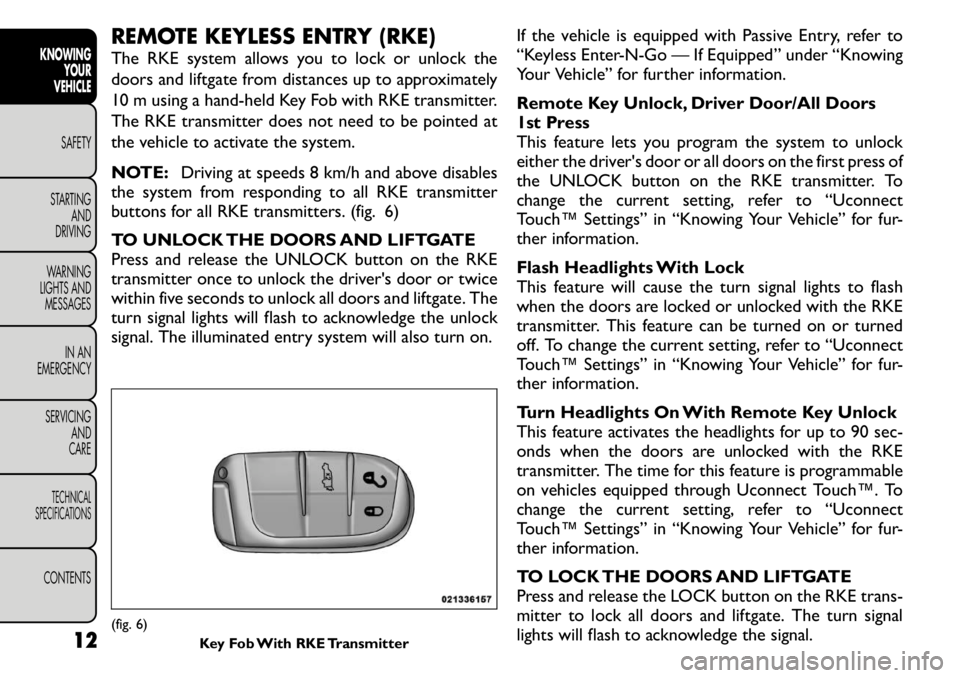
REMOTE KEYLESS ENTRY (RKE)
The RKE system allows you to lock or unlock the
doors and liftgate from distances up to approximately
10 m using a hand-held Key Fob with RKE transmitter.
The RKE transmitter does not need to be pointed at
the vehicle to activate the system.
NOTE:Driving at speeds 8 km/h and above disables
the system from responding to all RKE transmitter
buttons for all RKE transmitters. (fig. 6)
TO UNLOCK THE DOORS AND LIFTGATE
Press and release the UNLOCK button on the RKE
transmitter once to unlock the driver's door or twice
within five seconds to unlock all doors and liftgate. The
turn signal lights will flash to acknowledge the unlock
signal. The illuminated entry system will also turn on. If the vehicle is equipped with Passive Entry, refer to
“Keyless Enter-N-Go — If Equipped” under “Knowing
Your Vehicle” for further information.
Remote Key Unlock, Driver Door/All Doors
1st Press
This feature lets you program the system to unlock
either the driver's door or all doors on the first press of
the UNLOCK button on the RKE transmitter. To
change the current setting, refer to “Uconnect
Touch™ Settings” in “Knowing Your Vehicle” for fur-
ther information.
Flash Headlights With Lock
This feature will cause the turn signal lights to flash
when the doors are locked or unlocked with the RKE
transmitter. This feature can be turned on or turned
off. To change the current setting, refer to “Uconnect
Touch™ Settings” in “Knowing Your Vehicle” for fur-
ther information.
Turn Headlights On With Remote Key Unlock
This feature activates the headlights for up to 90 sec-
onds when the doors are unlocked with the RKE
transmitter. The time for this feature is programmable
on vehicles equipped through Uconnect Touch™. To
change the current setting, refer to “Uconnect
Touch™ Settings” in “Knowing Your Vehicle” for fur-
ther information.
TO LOCK THE DOORS AND LIFTGATE
Press and release the LOCK button on the RKE trans-
mitter to lock all doors and liftgate. The turn signal
lights will flash to acknowledge the signal.(fig. 6)
Key Fob With RKE Transmitter
12
KNOWING
YOUR
VEHICLE
SAFETY
STARTING AND
DRIVING
WARNING
LIGHTS AND
MESSAGES
IN AN
EMERGENCY
SERVICING AND
CARETECHNICAL
SPECIFICATIONSCONTENTS
Page 33 of 267

Display
Brightness
Press the Brightness soft-key to change this display.
When in this display you may select display brightness
with the headlights on and the headlights off. Adjust the
brightness with the + and – setting soft-keys or by
selecting any point on the scale in between the + and –
soft-keys followed by pressing the arrow back soft-key.
Mode
Press the Mode soft-key to change this display. When in
this display you may select one of the auto display
settings. To change Mode status press and release the
Day, Night or Auto soft-key followed by pressing the
arrow back soft-key.
Language
Press the Language soft-key to change this display.
When in this display you may select one of three
languages for all display nomenclature, including the
trip functions and the navigation system (if equipped).
Press the English, French (Français), Spanish (Español)
button to select the language preferred followed by
pressing the arrow back soft-key. Then, as you con-
tinue, the information will display in the selected lan-
guage.
Units
Press the Units soft-key to change this display. When in
this display you may select to have the EVIC, odometer,
and navigation system (if equipped) changed between
US and Metric units of measure. Press US or Metric
followed by pressing the arrow back soft-key. Then, asyou continue, the information will display in the se-
lected units of measure.
Voice Response
Press the Voice Response soft-key to change this dis-
play. When in this display you may change the Voice
Response Length settings. To change the Voice Re-
sponse Length press and release the Brief or Long
soft-key followed by pressing the arrow back soft-key.
Touch Screen Beep
Press the Touch Screen Beep soft-key to change this
display. When in this display you may turn on or shut off
the sound heard when a touch screen button (soft-key)
is pressed. To change the Touch Screen Beep setting
press and release the On or Off soft-key followed by
pressing the arrow back soft-key.
Fuel Saver Display
Press the Fuel Saver Display soft-key to change this
display. The “ECO” message is located in the instru-
ment cluster display, this message can be turned on or
off. To make your selection, press the Fuel Saver
Display soft-key, select On or Off followed by pressing
the arrow back soft-key. Clock
Set Time
Press the Set Time soft-key to change this display.
When in this display you may select the time display
settings. To make your selection, press the Set Time
soft-key, adjust the hours and minutes using the up and
down soft-keys, select AM or PM, select 12 hr or 24 hr
26
KNOWING YOUR
VEHICLE
SAFETY
STARTING AND
DRIVING
WARNING
LIGHTS AND
MESSAGES
IN AN
EMERGENCY
SERVICING AND
CARETECHNICAL
SPECIFICATIONSCONTENTS
Page 39 of 267
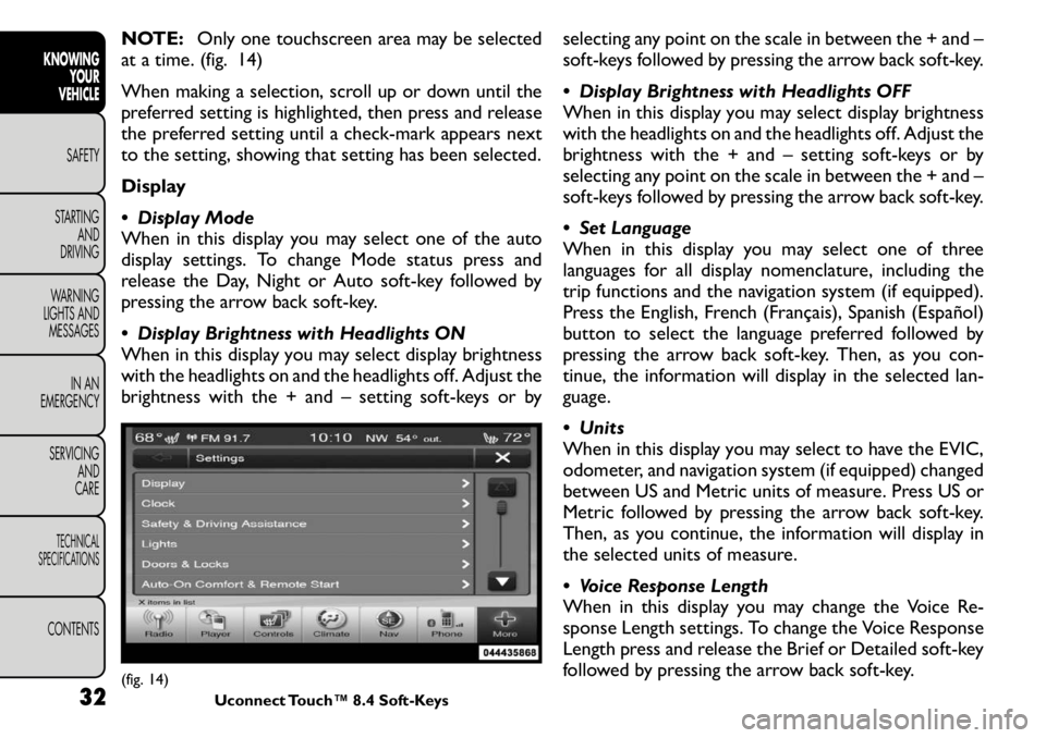
NOTE:Only one touchscreen area may be selected
at a time. (fig. 14)
When making a selection, scroll up or down until the
preferred setting is highlighted, then press and release
the preferred setting until a check-mark appears next
to the setting, showing that setting has been selected.
Display
Display Mode
When in this display you may select one of the auto
display settings. To change Mode status press and
release the Day, Night or Auto soft-key followed by
pressing the arrow back soft-key.
Display Brightness with Headlights ON
When in this display you may select display brightness
with the headlights on and the headlights off. Adjust the
brightness with the + and – setting soft-keys or by selecting any point on the scale in between the + and –
soft-keys followed by pressing the arrow back soft-key.
Display Brightness with Headlights OFF
When in this display you may select display brightness
with the headlights on and the headlights off. Adjust the
brightness with the + and – setting soft-keys or by
selecting any point on the scale in between the + and –
soft-keys followed by pressing the arrow back soft-key.
Set Language
When in this display you may select one of three
languages for all display nomenclature, including the
trip functions and the navigation system (if equipped).
Press the English, French (Français), Spanish (Español)
button to select the language preferred followed by
pressing the arrow back soft-key. Then, as you con-
tinue, the information will display in the selected lan-
guage.
Units
When in this display you may select to have the EVIC,
odometer, and navigation system (if equipped) changed
between US and Metric units of measure. Press US or
Metric followed by pressing the arrow back soft-key.
Then, as you continue, the information will display in
the selected units of measure.
Voice Response Length
When in this display you may change the Voice Re-
sponse Length settings. To change the Voice Response
Length press and release the Brief or Detailed soft-key
followed by pressing the arrow back soft-key.(fig. 14)
Uconnect Touch™ 8.4 Soft-Keys
32
KNOWING
YOUR
VEHICLE
SAFETY
STARTING AND
DRIVING
WARNING
LIGHTS AND
MESSAGES
IN AN
EMERGENCY
SERVICING AND
CARETECHNICAL
SPECIFICATIONSCONTENTS
Page 48 of 267

Touch the “Driver” or “Passenger” seat soft-
key once to select HI-level heating. Touch the
soft-key a second time to select LO-level
heating. Touch the soft-key a third time to
shut the heating elements OFF. (fig. 19)
NOTE: Once a heat setting is selected, heat will be
felt within two to five minutes.
When the HI-level setting is selected, the heater will
provide a boosted heat level during the first four
minutes of operation. Then, the heat output will drop
to the normal HI-level. If the HI-level setting is se-
lected, the system will automatically switch to LO-level
after a maximum of 60 minutes of continuous opera-
tion. At that time, the display will change from HI to
LO, indicating the change. The LO-level setting will turn
OFF automatically after a maximum of 45 minutes.
WARNING!
Persons who are unable to feel pain to
the skin because of advanced age,
chronic illness, diabetes, spinal cord injury, medi-
cation, alcohol use, exhaustion or other physical
condition must exercise care when using the seat
heater. It may cause burns even at low tempera-
tures, especially if used for long periods of time.
Do not place anything on the seat that insu-
lates against heat , such as a blanket or cushion.
This may cause the seat heater to overheat .
Sitting in a seat that has been overheated could
cause serious burns due to the increased surface
temperature of the seat .
(fig. 19) Heated Seats Soft-Key 41
KNOWING
YOURVEHICLESAFETY
STARTING ANDDRIVING
WARNING
LIGHTS AND
MESSAGES
IN AN
EMERGENCY
SERVICING AND
CARETECHNICAL
SPECIFICATIONSCONTENTS
Page 61 of 267
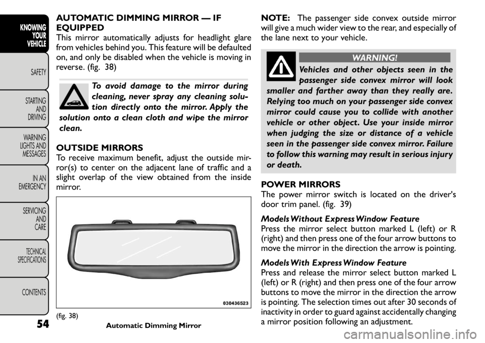
AUTOMATIC DIMMING MIRROR — IF EQUIPPED
This mirror automatically adjusts for headlight glare
from vehicles behind you. This feature will be defaulted
on, and only be disabled when the vehicle is moving in
reverse. (fig. 38)
To avoid damage to the mirror during
cleaning, never spray any cleaning solu-
tion directly onto the mirror. Apply the
solution onto a clean cloth and wipe the mirrorclean.
OUTSIDE MIRRORS
To receive maximum benefit, adjust the outside mir-
ror(s) to center on the adjacent lane of traffic and a
slight overlap of the view obtained from the inside
mirror. NOTE:
The passenger side convex outside mirror
will give a much wider view to the rear, and especially of
the lane next to your vehicle.
WARNING!
Vehicles and other objects seen in the
passenger side convex mirror will look
smaller and farther away than they really are.
Relying too much on your passenger side convex
mirror could cause you to collide with another
vehicle or other object . Use your inside mirror
when judging the size or distance of a vehicle
seen in the passenger side convex mirror. Failure
to follow this warning may result in serious injury
or death.
POWER MIRRORS
The power mirror switch is located on the driver's
door trim panel. (fig. 39)
Models Without Express Window Feature
Press the mirror select button marked L (left) or R
(right) and then press one of the four arrow buttons to
move the mirror in the direction the arrow is pointing.
Models With Express Window Feature
Press and release the mirror select button marked L
(left) or R (right) and then press one of the four arrow
buttons to move the mirror in the direction the arrow
is pointing. The selection times out after 30 seconds of
inactivity in order to guard against accidentally changing
a mirror position following an adjustment.
(fig. 38) Automatic Dimming Mirror
54
KNOWING
YOUR
VEHICLE
SAFETY
STARTING AND
DRIVING
WARNING
LIGHTS AND
MESSAGES
IN AN
EMERGENCY
SERVICING AND
CARETECHNICAL
SPECIFICATIONSCONTENTS
Page 76 of 267
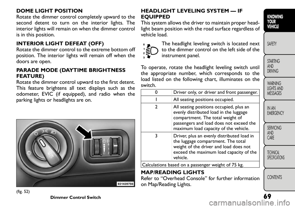
DOME LIGHT POSITION
Rotate the dimmer control completely upward to the
second detent to turn on the interior lights. The
interior lights will remain on when the dimmer control
is in this position.
INTERIOR LIGHT DEFEAT (OFF)
Rotate the dimmer control to the extreme bottom off
position. The interior lights will remain off when the
doors are open.
PARADE MODE (DAYTIME BRIGHTNESS
FEATURE)
Rotate the dimmer control upward to the first detent.
This feature brightens all text displays such as the
odometer, EVIC (if equipped), and radio when the
parking lights or headlights are on.HEADLIGHT LEVELING SYSTEM — IFEQUIPPED
This system allows the driver to maintain proper head-
light beam position with the road surface regardless of
vehicle load.
The headlight leveling switch is located next
to the dimmer control on the left side of the
instrument panel.
To operate, rotate the headlight leveling switch until
the appropriate number, which corresponds to the
load listed on the following chart, illuminates on the
switch.
0 Driver only, or driver and front passenger.
1 All seating positions occupied.
2 All seating positions occupied, plus an evenly distributed load in the luggage
compartment. The total weight of
passengers and load does not exceed the
maximum load capacity of the vehicle.
3 Driver, plus an evenly distributed load in the luggage compartment. The total
weight of the driver and load does not
exceed the maximum load capacity of the
vehicle.
Calculations based on a passenger weight of 75 kg.
MAP/READING LIGHTS
Refer to “Overhead Console” for further information
on Map/Reading Lights.
(fig. 52) Dimmer Control Switch
69KNOWING
YOURVEHICLESAFETY
STARTING ANDDRIVING
WARNING
LIGHTS AND
MESSAGES
IN AN
EMERGENCY
SERVICING AND
CARETECHNICAL
SPECIFICATIONSCONTENTS
Page 112 of 267
To avoid damage to the roof rack and
vehicle, do not exceed the maximum roof
rack load capacity of 68 kg. Always dis-
tribute loads as evenly as possible and secure the
load appropriately.
Long loads, which extend over the windshield,
such as wood panels or surfboards, or loads with
large frontal area should be secured to both the
front and rear of the vehicle.
Place a blanket or other protection between
the surface of the roof and the load.
Travel at reduced speeds and turn corners care-
fully when carrying large or heavy loads on the
roof rack. Wind forces, due to natural causes or
nearby truck traffic , can add sudden upward lift
to loads.This is especially true on large flat loads
and may result in damage to the cargo or your
vehicle.
WARNING!
Cargo must be securely tied before driv-
ing your vehicle. Improperly secured
loads can fly off the vehicle, particularly at high
speeds, resulting in personal injury or property
damage. Follow the Roof Rack Cautions when
carrying cargo on your roof rack. BRAKE SYSTEM
Your vehicle is equipped with dual hydraulic
brake systems. If either of the two hydraulic
systems loses normal capability, the remaining system
will still function. However, there will be some loss of
overall braking effectiveness. This will be evident by
increased pedal travel during application and greater
pedal force required to slow or stop the vehicle. In
addition, if the malfunction is caused by a leak in the
hydraulic system, the “Brake System Warning Light”
will turn on as the brake fluid level drops in the master
cylinder.
In the event power assist is lost for any reason (i.e.,
repeated brake applications with the engine OFF) the
brakes will still function. However, the effort required
to brake the vehicle will be much greater than that
required with the power system operating.
WARNING!
Riding the brakes can lead to brake
failure and possibly an accident . Driving
with your foot resting or riding on the brake
pedal can result in abnormally high brake tem-
peratures, excessive lining wear, and possible
brake damage.You wouldn't have your full brak-
ing capacity in an emergency.
(Continued)
105KNOWING
YOURVEHICLESAFETY
STARTING ANDDRIVING
WARNING
LIGHTS AND
MESSAGES
IN AN
EMERGENCY
SERVICING AND
CARETECHNICAL
SPECIFICATIONSCONTENTS
Page 116 of 267
WARNING!
Many factors, such as vehicle loading,
road conditions, and driving conditions,
influence the chance that wheel lift or rollover
may occur. ERM cannot prevent all wheel lift or
rollovers, especially those that involve leaving the
roadway or striking objects or other vehicles.The
capabilities of an ERM-equipped vehicle must
never be exploited in a reckless or dangerous
manner, which could jeopardize the user's safety
or the safety of others.
ELECTRONIC STABILITY CONTROL (ESC)
This system enhances directional control and stability
of the vehicle under various driving conditions. ESC
corrects for over-steering and under-steering the ve-
hicle by applying the brake of the appropriate wheel.
Engine power may also be reduced to help the vehicle
maintain the desired path.
The ESC uses sensors in the vehicle to determine the
path that the driver intends to steer the vehicle and
compares it to the actual path of the vehicle. When the
actual path does not match the intended path, the ESC
applies the brake of the appropriate wheel to assist in
counteracting the condition of over-steer or under-
steer.
• Over-steer - when the vehicle is turning more than appropriate for the steering wheel position.
• Under-steer - when the vehicle is turning less than appropriate for the steering wheel position. ESC Operating Modes
The ESC system has two available operating modes.
Full On
This is the normal operating mode for ESC. Whenever
the vehicle is started the system will be in this mode.
This mode should be used for most driving situations.
ESC should only be turned to “Partial Off ” for specific
reasons as noted. Refer to “Partial Off ” for additional
information.
Partial Off
The “ESC OFF” button is located in the switch bank
above the climate control. To enter the “Partial Off ”
mode, momentarily press the “ESC OFF” button and
the “ESC Activation/Malfunction Indicator Light” will
illuminate. To turn the ESC on again, momentarily
press the “ESC OFF” button and the “ESC Activation/
Malfunction Indicator Light” will turn off. This will
restore the normal “ESC On” mode of operation.
(fig. 100)
NOTE:
To improve the vehicle's traction when driv-
ing with snow chains, or when starting off in deep
snow, sand, or gravel, it may be desirable to switch to
the “Partial Off ” mode by momentarily pressing the
“ESC OFF” button. Once the situation requiring “Par-
tial Off ” mode is overcome, turn ESC back on by
momentarily pressing the “ESC OFF” button. This may
be done while the vehicle is in motion.
109
KNOWING
YOURVEHICLESAFETY
STARTING ANDDRIVING
WARNING
LIGHTS AND
MESSAGES
IN AN
EMERGENCY
SERVICING AND
CARETECHNICAL
SPECIFICATIONSCONTENTS
Page 119 of 267
LOOSE FUEL FILLER CAP MESSAGE
If the vehicle diagnostic system determines that the
fuel filler cap is loose, improperly installed, or damaged,
the word “gASCAP” will display in the odometer. If this
occurs, tighten the fuel filler cap until a “clicking” sound
is heard and press the TRIP ODOMETER button to
turn off the message. If the problem persists, the
message will appear the next time the vehicle is
started.
A loose, improperly installed, or damaged fuel filler cap
may also turn on the MIL.POWER STEERING
The standard power steering system will give you good
vehicle response and increased ease of maneuverability
in tight spaces. The system will provide mechanical
steering capability if power assist is lost.
If for some reason the power assist is interrupted, it
will still be possible to steer your vehicle. Under these
conditions, you will observe a substantial increase in
steering effort, especially at very low vehicle speeds
and during parking maneuvers.
NOTE:
• Increased noise levels at the end of the steering
wheel travel are considered normal and do not indicate
that there is a problem with the power steering system.
• Upon initial start-up in cold weather, the power
steering pump may make noise for a short amount of
time. This is due to the cold, thick fluid in the steering
system. This noise should be considered normal, and it
does not in any way damage the steering system.
WARNING!
Continued operation with reduced
power steering assist could pose a safety
risk to yourself and others. Service should be
obtained as soon as possible.
112
KNOWING YOUR
VEHICLE
SAFETY
STARTING AND
DRIVING
WARNING
LIGHTS AND
MESSAGES
IN AN
EMERGENCY
SERVICING AND
CARETECHNICAL
SPECIFICATIONSCONTENTS