tow FIAT FREEMONT 2012 Owner handbook (in English)
[x] Cancel search | Manufacturer: FIAT, Model Year: 2012, Model line: FREEMONT, Model: FIAT FREEMONT 2012Pages: 332, PDF Size: 5.61 MB
Page 101 of 332
automatically. This is called “Express Close”. During
Express Close operation, any movement of the switch
will stop the sunroof.
CLOSING SUNROOF — MANUAL MODE
To close the sunroof, press and hold the switch in the
forward position. Any release of the switch will stop
the movement and the sunroof will remain in a partially
closed condition until the switch is pushed and held
forward again.
PINCH PROTECT FEATURE
This feature will detect an obstruction in the opening
of the sunroof during Express Close operation. If an
obstruction is detected, the sunroof will automatically
retract. Remove the obstruction if this occurs. Next,
press the switch forward and release to Express Close.
NOTE:If three consecutive sunroof close attempts
result in Pinch Protect reversals, the fourth close at-
tempt will be a Manual Close movement with Pinch
Protect disabled.
PINCH PROTECT OVERRIDE
If a known obstruction (ice, debris, etc.) prevents
closing the sunroof, press the switch forward and hold
for two seconds after the reversal occurs. This allows
the sunroof to move toward the closed position.
NOTE: Pinch protection is disabled while the switch
is pressed. VENTING SUNROOF — EXPRESS
Press and release the “Vent” button, and the sunroof
will open to the vent position. This is called “Express
Vent”, and will occur regardless of sunroof position.
During Express Vent operation, any movement of the
switch will stop the sunroof.
SUNSHADE OPERATION
The sunshade can be opened manually. However, the
sunshade will open automatically as the sunroof opens.
NOTE:
The sunshade cannot be closed if the sunroof
is open.
WIND BUFFETING
Wind buffeting can be described as the perception of
pressure on the ears or a helicopter-type sound in the
ears. Your vehicle may exhibit wind buffeting with the
windows down, or the sunroof (for versions/markets,
where provided) is in certain open or partially open
positions. This is a normal occurrence and can be
minimized. If the buffeting occurs with the rear win-
dows open, open the front and rear windows together
to minimize the buffeting. If the buffeting occurs with
the sunroof open, adjust the sunroof opening to mini-
mize the buffeting or open any window.
SUNROOF MAINTENANCE
Use only a nonabrasive cleaner and a soft cloth to clean
the glass panel.
95
KNOWING
YOURVEHICLESAFETY
STARTING ANDDRIVING
WARNING LIGHTSAND
MESSAGES
IN AN
EMERGENCY
SERVICING AND
CARETECHNICAL
SPECIFICATIONSCONTENTS
Page 111 of 332
WIND BUFFETING
Wind buffeting can be described as the perception of
pressure on the ears or a helicopter-type sound in the
ears. Your vehicle may exhibit wind buffeting with the
windows down, or the sunroof (for versions/markets,
where provided) in certain open or partially open
positions. This is a normal occurrence and can be
minimized. If the buffeting occurs with the rear win-
dows open, then open the front and rear windows
together to minimize the buffeting. If the buffeting
occurs with the sunroof open, adjust the sunroof
opening to minimize the buffeting or open any window.LIFTGATE
The liftgate can be unlocked or locked with the Re-
mote Keyless Entry (RKE) transmitter, the Keyless
Enter-N-Go (Passive Entry) or by activating the power
door lock switch located on either front door trimpanel.
For further information on Keyless Enter-N-Go (Pas-
sive Entry), refer to “Keyless Enter-N-Go” in “Starting
And Driving”.
NOTE:
The liftgate cannot be unlocked or locked
with the manual door lock plungers on the door trim
panels or the door lock cylinder on the driver's door.
To open the unlocked liftgate, squeeze the handle and
pull the liftgate toward you. Gas props will raise and
support the liftgate in the open position. (fig. 91)
NOTE: Because the gas pressure drops with tem-
perature, it may be necessary to assist the props when
opening the liftgate in cold weather.
105
KNOWING
YOURVEHICLESAFETY
STARTING ANDDRIVING
WARNING LIGHTSAND
MESSAGES
IN AN
EMERGENCY
SERVICING AND
CARETECHNICAL
SPECIFICATIONSCONTENTS
Page 115 of 332
RETRACTABLE CARGO AREA COVER (for
versions/markets, where provided) — FIVE
PASSENGER MODELS
NOTE:The purpose of this cover is for privacy, not
to secure loads. It will not prevent cargo from shifting
or protect passengers from loose cargo.
The removable retractable cargo area cover mounts in
the cargo area behind the top of the rear seats.
The cover, when extended, covers the cargo area to
keep items out of sight. Notches in the trim panels near
the liftgate opening secure the extended cover in place.
The cover rolls away neatly inside its housing when not
in use. You can also remove the cover from the vehicle
to make more room in the cargo area.
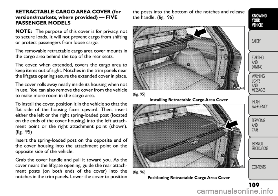
To install the cover, position it in the vehicle so that the
flat side of the housing faces upward. Then, insert
either the left or the right spring-loaded post (located
on the ends of the cover housing) into the left attach-
ment point or the right attachment point (shown).
(fig. 95)
Insert the spring-loaded post on the opposite end of
the cover housing into the attachment point on the
opposite side of the vehicle.
Grab the cover handle and pull it toward you. As the
cover nears the liftgate opening, guide the rear attach-
ment posts (on both ends of the cover) into the
notches in the trim panels. Lower the cover to position the posts into the bottom of the notches and release
the handle. (fig. 96)
(fig. 95)
Installing Retractable Cargo Area Cover(fig. 96)
Positioning Retractable Cargo Area Cover
109
KNOWING
YOURVEHICLESAFETY
STARTING ANDDRIVING
WARNING LIGHTSAND
MESSAGES
IN AN
EMERGENCY
SERVICING AND
CARETECHNICAL
SPECIFICATIONSCONTENTS
Page 126 of 332
individual wheels in an attempt to stop the trailer from
swaying.
NOTE:The TSC is disabled when the ESC system is
in the “Partial Off ” mode.
WARNING!
TSC cannot stop all trailers from
swaying. Always use caution when tow-
ing a trailer and follow the tongue weight recom-
mendations. Refer to “Trailer Towing” in “Starting
and Driving” for further information.
If TSC activates while towing a trailer, stop the
vehicle at the nearest safe location and adjust
the trailer load to eliminate the trailer sway.
Failure to follow these warnings can result in an
accident or serious personal injury. ONBOARD DIAGNOSTIC SYSTEM —
OBD II
Your vehicle is equipped with a sophisticated onboard
diagnostic system called OBD II. This system monitors
the performance of the emissions, engine, and auto-
matic transmission control systems. When these sys-
tems are operating properly, your vehicle will provide
excellent performance and fuel economy, as well as
engine emissions well within current government regu-lations.
If any of these systems require service, the OBD II
system will turn on the “Malfunction Indicator Light”
(MIL). It will also store diagnostic codes and other
information to assist your service technician in making
repairs. Although your vehicle will usually be drivable
and not need towing, see your authorized dealer for
service as soon as possible.
Prolonged driving with the MIL on
could cause further damage to the emis-
sion control system. It could also affect
fuel economy and drivability.The vehicle must be
serviced before any emissions tests can be per-
formed.
If the MIL is flashing while the engine is running,
severe catalytic converter damage and power loss
will soon occur. Immediate service is required.
120
KNOWING YOUR
VEHICLE
SAFETY
STARTING AND
DRIVING
WARNING LIGHTSAND
MESSAGES
IN AN
EMERGENCY
SERVICING AND
CARETECHNICAL
SPECIFICATIONSCONTENTS
Page 140 of 332
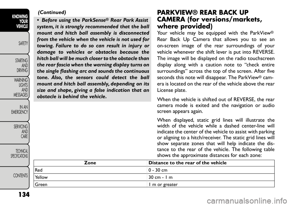
(Continued)
Before using the ParkSense
®Rear Park Assist
system, it is strongly recommended that the ball
mount and hitch ball assembly is disconnected
from the vehicle when the vehicle is not used for
towing. Failure to do so can result in injury or
damage to vehicles or obstacles because the
hitch ball will be much closer to the obstacle than
the rear fascia when the warning display turns on
the single flashing arc and sounds the continuous
tone. Also, the sensors could detect the ball
mount and hitch ball assembly, depending on its
size and shape, giving a false indication that an
obstacle is behind the vehicle. PARKVIEW® REAR BACK UP
CAMERA (for versions/markets,
where provided)
Your vehicle may be equipped with the ParkView
®
Rear Back Up Camera that allows you to see an
on-screen image of the rear surroundings of your
vehicle whenever the shift lever is put into REVERSE.
The image will be displayed on the radio touchscreen
display along with a caution note to “check entire
surroundings” across the top of the screen. After five
seconds this note will disappear. The ParkView
®cam-
era is located on the rear of the vehicle above the rear
License plate.
When the vehicle is shifted out of REVERSE, the rear
camera mode is exited and the navigation or audio
screen appears again.
When displayed, static grid lines will illustrate the
width of the vehicle while a dashed center-line will
indicate the center of the vehicle to assist with parking
or aligning to a hitch/receiver. The static grid lines will
show separate zones that will help indicate the dis-
tance to the rear of the vehicle. The following table
shows the approximate distances for each zone:
Zone Distance to the rear of the vehicle
Red 0 - 30 cm
Yellow 30 cm - 1 m
Green 1 m or greater
134
KNOWING YOUR
VEHICLE
SAFETY
STARTING AND
DRIVING
WARNING LIGHTSAND
MESSAGES
IN AN
EMERGENCY
SERVICING AND
CARETECHNICAL
SPECIFICATIONSCONTENTS
Page 151 of 332
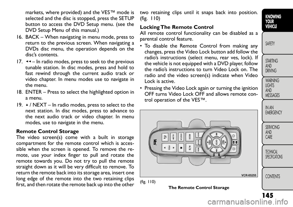
markets, where provided) and the VES™ mode is
selected and the disc is stopped, press the SETUP
button to access the DVD Setup menu. (see the
DVD Setup Menu of this manual.)
16. BACK – When navigating in menu mode, press to return to the previous screen. When navigating a
DVDs disc menu, the operation depends on the
disc’s contents.
17. ◂◂– In radio modes, press to seek to the previous
tunable station. In disc modes, press and hold to
fast rewind through the current audio track or
video chapter. In menu modes use to navigate in
the menu.
18. ENTER – Press to select the highlighted option in a menu.
19. ▴/ NEXT – In radio modes, press to select to the
next station. In disc modes, press to advance to
the next audio track or video chapter. In menu
modes, use to navigate in the menu.
Remote Control Storage
The video screen(s) come with a built in storage
compartment for the remote control which is acces-
sible when the screen is opened. To remove the re-
mote, use your index finger to pull and rotate the
remote towards you. Do not try to pull the remote
straight down as it will be very difficult to remove. To
return the remote back into its storage area, insert one
long edge of the remote into the two retaining clips
first, and then rotate the remote back up into the other two retaining clips until it snaps back into position.
(fig. 110)
Locking The Remote Control
All remote control functionality can be disabled as a
parental control feature.
• To disable the Remote Control from making any
changes, press the Video Lock button add follow the
radio’s instructions (select menu, rear ves, lock). If
the vehicle is not equipped with a DVD player, follow
the radio’s instructions to turn Video Lock on. The
radio and the video screen(s) indicate when Video
Lock is active.
• Pressing the Video Lock again or turning the ignition OFF turns Video Lock OFF and allows remote con-
trol operation of the VES™.
(fig. 110) The Remote Control Storage
145
KNOWING
YOURVEHICLESAFETY
STARTING ANDDRIVING
WARNING LIGHTSAND
MESSAGES
IN AN
EMERGENCY
SERVICING AND
CARETECHNICAL
SPECIFICATIONSCONTENTS
Page 168 of 332
5. Position the shoulder belt on your chest so that it iscomfortable and not resting on your neck. The
retractor will withdraw any slack in the belt.
6. To release the belt, push the red button on the buckle. The belt will automatically retract to its
stowed position. If necessary, slide the latch plate
down the webbing to allow the belt to retract fully.
WARNING!
A frayed or torn belt could rip apart in
an accident and leave you with no pro-
tection. Inspect the belt system periodically,
checking for cuts, frays, or loose parts. Damaged
parts must be replaced immediately. Do not dis-
assemble or modify the system. Seat belt assem-
blies must be replaced after an accident if they
have been damaged (bent retractor, torn web-
bing, etc .).
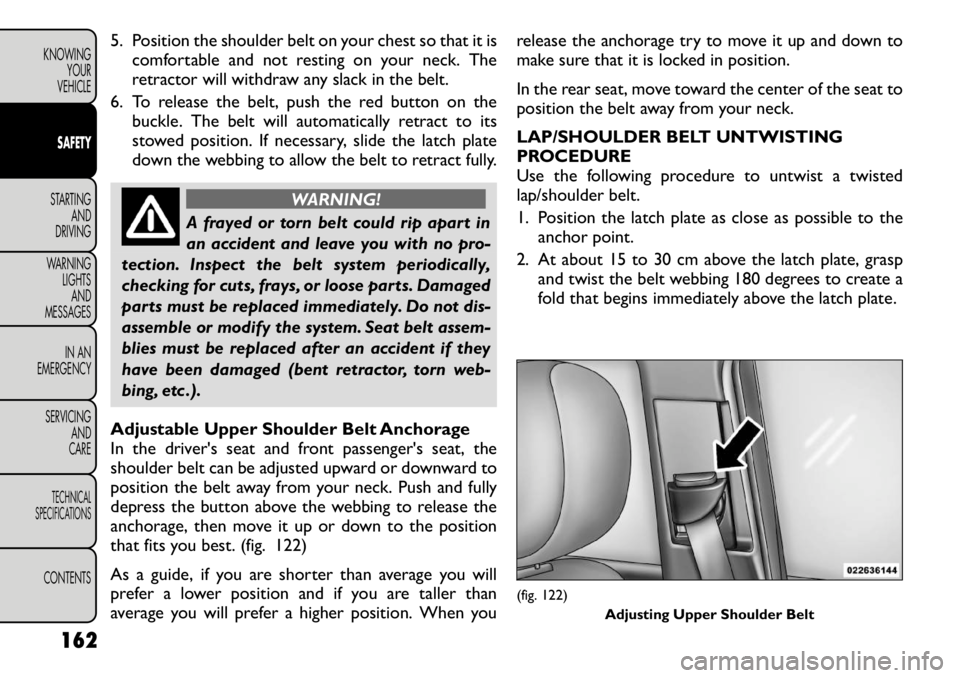
Adjustable Upper Shoulder Belt Anchorage
In the driver's seat and front passenger's seat, the
shoulder belt can be adjusted upward or downward to
position the belt away from your neck. Push and fully
depress the button above the webbing to release the
anchorage, then move it up or down to the position
that fits you best. (fig. 122)
As a guide, if you are shorter than average you will
prefer a lower position and if you are taller than
average you will prefer a higher position. When you release the anchorage try to move it up and down to
make sure that it is locked in position.
In the rear seat, move toward the center of the seat to
position the belt away from your neck.
LAP/SHOULDER BELT UNTWISTING
PROCEDURE
Use the following procedure to untwist a twisted
lap/shoulder belt.
1. Position the latch plate as close as possible to the
anchor point.
2. At about 15 to 30 cm above the latch plate, grasp and twist the belt webbing 180 degrees to create a
fold that begins immediately above the latch plate.
(fig. 122)
Adjusting Upper Shoulder Belt
162
KNOWING YOUR
VEHICLESAFETYSTARTING AND
DRIVING
WARNING LIGHTSAND
MESSAGES
IN AN
EMERGENCY
SERVICING AND
CARETECHNICAL
SPECIFICATIONSCONTENTS
Page 172 of 332
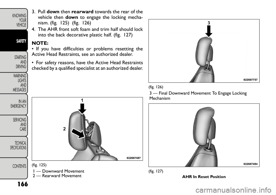
3. Pulldownthenrearward towards the rear of the
vehicle then downto engage the locking mecha-
nism. (fig. 125) (fig. 126)
4. The AHR front soft foam and trim half should lock into the back decorative plastic half. (fig. 127)
NOTE:
• If you have difficulties or problems resetting the
Active Head Restraints, see an authorized dealer.
• For safety reasons, have the Active Head Restraints
checked by a qualified specialist at an authorized dealer.(fig. 125) 1 — Downward Movement
2 — Rearward Movement
(fig. 126)3 — Final Downward Movement To Engage Locking Mechanism(fig. 127) AHR In Reset Position
166
KNOWING YOUR
VEHICLESAFETYSTARTING AND
DRIVING
WARNING LIGHTSAND
MESSAGES
IN AN
EMERGENCY
SERVICING AND
CARETECHNICAL
SPECIFICATIONSCONTENTS
Page 175 of 332
(Continued)
Drivers must be aware of pedestrians. Always
be sure to check for pedestrians, animals, other
vehicles, and obstructions.You are responsible for
safety and must continue to pay attention to
your surroundings. Failure to do so can result in
serious injury or death.
ENHANCED SEAT BELT USE REMINDER
SYSTEM (BELTALERT
®)
BeltAlert
®is a feature intended to remind the driver
and front passenger (for versions/markets, where pro-
vided with front passenger BeltAlert
®) to fasten their
seat belts. This feature is active whenever the ignition is
on. If the driver or front seat passenger is unbelted, the
Seat Belt Reminder Light will turn on and remain on
until both front seat belts are fastened. BeltAlert
®
triggers within 60 seconds of vehicle speed over
8 km/h. The reminder sequence lasts for 96 seconds or
until the respective seat belts are fastened. After the
sequence completes, the Seat Belt Reminder Light
remains illuminated until front belts are fastened. The
driver should instruct all other occupants to fasten
their seat belts. If a front seat belt is unbuckled while
traveling at speeds greater than 8 km/h, BeltAlert
®will
chime as a single notification and illuminate the Seat
Belt Reminder Light, then will proceed to the 96 sec-
ond reminder sequence. The front passenger seat BeltAlert
®is not active when
the front passenger seat is unoccupied. BeltAlert
®may
be triggered when an animal or heavy object is on the
front passenger seat or when the seat is folded flat (for
versions/markets, where provided). It is recommended
that pets be restrained in the rear seat in pet harnesses
or pet carriers that are secured by seat belts, and cargo
is properly stowed.
NOTE:
• The BeltAlert
®can be enabled or disabled by your
authorized dealer.
• The manufacturer of this vehicle does not recom-
mend deactivating the BeltAlert
®.
• If the BeltAlert
®
is deactivated, the Seat Belt Re-
minder Light will continue to illuminate as long as the
driver's seat belt is unbuckled/retracted.
SEAT BELTS AND PREGNANT WOMEN
We recommend that pregnant women use the seat
belts throughout their pregnancy. Keeping the mother
safe is the best way to keep the baby safe.
Pregnant women should wear the lap part of the belt
across the thighs and as snug across the hips as pos-
sible. Keep the belt low so that it does not come across
the abdomen. That way the strong bones of the hips
will take the force if there is an accident.
169
KNOWING
YOURVEHICLESAFETYSTARTING ANDDRIVING
WARNING LIGHTSAND
MESSAGES
IN AN
EMERGENCY
SERVICING AND
CARETECHNICAL
SPECIFICATIONSCONTENTS
Page 185 of 332
seating position, adjust the head restraint to the up-
ward position and route the tether strap between the
head restraint posts underneath the head restraint.
Then, attach the hook to the tether anchor located on
the back of the seat. Finally, tighten all three straps as
you push the child restraint rearward and downward
into the seat, removing slack in the straps according to
the child restraint manufacturer's instructions.
NOTE:
• Ensure that the tether strap does not slip into the
opening between the seatbacks as you remove slack in
the strap.
• When using the ISOFIX attaching system to install a
child restraint, please ensure that all seat belts not
being used for occupant restraints are stowed and out
of reach of children. Remind all children in the vehicle
that the seat belts are not toys and that they should not
play with them. In addition, never leave unattended
children in the vehicle.
WARNING!
Improper installation of a child restraint
to the ISOFIX anchorages can lead to
failure of an infant or child restraint . The child
could be badly injured or killed. Follow the manu-
facturer's directions exactly when installing an
infant or child restraint . Installing Child Restraints Using The Vehicle
Seat Belt
The seat belts in the passenger seating positions are
equipped with an Automatic Locking Retractor (ALR)
or a cinching latch plate to secure a Child Restraint
System (CRS). These types of seat belts are designed to
keep the lap portion of the seat belt tight around the
child restraint so that it is not necessary to use a
locking clip. The ALR will make a ratcheting noise if you
extract the entire belt from the retractor and then
allow the belt to retract into the retractor. For addi-
tional information on ALR, refer to “Automatic Locking
Mode” description under “Seat Belts in Passenger Seat-
ing Positions” section. The chart below defines the
seating positions with an Automatic Locking Retractor
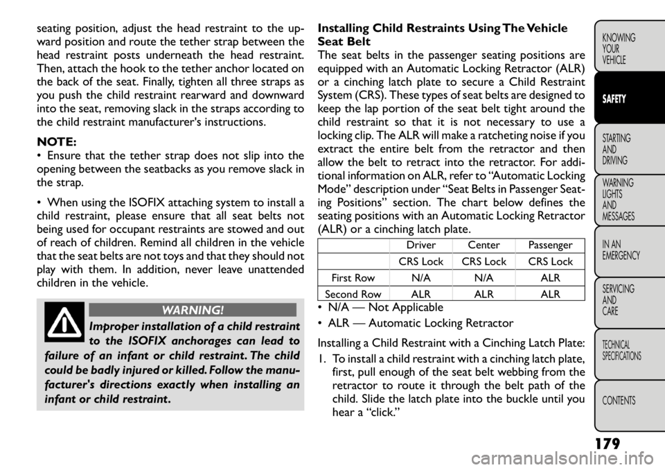
(ALR) or a cinching latch plate.
Driver Center Passenger
CRS Lock CRS Lock CRS Lock
First Row N/A N/A ALR
Second Row ALR ALR ALR
• N/A — Not Applicable
• ALR — Automatic Locking Retractor
Installing a Child Restraint with a Cinching Latch Plate:
1. To install a child restraint with a cinching latch plate,
first, pull enough of the seat belt webbing from the
retractor to route it through the belt path of the
child. Slide the latch plate into the buckle until you
hear a “click.”
179
KNOWING
YOURVEHICLESAFETYSTARTING ANDDRIVING
WARNING LIGHTSAND
MESSAGES
IN AN
EMERGENCY
SERVICING AND
CARETECHNICAL
SPECIFICATIONSCONTENTS