stop start FIAT FREEMONT 2012 Owner handbook (in English)
[x] Cancel search | Manufacturer: FIAT, Model Year: 2012, Model line: FREEMONT, Model: FIAT FREEMONT 2012Pages: 332, PDF Size: 5.61 MB
Page 125 of 332
WARNING!
When in “Partial Off ” mode, the TCS
functionality of ESC, (except for the lim-
ited slip feature described in the TCS section), has
been disabled and the “ESC Off Indicator Light”
will be illuminated. All other stability features of
ESC function normally. When in “Partial Off ”
mode, the engine power reduction feature of TCS
is disabled, and the enhanced vehicle stability
offered by the ESC system is reduced.
ESC ACTIVATION/MALFUNCTION
INDICATOR LIGHT AND ESC OFF
INDICATOR LIGHT The “ESC Activation/Malfunction Indicator
Light” in the instrument cluster will come on
when the ignition switch is turned to the ON
position. It should go out with the engine
running. If the “ESC Activation/Malfunction Indicator
Light” comes on continuously with the engine running,
a malfunction has been detected in the ESC system. If
this light remains on after several ignition cycles, and
the vehicle has been driven several kilometers at
speeds greater than 48 km/h, see your authorized
dealer as soon as possible to have the problem diag-
nosed and corrected.
The “ESC Activation/Malfunction Indicator Light” (lo-
cated in the instrument cluster) starts to flash as soon as the tires lose traction and the ESC system becomes
active. The “ESC Activation/Malfunction Indicator
Light” also flashes when TCS is active. If the “ESC
Activation/Malfunction Indicator Light” begins to flash
during acceleration, ease up on the accelerator and
apply as little throttle as possible. Be sure to adapt your
speed and driving to the prevailing road conditions.
NOTE:
• The “ESC Activation/Malfunction Indicator Light”
and the “ESC OFF Indicator Light” come on momen-
tarily each time the ignition switch is turned ON.
• Each time the ignition is turned ON, the ESC system
will be ON even if it was turned off previously.
• The ESC system will make buzzing or clicking sounds
when it is active. This is normal; the sounds will stop
when ESC becomes inactive following the maneuver
that caused the ESC activation.
The “ESC OFF Indicator Light” indicates the
Electronic Stability Control (ESC) is off.
TRAILER SWAY CONTROL (TSC)
TSC uses sensors in the vehicle to recognize an exces-
sively swaying trailer. TSC activates automatically once
the excessively swaying trailer is recognized. When
TSC is functioning, the “ESC Activation/Malfunction
Indicator Light” will flash, the engine power will be
reduced, and you will feel the brake being applied to
119KNOWING
YOURVEHICLESAFETY
STARTING ANDDRIVING
WARNING LIGHTSAND
MESSAGES
IN AN
EMERGENCY
SERVICING AND
CARETECHNICAL
SPECIFICATIONSCONTENTS
Page 126 of 332
individual wheels in an attempt to stop the trailer from
swaying.
NOTE:The TSC is disabled when the ESC system is
in the “Partial Off ” mode.
WARNING!
TSC cannot stop all trailers from
swaying. Always use caution when tow-
ing a trailer and follow the tongue weight recom-
mendations. Refer to “Trailer Towing” in “Starting
and Driving” for further information.
If TSC activates while towing a trailer, stop the
vehicle at the nearest safe location and adjust
the trailer load to eliminate the trailer sway.
Failure to follow these warnings can result in an
accident or serious personal injury. ONBOARD DIAGNOSTIC SYSTEM —
OBD II
Your vehicle is equipped with a sophisticated onboard
diagnostic system called OBD II. This system monitors
the performance of the emissions, engine, and auto-
matic transmission control systems. When these sys-
tems are operating properly, your vehicle will provide
excellent performance and fuel economy, as well as
engine emissions well within current government regu-lations.
If any of these systems require service, the OBD II
system will turn on the “Malfunction Indicator Light”
(MIL). It will also store diagnostic codes and other
information to assist your service technician in making
repairs. Although your vehicle will usually be drivable
and not need towing, see your authorized dealer for
service as soon as possible.
Prolonged driving with the MIL on
could cause further damage to the emis-
sion control system. It could also affect
fuel economy and drivability.The vehicle must be
serviced before any emissions tests can be per-
formed.
If the MIL is flashing while the engine is running,
severe catalytic converter damage and power loss
will soon occur. Immediate service is required.
120
KNOWING YOUR
VEHICLE
SAFETY
STARTING AND
DRIVING
WARNING LIGHTSAND
MESSAGES
IN AN
EMERGENCY
SERVICING AND
CARETECHNICAL
SPECIFICATIONSCONTENTS
Page 130 of 332

NOTE:
• The TPMS is not intended to replace normal tire care
and maintenance, or to provide warning of a tire failure
or condition.
• The TPMS should not be used as a tire pressure
gauge while adjusting your tire pressure.
• Driving on a significantly under-inflated tire causes
the tire to overheat and can lead to tire failure. Under-
inflation also reduces fuel efficiency and tire tread life,
and may affect the vehicle’s handling and stopping
ability.
• The TPMS is not a substitute for proper tire mainte-
nance, and it is the driver’s responsibility to maintain
correct tire pressure using an accurate tire pressure
gauge, even if under-inflation has not reached the level
to trigger illumination of the Tire Pressure Monitoring
Telltale Light.
• Seasonal temperature changes will affect tire pres-
sure, and the TPMS will monitor the actual tire pres-
sure in the tire.
BASE SYSTEM
The Tire Pressure Monitor System (TPMS) uses wire-
less technology with wheel rim mounted electronic
sensors to monitor tire pressure levels. Sensors,
mounted to each wheel as part of the valve stem,
transmit tire pressure readings to the receiver module.NOTE:
It is particularly important for you to check
the tire pressure in all of the tires on your vehicle
monthly and to maintain the proper pressure.
The TPMS consists of the following components:
• Receiver Module
• Four Tire Pressure Monitoring Sensors
• Tire Pressure Monitoring Telltale Light
Tire Pressure Monitoring Low Pressure
Warnings
The Tire Pressure Monitoring Telltale Light will
illuminate in the instrument cluster and a chime
will sound when tire pressure is low in one or
more of the four active road tires. Should this occur,
you should stop as soon as possible, check the inflation
pressure of each tire on your vehicle, and inflate each
tire to the vehicle’s recommended cold placard pres-
sure value. Once the system receives the updated tire
pressures, the system will automatically update and the
Tire Pressure Monitoring Telltale Light will turn off.
The vehicle may need to be driven for up to 20 minutes
above 25 km/h in order for the TPMS to receive this
information.
Check TPMS Warning
When a system fault is detected, the Tire Pressure
Monitoring Telltale Light will flash on and off for 75 sec-
onds and then remain on solid. The system fault will
also sound a chime. If the ignition switch is cycled, this
sequence will repeat, providing the system fault still
124
KNOWING YOUR
VEHICLE
SAFETY
STARTING AND
DRIVING
WARNING LIGHTSAND
MESSAGES
IN AN
EMERGENCY
SERVICING AND
CARETECHNICAL
SPECIFICATIONSCONTENTS
Page 132 of 332
PREMIUM SYSTEM (for versions/markets,
where provided)
The Tire Pressure Monitor System (TPMS) uses wire-
less technology with wheel rim mounted electronic
sensors to monitor tire pressure levels. Sensors,
mounted to each wheel as part of the valve stem,
transmit tire pressure readings to the receiver module.
NOTE:It is particularly important for you to check
the tire pressure in all of the tires on your vehicle
monthly and to maintain the proper pressure.
The TPMS consists of the following components:
• Receiver module
• Four Tire Pressure Monitoring Sensors
• Three Trigger modules (mounted in three of the four wheel-wells)
• Various Tire Pressure Monitoring System messages, which display in the Electronic Vehicle Information
Center (EVIC)
• Tire Pressure Monitoring Telltale Light
Tire Pressure Monitoring Low Pressure
Warnings
The Tire Pressure Monitoring Telltale Light will
illuminate in the instrument cluster and a chime
will sound when tire pressure is low in one or
more of the four active road tires. In addition, the
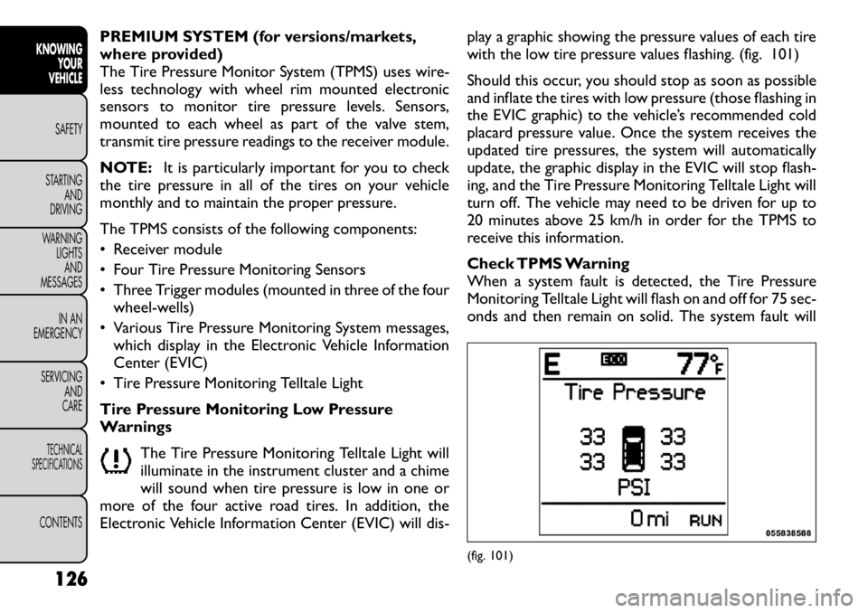
Electronic Vehicle Information Center (EVIC) will dis- play a graphic showing the pressure values of each tire
with the low tire pressure values flashing. (fig. 101)
Should this occur, you should stop as soon as possible
and inflate the tires with low pressure (those flashing in
the EVIC graphic) to the vehicle’s recommended cold
placard pressure value. Once the system receives the
updated tire pressures, the system will automatically
update, the graphic display in the EVIC will stop flash-
ing, and the Tire Pressure Monitoring Telltale Light will
turn off. The vehicle may need to be driven for up to
20 minutes above 25 km/h in order for the TPMS to
receive this information.
Check TPMS Warning
When a system fault is detected, the Tire Pressure
Monitoring Telltale Light will flash on and off for 75 sec-
onds and then remain on solid. The system fault will
(fig. 101)
126
KNOWING YOUR
VEHICLE
SAFETY
STARTING AND
DRIVING
WARNING LIGHTSAND
MESSAGES
IN AN
EMERGENCY
SERVICING AND
CARETECHNICAL
SPECIFICATIONSCONTENTS
Page 139 of 332
• When you move the shift lever to the REVERSE
position and ParkSense
®is turned off, the EVIC will
display the “PARK ASSIST OFF” message for as long as
the vehicle is in REVERSE.
• Clean the ParkSense
®sensors regularly, taking care
not to scratch or damage them. The sensors must not
be covered with ice, snow, slush, mud, dirt or debris.
Failure to do so can result in the system not working
properly. The ParkSense®system might not detect an
obstacle behind the fascia/bumper, or it could provide a
false indication that an obstacle is behind the fascia/
bumper.
• Objects such as bicycle carriers, trailer hitches, etc.,
must not be placed within 30 cm from the rear fascia/
bumper while driving the vehicle. Failure to do so can
result in the system misinterpreting a close object as a
sensor problem, causing the “SERVICE PARK ASSIST
SYSTEM” message to be displayed in the EVIC.
ParkSense
®is only a parking aid and it
is unable to recognize every obstacle,
including small obstacles. Parking curbs
might be temporarily detected or not detected at
all. Obstacles located above or below the sensors
will not be detected when they are in close prox-
imity.
The vehicle must be driven slowly when using
ParkSense
®
in order to be able to stop in time
when an obstacle is detected. It is recommended
that the driver looks over his/her shoulder when
using ParkSense
®.
WARNING!
Drivers must be careful when backing
up even when using the ParkSense
®
Rear Park Assist system. Always check carefully
behind your vehicle, look behind you, and be sure
to check for pedestrians, animals, other vehicles,
obstructions, and blind spots before backing up.
You are responsible for safety and must continue
to pay attention to your surroundings. Failure to
do so can result in serious injury or death.
(Continued)
133
KNOWING
YOURVEHICLESAFETY
STARTING ANDDRIVING
WARNING LIGHTSAND
MESSAGES
IN AN
EMERGENCY
SERVICING AND
CARETECHNICAL
SPECIFICATIONSCONTENTS
Page 141 of 332
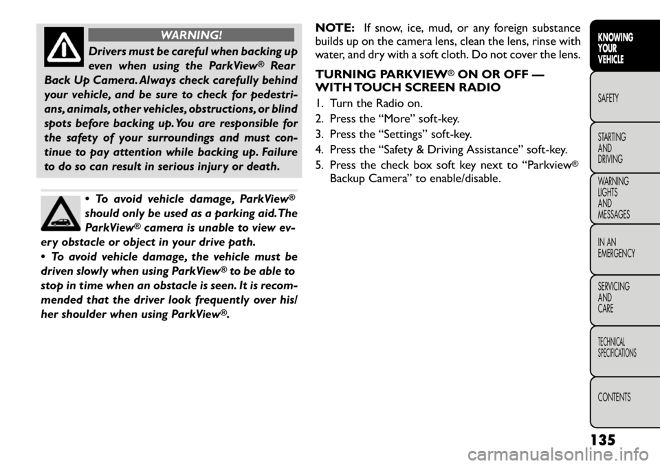
WARNING!
Drivers must be careful when backing up
even when using the ParkView
®
Rear
Back Up Camera. Always check carefully behind
your vehicle, and be sure to check for pedestri-
ans, animals, other vehicles, obstructions, or blind
spots before backing up. You are responsible for
the safety of your surroundings and must con-
tinue to pay attention while backing up. Failure
to do so can result in serious injury or death.
To avoid vehicle damage, ParkView
®
should only be used as a parking aid.The
ParkView
®camera is unable to view ev-
ery obstacle or object in your drive path.
To avoid vehicle damage, the vehicle must be
driven slowly when using ParkView
®to be able to
stop in time when an obstacle is seen. It is recom-
mended that the driver look frequently over his/
her shoulder when using ParkView®. NOTE:
If snow, ice, mud, or any foreign substance
builds up on the camera lens, clean the lens, rinse with
water, and dry with a soft cloth. Do not cover the lens.
TURNING PARKVIEW
®ON OR OFF —
WITH TOUCH SCREEN RADIO
1. Turn the Radio on.
2. Press the “More” soft-key.
3. Press the “Settings” soft-key.
4. Press the “Safety & Driving Assistance” soft-key.
5. Press the check box soft key next to “Parkview
®
Backup Camera” to enable/disable.
135
KNOWING
YOURVEHICLESAFETY
STARTING ANDDRIVING
WARNING LIGHTSAND
MESSAGES
IN AN
EMERGENCY
SERVICING AND
CARETECHNICAL
SPECIFICATIONSCONTENTS
Page 148 of 332
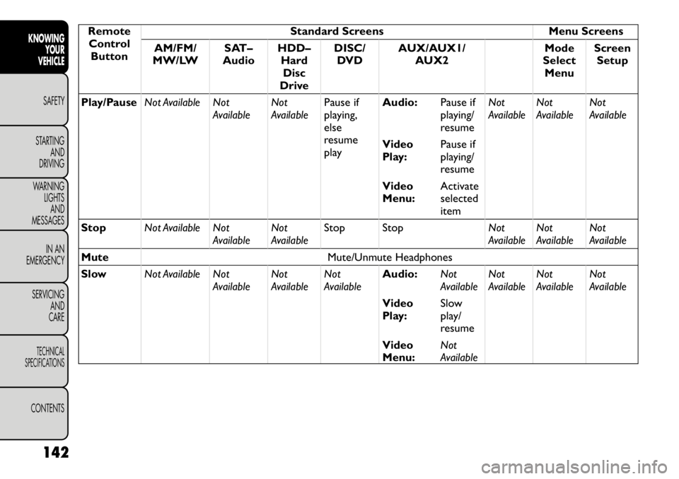
RemoteControl Button Standard Screens Menu Screens
AM/FM/
MW/LW SAT–
Audio HDD–
HardDisc
Drive DISC/
DVD AUX/AUX1/
AUX2 Mode
Select Menu Screen
Setup
Play/Pause Not Available Not
AvailableNot
AvailablePause if
playing,else
resume
play Audio:
Pause if
playing/
resumeNot
Available
Not
Available Not
Available
Video
Play: Pause if
playing/
resume
Video
Menu: Activate
selected
item
Stop Not Available Not
AvailableNot
AvailableStop Stop
Not
AvailableNot
Available Not
Available
Mute Mute/Unmute Headphones
Slow Not Available Not
AvailableNot
AvailableNot
Available Audio:
Not
AvailableNot
AvailableNot
Available Not
Available
Video
Play: Slow
play/
resume
Video
Menu: Not
Available
142
KNOWING YOUR
VEHICLE
SAFETY
STARTING AND
DRIVING
WARNING LIGHTSAND
MESSAGES
IN AN
EMERGENCY
SERVICING AND
CARETECHNICAL
SPECIFICATIONSCONTENTS
Page 150 of 332
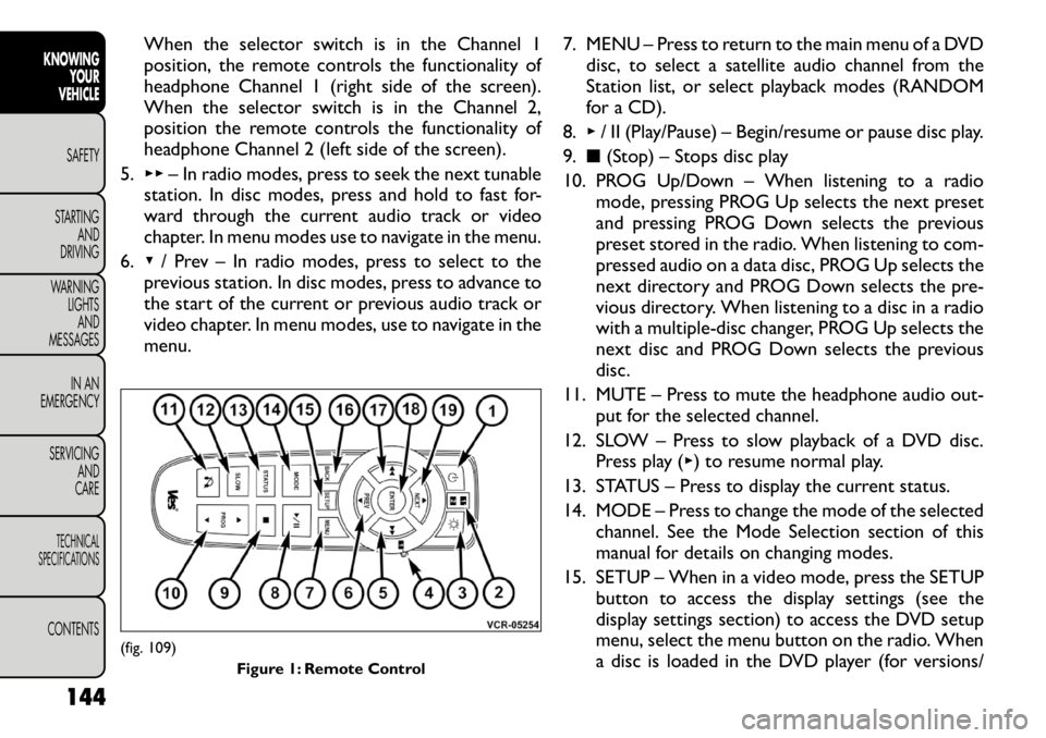
When the selector switch is in the Channel 1
position, the remote controls the functionality of
headphone Channel 1 (right side of the screen).
When the selector switch is in the Channel 2,
position the remote controls the functionality of
headphone Channel 2 (left side of the screen).
5. ▸▸ – In radio modes, press to seek the next tunable
station. In disc modes, press and hold to fast for-
ward through the current audio track or video
chapter. In menu modes use to navigate in the menu.
6. ▾/ Prev – In radio modes, press to select to the
previous station. In disc modes, press to advance to
the start of the current or previous audio track or
video chapter. In menu modes, use to navigate in the
menu. 7. MENU – Press to return to the main menu of a DVD
disc, to select a satellite audio channel from the
Station list, or select playback modes (RANDOM
for a CD).
8. ▸/ II (Play/Pause) – Begin/resume or pause disc play.
9. ■(Stop) – Stops disc play
10. PROG Up/Down – When listening to a radio mode, pressing PROG Up selects the next preset
and pressing PROG Down selects the previous
preset stored in the radio. When listening to com-
pressed audio on a data disc, PROG Up selects the
next directory and PROG Down selects the pre-
vious directory. When listening to a disc in a radio
with a multiple-disc changer, PROG Up selects the
next disc and PROG Down selects the previous
disc.
11. MUTE – Press to mute the headphone audio out- put for the selected channel.
12. SLOW – Press to slow playback of a DVD disc. Press play ( ▸) to resume normal play.
13. STATUS – Press to display the current status.
14. MODE – Press to change the mode of the selected channel. See the Mode Selection section of this
manual for details on changing modes.
15. SETUP – When in a video mode, press the SETUP button to access the display settings (see the
display settings section) to access the DVD setup
menu, select the menu button on the radio. When
a disc is loaded in the DVD player (for versions/
(fig. 109)
Figure 1: Remote Control
144
KNOWING YOUR
VEHICLE
SAFETY
STARTING AND
DRIVING
WARNING LIGHTSAND
MESSAGES
IN AN
EMERGENCY
SERVICING AND
CARETECHNICAL
SPECIFICATIONSCONTENTS
Page 151 of 332
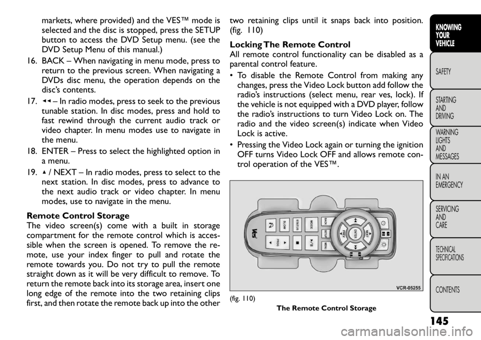
markets, where provided) and the VES™ mode is
selected and the disc is stopped, press the SETUP
button to access the DVD Setup menu. (see the
DVD Setup Menu of this manual.)
16. BACK – When navigating in menu mode, press to return to the previous screen. When navigating a
DVDs disc menu, the operation depends on the
disc’s contents.
17. ◂◂– In radio modes, press to seek to the previous
tunable station. In disc modes, press and hold to
fast rewind through the current audio track or
video chapter. In menu modes use to navigate in
the menu.
18. ENTER – Press to select the highlighted option in a menu.
19. ▴/ NEXT – In radio modes, press to select to the
next station. In disc modes, press to advance to
the next audio track or video chapter. In menu
modes, use to navigate in the menu.
Remote Control Storage
The video screen(s) come with a built in storage
compartment for the remote control which is acces-
sible when the screen is opened. To remove the re-
mote, use your index finger to pull and rotate the
remote towards you. Do not try to pull the remote
straight down as it will be very difficult to remove. To
return the remote back into its storage area, insert one
long edge of the remote into the two retaining clips
first, and then rotate the remote back up into the other two retaining clips until it snaps back into position.
(fig. 110)
Locking The Remote Control
All remote control functionality can be disabled as a
parental control feature.
• To disable the Remote Control from making any
changes, press the Video Lock button add follow the
radio’s instructions (select menu, rear ves, lock). If
the vehicle is not equipped with a DVD player, follow
the radio’s instructions to turn Video Lock on. The
radio and the video screen(s) indicate when Video
Lock is active.
• Pressing the Video Lock again or turning the ignition OFF turns Video Lock OFF and allows remote con-
trol operation of the VES™.
(fig. 110) The Remote Control Storage
145
KNOWING
YOURVEHICLESAFETY
STARTING ANDDRIVING
WARNING LIGHTSAND
MESSAGES
IN AN
EMERGENCY
SERVICING AND
CARETECHNICAL
SPECIFICATIONSCONTENTS
Page 159 of 332

Disc Features control the remote DVD player's (for
versions/markets, where provided) settings of DVD
being watched in the remote player.
Listening To Audio With The Screen Closed
To listen to only audio portion of the channel with the
screen closed:
• Set the audio to the desired source and channel.
• Close the video screen.
• To change the current audio mode, press the remotecontrol’s MODE button. This will automatically se-
lect the next available audio mode without using the
Mode Select menu.
• When the screen is reopened, the video screen will automatically turn back on and show the appropriate
display menu or media.
If the screen is closed and there is no audio heard,
verify that the headphones are turned on (the ON
indicator is illuminated) and the headphone selector
switch is on the desired channel. If the headphones are
turned on, press the remote control’s power button to
turn audio on. If audio is still not heard, check that fully
charged batteries are installed in the headphones. Why Does The Screen Mode Change
Automatically?
In order to make the operation of the VES™ simple
and with the least amount of driver distraction, specific
events will cause the screen(s) to automatically switch
to DVD mode. These events are:
• Loading a disc in the DVD player (if so equipped),
• Pressing the PLAY button on the DVD player face-
plate when the disc is stopped or paused, or
• AM/FM band selection via Radio.
If your vehicle is not equipped with the separate DVD
player, the following events in the Radio will cause the
screen(s) to automatically switch to Radio Disc mode.
• Loading a disc in the radio CD/DVD player
• AM/FM band selection via Radio
Auxiliary Inputs
For each video screen there is an auxiliary (Aux jack)
device input which is used to connect external audio/
video sources to the VES™. Examples of devices that
can be connected to the Aux inputs include portable
music players, video cameras, VCR’s, game systems,
and other devices with audio and/or video outputs.
The Aux jacks are typically located on the back of the
center console or on one of the vehicles side panels in
the rear occupant area.
153
KNOWING
YOURVEHICLESAFETY
STARTING ANDDRIVING
WARNING LIGHTSAND
MESSAGES
IN AN
EMERGENCY
SERVICING AND
CARETECHNICAL
SPECIFICATIONSCONTENTS