wheel FIAT FREEMONT 2012 Owner handbook (in English)
[x] Cancel search | Manufacturer: FIAT, Model Year: 2012, Model line: FREEMONT, Model: FIAT FREEMONT 2012Pages: 332, PDF Size: 5.61 MB
Page 24 of 332

SECURITY SYSTEM MANUAL OVERRIDE
The system will not arm if you lock the doors using the
manual door lock plunger.STEERING WHEEL LOCK (for
versions/markets, where
provided)
Your vehicle may be equipped with a passive electronic
steering wheel lock. This lock prevents steering the
vehicle without the ignition key. The steering wheel
lock has six positions (one every 60 degrees). If the
steering wheel is moved to one of these six position
with the key in the off positions, the steering wheel will
lock.
TO MANUALLY LOCK THE STEERING WHEEL
With the engine running, rotate the steering wheel
one-half revolution, turn off the engine and remove the
key. Turn the steering wheel slightly in either direction
until the lock engages.
TO RELEASE THE STEERING WHEEL LOCK
Cycle the ignition and start the engine.
NOTE:
If you turned the wheel to the right to engage
the lock, you must turn the wheel slightly to the right
to disengage it. If you turned the wheel to the left to
engage the lock, turn the wheel slightly to the left to
disengage it.
18
KNOWING YOUR
VEHICLE
SAFETY
STARTING AND
DRIVING
WARNING LIGHTSAND
MESSAGES
IN AN
EMERGENCY
SERVICING AND
CARETECHNICAL
SPECIFICATIONSCONTENTS
Page 25 of 332
ELECTRONIC VEHICLE
INFORMATION CENTER (EVIC)
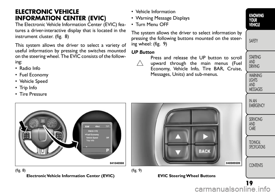
The Electronic Vehicle Information Center (EVIC) fea-
tures a driver-interactive display that is located in the
instrument cluster. (fig. 8)
This system allows the driver to select a variety of
useful information by pressing the switches mounted
on the steering wheel. The EVIC consists of the follow-ing:
• Radio Info
• Fuel Economy
• Vehicle Speed
• Trip Info
• Tire Pressure• Vehicle Information
• Warning Message Displays
• Turn Menu OFF
The system allows the driver to select information by
pressing the following buttons mounted on the steer-
ing wheel: (fig. 9)
UP Button
Press and release the UP button to scroll
upward through the main menus (Fuel
Economy, Vehicle Info, Tire BAR, Cruise,
Messages, Units) and sub-menus.(fig. 8)
Electronic Vehicle Information Center (EVIC)
(fig. 9) EVIC Steering Wheel Buttons
19KNOWING
YOURVEHICLESAFETY
STARTING ANDDRIVING
WARNING LIGHTSAND
MESSAGES
IN AN
EMERGENCY
SERVICING AND
CARETECHNICAL
SPECIFICATIONSCONTENTS
Page 32 of 332

MESSAGES
In the Main Menu, press and release the UP or DOWN
button until “Messages: XX” displays highlighted in the
EVIC. If there is more than one message, pressing the
SELECT button will display a stored warning message.
Press and release the UP and DOWN buttons if there
is more than one message to step through the remain-
ing stored messages. If there are no message, pressing
the SELECT button will do nothing.
TURN MENU OFF
Select from Main Menu using the DOWN button.
Pressing the SELECT button blanks the menu display.
Pressing any one of the four steering wheel buttons
brings the menu back.Uconnect Touch™ SETTINGS
HARD-KEYS
Hard-Keys are located on the left and right side of the
Uconnect Touch™ 4.3 screen. In addition, there is a
Scroll/Enter control knob located on the right side of
the Climate Controls in the center of the instrument
panel. Turn the control knob to scroll through menus
and change settings (i.e., 30, 60, 90), press the center of
the control knob one or more times to select or
change a setting (i.e., ON, OFF).
SOFT-KEYS
Soft-Keys are accessible on the Uconnect Touch™
display.
CUSTOMER PROGRAMMABLE FEATURES
— Uconnect Touch™ SYSTEM 4.3 SETTINGS
In this mode the Uconnect Touch™ system allows you
to access programmable features that may be equipped
such as Display, Clock, Safety/Assistance, Lights, Doors
& Locks, Heated Seats, Engine Off Operation, Com-
pass Settings, Audio and Phone/Bluetooth settings
through hard-keys and soft-keys.
NOTE:
Only one touchscreen area may be selected
at a time.
Press the "Settings" hard-key to access the Settings
screen, use the Page Up/Down soft-keys to scroll
through the following settings. Touch the desired set-
ting soft key to change the setting using the description
26
KNOWING YOUR
VEHICLE
SAFETY
STARTING AND
DRIVING
WARNING LIGHTSAND
MESSAGES
IN AN
EMERGENCY
SERVICING AND
CARETECHNICAL
SPECIFICATIONSCONTENTS
Page 61 of 332
WARNING!
Be certain that the seatback is locked
securely into position. Otherwise, the
seat will not provide the proper stability for
passengers. An improperly latched seat could
cause serious injury.
Do not allow a passenger to sit in a third row
seat without having the head restraint unfolded
and locked in place. Failure to follow this warning
may result in personal injury to the passenger in
the event of a collision.
Do not allow a passenger to sit in a third row
seat with the second row seatback(s) folded flat .
In a collision, the passenger could slide under-
neath the seat belt and be seriously or even
fatally injured. TILT/TELESCOPING STEERING
COLUMN
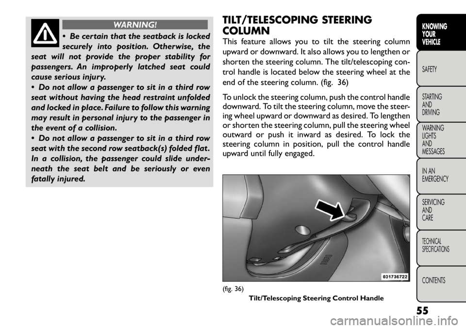
This feature allows you to tilt the steering column
upward or downward. It also allows you to lengthen or
shorten the steering column. The tilt/telescoping con-
trol handle is located below the steering wheel at the
end of the steering column. (fig. 36)
To unlock the steering column, push the control handle
downward. To tilt the steering column, move the steer-
ing wheel upward or downward as desired. To lengthen
or shorten the steering column, pull the steering wheel
outward or push it inward as desired. To lock the
steering column in position, pull the control handle
upward until fully engaged.
(fig. 36)
Tilt/Telescoping Steering Control Handle
55
KNOWING
YOURVEHICLESAFETY
STARTING ANDDRIVING
WARNING LIGHTSAND
MESSAGES
IN AN
EMERGENCY
SERVICING AND
CARETECHNICAL
SPECIFICATIONSCONTENTS
Page 69 of 332

8. Climate Control OFF Button
Press and release this button to turn the Climate
Control ON/OFF.
9. AUTO Operation Button (for versions/markets,
where provided)
Automatically controls the interior cabin temperature
by adjusting airflow distribution and amount. Perform-
ing this function will cause the ATC to switch between
manual mode and automatic modes. Refer to “Auto-
matic Operation” for more information.
10. Driver Temperature Control Down Button
Provides the driver with independent temperature
control. Push the button for cooler temperature set-tings.
NOTE:In Sync mode, this button will also automati-
cally adjust the passenger and rear temperature setting
at the same time.
11. Driver Temperature Control Up Button
Provides the driver with independent temperature
control. Push the button for warmer temperaturesettings.
NOTE: In Sync mode, this button will also automati-
cally adjust the passenger and rear temperature setting
at the same time.
12. Modes
The airflow distribution mode can be adjusted so air
comes from the instrument panel outlets, floor outlets, demist outlets and defrost outlets. The Mode settings
are as follows:
Panel Mode
Air comes from the outlets in the instrument
panel. Each of these outlets can be individually
adjusted to direct the flow of air. The air vanes of the
center outlets and outboard outlets can be moved up
and down or side-to-side to regulate airflow direction.
There is a shut off wheel, located below the air vanes,
to shut off or adjust the amount of airflow from theseoutlets. Bi-Level Mode
Air comes from the instrument panel outlets and
floor outlets. A slight amount of air is directed
through the defrost and side window demister outlets.
NOTE: BI-LEVEL mode is designed under comfort
conditions to provide cooler air out of the panel
outlets and warmer air from the floor outlets. Floor Mode
Air comes from the floor outlets. A slight amount
of air is directed through the defrost and side
window demister outlets. Mix Mode
Air comes from the floor, defrost and side win-
dow demist outlets. This mode works best in
cold or snowy conditions.
63KNOWING
YOURVEHICLESAFETY
STARTING ANDDRIVING
WARNING LIGHTSAND
MESSAGES
IN AN
EMERGENCY
SERVICING AND
CARETECHNICAL
SPECIFICATIONSCONTENTS
Page 87 of 332
ELECTRONIC SPEED CONTROL (for
versions/markets, where
provided)
When engaged, the Electronic Speed Control takes
over accelerator operations at speeds greater than
40 km/h.
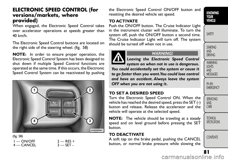
The Electronic Speed Control buttons are located on
the right side of the steering wheel. (fig. 58)
NOTE:In order to ensure proper operation, the
Electronic Speed Control System has been designed to
shut down if multiple Speed Control functions are
operated at the same time. If this occurs, the Electronic
Speed Control System can be reactivated by pushing the Electronic Speed Control ON/OFF button and
resetting the desired vehicle set speed.
TO ACTIVATE
Push the ON/OFF button. The Cruise Indicator Light
in the instrument cluster will illuminate. To turn the
system off, push the ON/OFF button a second time.
The Cruise Indicator Light will turn off. The system
should be turned off when not in use.
WARNING!
Leaving the Electronic Speed Control
system on when not in use is dangerous.
You could accidentally set the system or cause it
to go faster than you want .You could lose control
and have an accident . Always leave the system
OFF when you are not using it .
TO SET A DESIRED SPEED
Turn the Electronic Speed Control ON. When the
vehicle has reached the desired speed, press the SET (-)
button and release. Release the accelerator and the
vehicle will operate at the selected speed.
NOTE: The vehicle should be traveling at a steady
speed and on level ground before pressing the SET
button.
TO DEACTIVATE
A soft tap on the brake pedal, pushing the CANCEL
button, or normal brake pressure while slowing the
(fig. 58)
1 — ON/OFF 2 — RES +
4 — CANCEL 3 — SET -
81
KNOWING
YOURVEHICLESAFETY
STARTING ANDDRIVING
WARNING LIGHTSAND
MESSAGES
IN AN
EMERGENCY
SERVICING AND
CARETECHNICAL
SPECIFICATIONSCONTENTS
Page 119 of 332
BRAKE SYSTEMYour vehicle is equipped with dual hydraulic
brake systems. If either of the two hydraulic
systems loses normal capability, the remaining system
will still function. However, there will be some loss of
overall braking effectiveness. This will be evident by
increased pedal travel during application and greater
pedal force required to slow or stop the vehicle. In
addition, if the malfunction is caused by a leak in the
hydraulic system, the “Brake System Warning Light”
will turn on as the brake fluid level drops in the master
cylinder.
In the event power assist is lost for any reason (i.e.,
repeated brake applications with the engine OFF) the
brakes will still function. However, the effort required
to brake the vehicle will be much greater than that
required with the power system operating.
WARNING!
Riding the brakes can lead to brake
failure and possibly an accident . Driving
with your foot resting or riding on the brake
pedal can result in abnormally high brake tem-
peratures, excessive lining wear, and possible
brake damage.You wouldn't have your full brak-
ing capacity in an emergency.
Driving a vehicle with the “Brake System Warn-
ing Light” on is dangerous. A significant decrease
in braking performance or vehicle stability dur-
ing braking may occur. It will take you longer to
stop the vehicle or will make your vehicle harder
to control.You could have an accident . Have the
vehicle checked immediately.
ANTI-LOCK BRAKE SYSTEM (ABS)
This system aids the driver in maintaining vehicle con-
trol under adverse braking conditions. The system
controls hydraulic brake pressure to prevent wheel
lock-up to help avoid skidding on slippery surfaces
during braking. Refer to “Anti-Lock Brake System
(ABS)” under “Knowing Your Vehicle/Electronic Brake
Control System” for further information.
113KNOWING
YOURVEHICLESAFETY
STARTING ANDDRIVING
WARNING LIGHTSAND
MESSAGES
IN AN
EMERGENCY
SERVICING AND
CARETECHNICAL
SPECIFICATIONSCONTENTS
Page 120 of 332
WARNING!
The ABS cannot prevent the natural laws
of physics from acting on the vehicle, nor
can it increase the traction afforded by prevailing
road conditions. ABS cannot prevent accidents,
including those resulting from excessive speed in
turns, driving on very slippery surfaces, or hydro-
planing.The capabilities of an ABS-equipped ve-
hicle must never be exploited in a reckless or
dangerous manner, which could jeopardize the
user's safety or the safety of others. ELECTRONIC BRAKE CONTROL
SYSTEM
Your vehicle is equipped with an advanced electronic
brake control system commonly referred to as ESC.
This system includes Anti-Lock Brake System (ABS),
Brake Assist System (BAS), Traction Control System
(TCS), Electronic Roll Mitigation (ERM), Electronic
Stability Control (ESC), and Trailer Sway Control
(TSC). These systems work together to enhance both
vehicle stability and control in various driving condi-tions.
ANTI-LOCK BRAKE SYSTEM (ABS)
The Anti-Lock Brake System (ABS) provides increased
vehicle stability and brake performance under most
braking conditions. The system automatically “pumps”
the brakes during severe braking conditions to prevent
wheel lock-up.
When the vehicle is driven over 11 km/h, you may also
hear a slight clicking sound as well as some related
motor noises. These noises are the system performing
its self check cycle to ensure that the ABS is working
properly. This self check occurs each time the vehicle is
started and accelerated past 11 km/h.
ABS is activated during braking under certain road or
stopping conditions. ABS-inducing conditions can in-
clude ice, snow, gravel, bumps, railroad tracks, loose
debris, or panic stops.
114
KNOWING YOUR
VEHICLE
SAFETY
STARTING AND
DRIVING
WARNING LIGHTSAND
MESSAGES
IN AN
EMERGENCY
SERVICING AND
CARETECHNICAL
SPECIFICATIONSCONTENTS
Page 121 of 332
You also may experience the following when the brake
system goes into Anti-lock:
• The ABS motor running (it may continue to run for ashort time after the stop),
• The clicking sound of solenoid valves,
• Brake pedal pulsations, and
• A slight drop or fall away of the brake pedal at the end of the stop.
These are all normal characteristics of ABS.
WARNING!
The ABS contains sophisticated elec-
tronic equipment that may be suscep-
tible to interference caused by improperly in-
stalled or high output radio transmitting
equipment . This interference can cause possible
loss of anti-lock braking capability. Installation
of such equipment should be performed by quali-
fied professionals.
Pumping of the Anti-Lock Brakes will diminish
their effectiveness and may lead to an accident .
Pumping makes the stopping distance longer. Just
press firmly on your brake pedal when you need
to slow down or stop.
(Continued)(Continued)
The ABS cannot prevent the natural laws of
physics from acting on the vehicle, nor can it
increase braking or steering efficiency beyond
that afforded by the condition of the vehicle
brakes and tires or the traction afforded.
The ABS cannot prevent accidents, including
those resulting from excessive speed in turns,
following another vehicle too closely, or hydro-
planing.
The capabilities of an ABS equipped vehicle
must never be exploited in a reckless or danger-
ous manner, which could jeopardize the user's
safety or the safety of others.
All vehicle wheels and tires must be the same size and
type and tires must be properly inflated to produce
accurate signals for the computer.
Anti-Lock Brake Light The Anti-Lock Brake Light monitors the ABS.
The light will turn on when the ignition
switch is turned to the ON position and may
stay on for as long as four seconds.
If the ABS Light remains on or comes on while driving,
it indicates that the Anti-Lock portion of the brake
system is not functioning and that service is required.
However, the conventional brake system will continue
115KNOWING
YOURVEHICLESAFETY
STARTING ANDDRIVING
WARNING LIGHTSAND
MESSAGES
IN AN
EMERGENCY
SERVICING AND
CARETECHNICAL
SPECIFICATIONSCONTENTS
Page 122 of 332
to operate normally if the Brake System Warning Light
is not on.
If the ABS Light is on, the brake system should be
serviced as soon as possible to restore the benefits of
Anti-Lock brakes. If the ABS Light does not come on
when the ignition switch is turned to the ON position,
have the light repaired as soon as possible.
If both the Brake System Warning Light and the ABS
Light remain on, the ABS and Electronic Brake Force
Distribution (EBD) systems are not functioning. Imme-
diate repair to the ABS system is required.
BRAKE ASSIST SYSTEM (BAS)
The BAS is designed to optimize the vehicle’s braking
capability during emergency braking maneuvers. The
system detects an emergency braking situation by sens-
ing the rate and amount of brake application and then
applies optimum pressure to the brakes. This can help
reduce braking distances. The BAS complements the
ABS. Applying the brakes very quickly results in the
best BAS assistance. To receive the benefit of the
system, you must apply continuous braking pressure
during the stopping sequence, (do not “pump” the
brakes). Do not reduce brake pedal pressure unless
braking is no longer desired. Once the brake pedal is
released, the BAS is deactivated.
WARNING!
BAS cannot prevent the natural laws of
physics from acting on the vehicle, nor
can it increase the traction afforded by prevailing
road conditions. BAS cannot prevent accidents,
including those resulting from excessive speed in
turns, driving on very slippery surfaces, or hydro-
planing. The capabilities of a BAS-equipped ve-
hicle must never be exploited in a reckless or
dangerous manner, which could jeopardize the
user's safety or the safety of others.
TRACTION CONTROL SYSTEM (TCS)
This system monitors the amount of wheel spin of each
of the driven wheels. If wheel spin is detected, brake
pressure is applied to the slipping wheel(s) and engine
power is reduced to provide enhanced acceleration
and stability. A feature of the TCS functions similar to a
limited slip differential and controls the wheel spin
across a driven axle. If one wheel on a driven axle is
spinning faster than the other, the system will apply the
brake of the spinning wheel. This will allow more
engine torque to be applied to the wheel that is not
spinning. This feature remains active even if TCS and
ESC are in the “Partial Off ” mode. Refer to “Electronic
Stability Control (ESC)” for further information.
116
KNOWING YOUR
VEHICLE
SAFETY
STARTING AND
DRIVING
WARNING LIGHTSAND
MESSAGES
IN AN
EMERGENCY
SERVICING AND
CARETECHNICAL
SPECIFICATIONSCONTENTS