FIAT FREEMONT 2013 Owner handbook (in English)
Manufacturer: FIAT, Model Year: 2013, Model line: FREEMONT, Model: FIAT FREEMONT 2013Pages: 352, PDF Size: 5.22 MB
Page 11 of 352
VEHICLE MODIFICATIONS/
ALTERATIONS
WARNING!
Any modifications or alterations to this
v
ehicle could seriously affect its road-
worthiness and safety and may lead to a collision
resulting in serious injury or death.
5
KNOWING
YOUR
VEHICLE
SAFETY
STARTING
AND
DRIVING
WARNING
LIGHTS
AND
MESSAGES
IN AN
EMERGENCY
SERVICING
AND
CARETECHNICAL
SPECIFICATIONSCONTENTS
Page 12 of 352
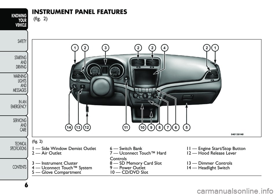
INSTRUMENT PANEL FEATURES(fig. 2)(fig. 2)1 — Side Window Demist Outlet 6 — Switch Bank 11 — Engine Start/Stop Button
2 — Air Outlet 7 — Uconnect Touch™ Hard
Controls 12 — Hood Release Lever
3 — Instrument Cluster 8 — SD Memory Card Slot13 — Dimmer Controls
4 — Uconnect Touch™ System 9 — Power Outlet 14 — Headlight Switch
5 — Glove Compartment 10 — CD/DVD Slot
6
KNOWING YOUR
VEHICLE
SAFETY
S
TARTING AND
DRIVING
WARNING LIGHTSAND
MESSAGES
IN AN
EMERGENCY
SERVICING AND
CARETECHNICAL
SPECIFICATIONSCONTENTS
Page 13 of 352
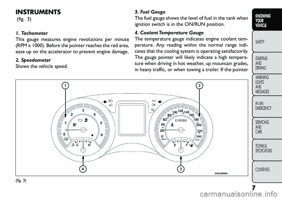
INSTRUMENTS(fig. 3)
1. Tachometer
This gauge measures engine revolutions per minute
(RPM x 1000). Before the pointer reaches the red area,
ease up on the accelerator to prevent engine damage.
2. Speedometer
Shows the vehicle speed. 3. Fuel Gauge
The fuel gauge shows the level of fuel in the tank when
ignition switch is in the ON/RUN position.
4. Coolant Temperature Gauge
The temperature gauge indicates engine coolant tem-
perature. Any reading within the normal range indi-
cates that the cooling system is operating satisfactorily.
The gauge pointer will likely indicate a high tempera-
ture when driving in hot weather, up mountain grades,
in heavy traffic, or when towing a trailer. If the pointer(fig. 3)
7
KNOWING
YOUR
VEHICLE
SAFETY
S
TARTING
AND
DRIVING
WARNING
LIGHTS
AND
MESSAGES
IN AN
EMERGENCY
SERVICING
AND
CARETECHNICAL
SPECIFICATIONSCONTENTS
Page 14 of 352
rises to the “H” mark, safely pull over and stop the
vehicle. If the Air Conditioning A/C system is on, turn
it off. Also, shift the transmission into NEUTRAL and
idle the vehicle. If the needle remains on the “H” mark,
turn the engine OFF immediately and call for service.
Do not leave your vehicle unattended
with the engine running, as you would not
be able to react to the temperature indi-
cator light if the engine overheats. A WORD ABOUT YOUR KEYS
Your vehicle uses a keyless ignition system. This system
consists of a Key Fob with Remote Keyless Entry (RKE)
transmitter and a Keyless Ignition Node (KIN).
Keyless Enter-N-Go Feature™
This vehicle is equipped with the Keyless Enter-N-
Go™ feature, refer to “Starting Procedures” in “Start-
ing And Driving” for further information.
KEYLESS IGNITION NODE (KIN)
This feature allows the driver to operate the ignition
switch with the push of a button, as long as the Remote
Keyless Entry (RKE) transmitter is in the passenger
compartment.
The Keyless Ignition Node (KIN) has four operating
positions, three of which are labeled and will illuminate
when in position. The three positions are OFF, ACC,
and ON/RUN. The fourth position is START. During
start RUN will illuminate.
8
KNOWING YOUR
VEHICLE
SAFETY
S
TARTING AND
DRIVING
WARNING LIGHTSAND
MESSAGES
IN AN
EMERGENCY
SERVICING AND
CARETECHNICAL
SPECIFICATIONSCONTENTS
Page 15 of 352
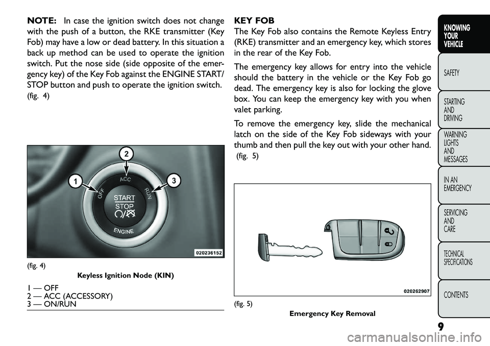
NOTE:In case the ignition switch does not change
with the push of a button, the RKE transmitter (Key
Fob) may have a low or dead battery. In this situation a
back up method can be used to operate the ignition
switch. Put the nose side (side opposite of the emer-
gency key) of the Key Fob against the ENGINE START/
STOP button and push to operate the ignition switch.
(fig. 4) KEY FOB
The Key Fob also contains the Remote Keyless Entry
(RKE) transmitter and an emergency key, which stores
in the rear of the Key Fob.
The emergency key allows for entry into the vehicle
should the battery in the vehicle or the Key Fob go
dead. The emergency key is also for locking the glove
box. You can keep the emergency key with you when
valet parking.
To remove the emergency key, slide the mechanical
latch on the side of the Key Fob sideways with your
thumb and then pull the key out with your other hand.
(fig. 5)(fig. 4) Keyless Ignition Node (KIN)1 — OFF
2 — ACC (ACCESSORY)
3 — ON/RUN
(fig. 5)
Emergency Key Removal
9
KNOWING
YOUR
VEHICLE
SAFETY
S
TARTING
AND
DRIVING
WARNING
LIGHTS
AND
MESSAGES
IN AN
EMERGENCY
SERVICING
AND
CARETECHNICAL
SPECIFICATIONSCONTENTS
Page 16 of 352
NOTE:You can insert the double-sided emergency
key into the lock cylinders with either side up.
IGNITION OR ACCESSORY ON MESSAGE
Opening the driver's door when the ignition is in ACC
or ON (engine not running), a chime will sound to
remind you to cycle the ignition to OFF. In addition to
the chime, the ignition or accessory on message will
display in the cluster.
NOTE: With the Uconnect Touch™ system, the
power window switches, radio, power sunroof (for
versions/markets, where provided), and power outlets
will remain active for up to 10 minutes after the ignition
is cycled to the OFF position. Opening either front
door will cancel this feature. The time for this feature is
programmable. Refer to “Uconnect Touch™ Settings”
in “Knowing Your Vehicle” for further information.
WARNING!
Bef
ore exiting a vehicle, always apply
the parking brake, shift the transmission
into PARK, and remove the Key Fob from the
ignition. When leaving the vehicle, always lock
your vehicle.
Never leave children alone in a vehicle, or with
access to an unlocked vehicle.
Allowing children to be in a vehicle unattended
is dangerous for a number of reasons. A child or
others could be seriously or fatally injured. Chil-
dren should be warned not to touch the parking
brake, brake pedal or the shift lever.
Do not leave the Key Fob in or near the vehicle,
and do not leave the ignition in the ACC or
ON/RUN position. A child could operate power
windows, other controls, or move the vehicle.
Do not leave children or animals inside parked
vehicles in hot weather. Interior heat build-up
may cause serious injury or death.An unlocked car is an invitation to
thieves. Always remove the Key Fob from
vehicle, cycle the ignition OFF and lock
all doors when leaving the vehicle unattended.
10
KNOWING YOUR
VEHICLE
SAFETY
S
TARTING AND
DRIVING
WARNING LIGHTSAND
MESSAGES
IN AN
EMERGENCY
SERVICING AND
CARETECHNICAL
SPECIFICATIONSCONTENTS
Page 17 of 352

SENTRY KEY®
The Sentry Key
®Immobilizer system prevents unau-
thorized vehicle operation by disabling the engine. The
system does not need to be armed or activated. Op-
eration is automatic, regardless of whether the vehicle
is locked or unlocked.
The system uses a Key Fob with Remote Keyless Entry
(RKE) transmitter, a Keyless Ignition Node (KIN) and a
RF receiver to prevent unauthorized vehicle operation.
Therefore, only Key Fobs that are programmed to the
vehicle can be used to start and operate the vehicle.
After cycling the ignition to the ON/RUN position, the
Vehicle Security Light will turn on for three seconds for
a bulb check. If the light remains on after the bulb
check, it indicates that there is a problem with the
electronics. In addition, if the light begins to flash after
the bulb check, it indicates that someone used an
invalid Key Fob to start the engine. Either of these
conditions will result in the engine being shut off after
two seconds.
If the Vehicle Security Light turns on during normal
vehicle operation (vehicle running for longer than 10
seconds), it indicates that there is a fault in the elec-
tronics. Should this occur, have the vehicle serviced as
soon as possible by an authorized dealer. All of the Key Fobs provided with your new vehicle
have been programmed to the vehicle electronics.
REPLACEMENT KEYS
NOTE:
Only Key Fobs that are programmed to the
vehicle electronics can be used to start and operate the
vehicle. Once a Key Fob is programmed to a vehicle, it
cannot be programmed to any other vehicle.
Always remove the Key Fobs from the
vehicle and lock all doors when leaving
the vehicle unattended.
With Keyless Enter-N-Go™, always remember
to place the ignition in the OFF position.
Duplication of Key Fobs may be performed at an
authorized dealer, this procedure consists of program-
ming a blank Key Fob to the vehicle electronics. A blank
Key Fob is one that has never been programmed.
NOTE: When having the Sentry Key
®Immobilizer
system serviced, bring all vehicle Key Fobs with you to
the authorized dealer.
CUSTOMER KEY PROGRAMMING
Programming Key Fobs or RKE transmitters may be
performed at an authorized dealer.
11
KNOWING
YOUR
VEHICLE
SAFETY
STARTING
AND
DRIVING
WARNING
LIGHTS
AND
MESSAGES
IN AN
EMERGENCY
SERVICING
AND
CARETECHNICAL
SPECIFICATIONSCONTENTS
Page 18 of 352
GENERAL INFORMATION
The Sentry Key
®Immobilizer system will be used in
the following European countries, which apply Direc-
tive 1999/5/EC: Austria, Belgium, Czech Republic,
Denmark, Finland, France, Germany, Greece, Hungary,
Ireland, Italy, Luxembourg, Netherlands, Norway, Po-
land, Portugal, Romania, Russian Federation, Slovenia,
Spain, Sweden, Switzerland, Yugoslavia, and United
Kingdom.
Operation is subject to the following conditions:
This device may not cause harmful interference.
This device must accept any interference that may be received, including interference that may cause un-
desired operation. REMOTE KEYLESS ENTRY (RKE)
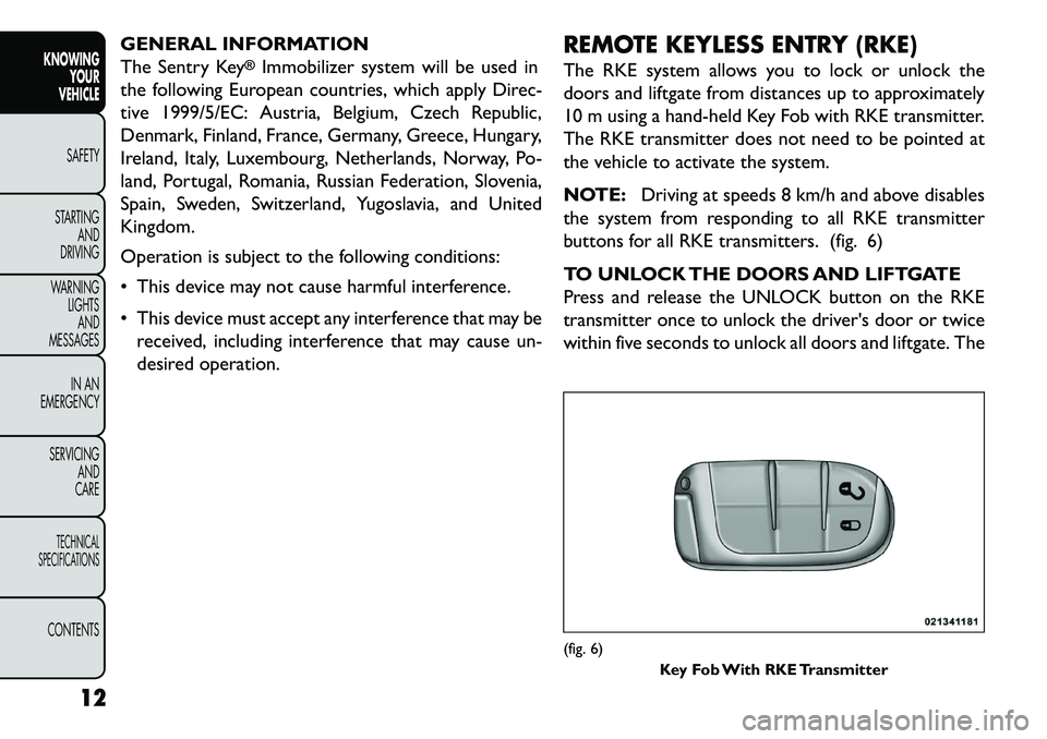
The RKE system allows you to lock or unlock the
doors and liftgate from distances up to approximately
10 m using a hand-held Key Fob with RKE transmitter.
The RKE transmitter does not need to be pointed at
the vehicle to activate the system.
NOTE:
Driving at speeds 8 km/h and above disables
the system from responding to all RKE transmitter
buttons for all RKE transmitters. (fig. 6)
TO UNLOCK THE DOORS AND LIFTGATE
Press and release the UNLOCK button on the RKE
transmitter once to unlock the driver's door or twice
within five seconds to unlock all doors and liftgate. The
(fig. 6) Key Fob With RKE Transmitter
12
KNOWING YOUR
VEHICLE
SAFETY
S
TARTING AND
DRIVING
WARNING LIGHTSAND
MESSAGES
IN AN
EMERGENCY
SERVICING AND
CARETECHNICAL
SPECIFICATIONSCONTENTS
Page 19 of 352
turn signal lights will flash to acknowledge the unlock
signal. The illuminated entry system will also turn on.
If the vehicle is equipped with Passive Entry, refer to
“Keyless EnterNGo™ (for versions/markets, where
provided)” under “Knowing Your Vehicle” for further
information.
Remote Key Unlock, Driver Door/All Doors
1st Press
This feature lets you program the system to unlock
either the driver's door or all doors on the first press of
the UNLOCK button on the RKE transmitter. To
change the current setting, refer to “Uconnect
Touch™ Settings” in “Knowing Your Vehicle” for fur-
ther information.
Flash Lights With Lock
This feature will cause the turn signal lights to flash
when the doors are locked or unlocked with the RKE
transmitter. This feature can be turned on or turned
off. To change the current setting, refer to “Uconnect
Touch™ Settings” in “Knowing Your Vehicle” for fur-
ther information.
Turn Headlights On With Remote Key Unlock
This feature activates the headlights for up to 90
seconds when the doors are unlocked with the RKE
transmitter. The time for this feature is programmable
on vehicles equipped through Uconnect Touch™. Tochange the current setting, refer to “Uconnect
Touch™ Settings” in “Knowing Your Vehicle” for fur-
ther information.
TO LOCK THE DOORS AND LIFTGATE
Press and release the LOCK button on the RKE trans-
mitter to lock all doors and liftgate. The turn signal
lights will flash to acknowledge the signal.
If the vehicle is equipped with Passive Entry, refer to
“Keyless EnterNGo™ (for versions/markets, where
provided)” under “Knowing Your Vehicle” for further
information.
Programming Additional Transmitters
Programming Key Fobs or RKE transmitters may be
performed at an authorized dealer.
TRANSMITTER BATTERY REPLACEMENT
The recommended replacement battery is one
CR2032 battery.
NOTE:
Perchlorate Material — special handling may apply.
Batteries could contain dangerous materials. Please
dispose of them according to respect for environ-
ment and local laws.
Used batteries are harmful to the environment. You can dispose of them either in the correct containers
13
KNOWING
YOUR
VEHICLE
SAFETY
STARTING
AND
DRIVING
WARNING
LIGHTS
AND
MESSAGES
IN AN
EMERGENCY
SERVICING
AND
CARETECHNICAL
SPECIFICATIONSCONTENTS
Page 20 of 352
as specified by law or by taking them to a FIAT
Dealership, which will deal with their disposal.
Do not touch the battery terminals that are on the back housing or the printed circuit board.
1. Remove the emergency key by sliding the mechani- cal latch on the back of the RKE transmitter side-
ways with your thumb and then pull the key out with
your other hand.
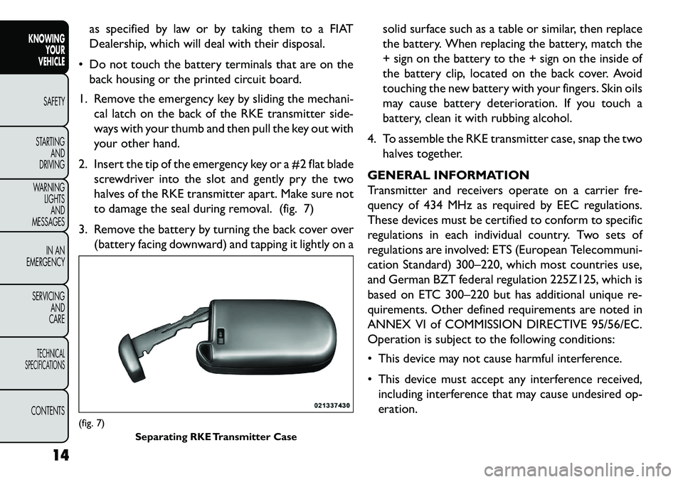
2. Insert the tip of the emergency key or a #2 flat blade screwdriver into the slot and gently pry the two
halves of the RKE transmitter apart. Make sure not
to damage the seal during removal. (fig. 7)
3. Remove the battery by turning the back cover over (battery facing downward) and tapping it lightly on a solid surface such as a table or similar, then replace
the battery. When replacing the battery, match the
+ sign on the battery to the + sign on the inside of
the battery clip, located on the back cover. Avoid
touching the new battery with your fingers. Skin oils
may cause battery deterioration. If you touch a
battery, clean it with rubbing alcohol.
4. To assemble the RKE transmitter case, snap the two halves together.
GENERAL INFORMATION
Transmitter and receivers operate on a carrier fre-
quency of 434 MHz as required by EEC regulations.
These devices must be certified to conform to specific
regulations in each individual country. Two sets of
regulations are involved: ETS (European Telecommuni-
cation Standard) 300–220, which most countries use,
and German BZT federal regulation 225Z125, which is
based on ETC 300–220 but has additional unique re-
quirements. Other defined requirements are noted in
ANNEX VI of COMMISSION DIRECTIVE 95/56/EC.
Operation is subject to the following conditions:
This device may not cause harmful interference.
This device must accept any interference received, including interference that may cause undesired op-
eration.(fig. 7) Separating RKE Transmitter Case
14
KNOWING YOUR
VEHICLE
SAFETY
S
TARTING AND
DRIVING
WARNING LIGHTSAND
MESSAGES
IN AN
EMERGENCY
SERVICING AND
CARETECHNICAL
SPECIFICATIONSCONTENTS