headlights FIAT FREEMONT 2013 Owner handbook (in English)
[x] Cancel search | Manufacturer: FIAT, Model Year: 2013, Model line: FREEMONT, Model: FIAT FREEMONT 2013Pages: 352, PDF Size: 5.22 MB
Page 47 of 352
switches, radio, Uconnect™ phone system (for
versions/markets, where provided), DVD video system
(for versions/markets, where provided), power sunroof
(for versions/markets, where provided), and power
outlets will remain active for up to 10 minutes after the
ignition is cycled OFF. Opening either front vehicle
door will cancel this feature. To change the Engine Off
Power Delay status press the 0 seconds, 45 seconds, 5
minutes or 10 minutes soft-key followed by pressing
the arrow back soft-key.
Headlight Off Delay (for versions/markets,
where provided)
When this feature is selected, the driver can choose to
have the headlights remain on for 0, 30, 60, or 90
seconds when exiting the vehicle. To change the Head-
light Off Delay status press the 0, 30, 60 or 90 soft-key
followed by pressing the arrow back soft-key.Compass Settings
Variance (for versions/markets, where provided)
Compass Variance is the difference between Magnetic
North and Geographic North. To compensate for the
differences the variance should be set for the zone
where the vehicle is driven, per the zone map. Once
properly set, the compass will automatically compen-
sate for the differences, and provide the most accurate
compass heading.
NOTE:
Keep magnetic materials away from the top
of the instrument panel, such as iPod's, Mobile Phones,
Laptops and Radar Detectors. This is where the com-
pass module is located, and it can cause interference
with the compass sensor, and it may give false readings.
(fig. 14)
41
KNOWING
YOUR
VEHICLE
SAFETY
STARTING
AND
DRIVING
WARNING
LIGHTS
AND
MESSAGES
IN AN
EMERGENCY
SERVICING
AND
CARETECHNICAL
SPECIFICATIONSCONTENTS
Page 81 of 352
LIGHTS
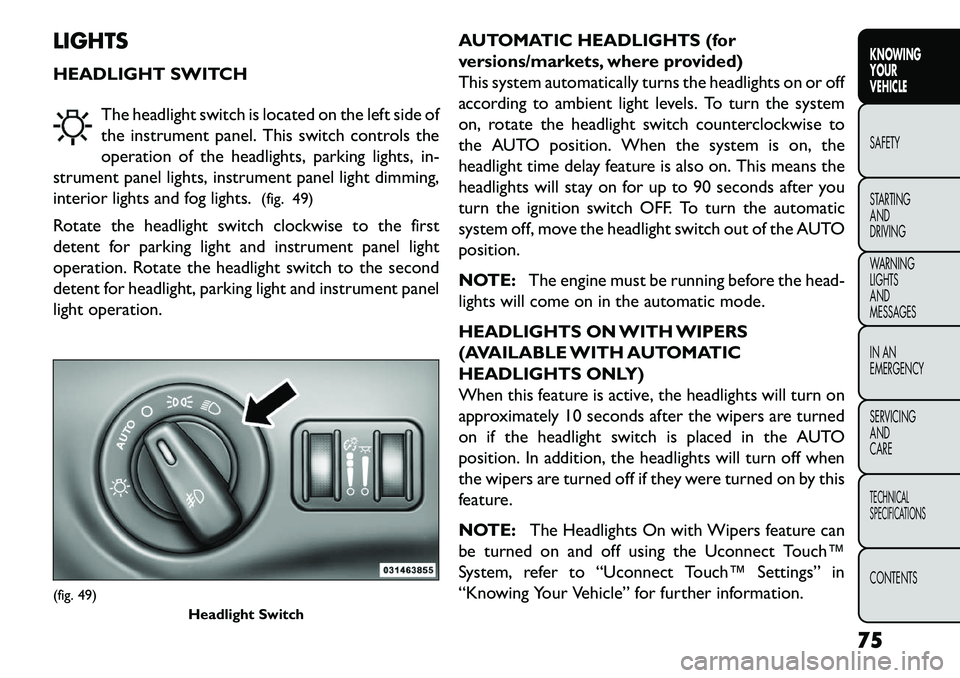
HEADLIGHT SWITCHThe headlight switch is located on the left side of
the instrument panel. This switch controls the
operation of the headlights, parking lights, in-
strument panel lights, instrument panel light dimming,
interior lights and fog lights. (fig. 49)
Rotate the headlight switch clockwise to the first
detent for parking light and instrument panel light
operation. Rotate the headlight switch to the second
detent for headlight, parking light and instrument panel
light operation. AUTOMATIC HEADLIGHTS (for
versions/markets, where provided)
This system automatically turns the headlights on or off
according to ambient light levels. To turn the system
on, rotate the headlight switch counterclockwise to
the AUTO position. When the system is on, the
headlight time delay feature is also on. This means the
headlights will stay on for up to 90 seconds after you
turn the ignition switch OFF. To turn the automatic
system off, move the headlight switch out of the AUTO
position.
NOTE:
The engine must be running before the head-
lights will come on in the automatic mode.
HEADLIGHTS ON WITH WIPERS
(AVAILABLE WITH AUTOMATIC
HEADLIGHTS ONLY)
When this feature is active, the headlights will turn on
approximately 10 seconds after the wipers are turned
on if the headlight switch is placed in the AUTO
position. In addition, the headlights will turn off when
the wipers are turned off if they were turned on by this
feature.
NOTE: The Headlights On with Wipers feature can
be turned on and off using the Uconnect Touch™
System, refer to “Uconnect Touch™ Settings” in
“Knowing Your Vehicle” for further information.(fig. 49) Headlight Switch
75
KNOWING
YOUR
VEHICLE
SAFETY
S
TARTING
AND
DRIVING
WARNING
LIGHTS
AND
MESSAGES
IN AN
EMERGENCY
SERVICING
AND
CARETECHNICAL
SPECIFICATIONSCONTENTS
Page 82 of 352
HEADLIGHT TIME DELAY
This feature provides the safety of headlight illumina-
tion for up to 90 seconds when leaving your vehicle in
an unlit area.
To activate the delay feature, turn OFF the ignition
switch while the headlights are still on. Then, turn off
the headlights within 45 seconds. The delay interval
begins when the headlight switch is turned off.
NOTE:The lights must be turned off within 45
seconds of turning the ignition OFF to activate this
feature.
If you turn the headlights, park lights or ignition switch
ON again, the system will cancel the delay.
If you turn the headlights off before the ignition, they
will turn off in the normal manner.
NOTE: The Headlight Time Delay is programmable
using the Uconnect Touch™ System, refer to
“Uconnect Touch™ Settings” in “Knowing Your Ve-
hicle” for further information.
LIGHTS-ON REMINDER
If the headlights or parking lights are on after the
ignition is turned OFF, a chime will sound to alert the
driver when the driver's door is opened. FRONT AND REAR FOG LIGHTS (for
versions/markets, where provided)
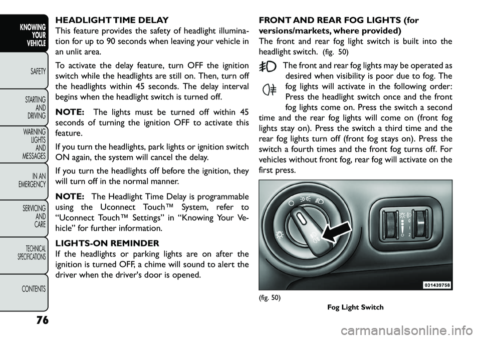
The front and rear fog light switch is built into the
headlight switch.
(fig. 50)
The front and rear fog lights may be operated as desired when visibility is poor due to fog. The
fog lights will activate in the following order:
Press the headlight switch once and the front
fog lights come on. Press the switch a second
time and the rear fog lights will come on (front fog
lights stay on). Press the switch a third time and the
rear fog lights turn off (front fog stays on). Press the
switch a fourth times and the front fog turns off. For
vehicles without front fog, rear fog will activate on the
first press.
(fig. 50) Fog Light Switch
76
KNOWINGYOUR
VEHICLE
SAFETY
S
TARTING AND
DRIVING
WARNING LIGHTSAND
MESSAGES
IN AN
EMERGENCY
SERVICING AND
CARETECHNICAL
SPECIFICATIONSCONTENTS
Page 83 of 352

An indicator light in the instrument cluster illuminates
when the fog lights are turned on.
MULTIFUNCTION LEVER
The multifunction lever controls the operation of the
turn signals, headlight beam selection and passing lights.
The multifunction lever is located on the left side of the
steering column.(fig. 51)
TURN SIGNALS
Move the multifunction lever up or down and the
arrows on each side of the instrument cluster flash to
show proper operation of the front and rear turn signal
lights. NOTE:
If either light remains on and does not flash, or there
is a very fast flash rate, check for a defective outside
light bulb. If an indicator fails to light when the lever
is moved, it would suggest that the indicator bulb is
defective.
A “Turn Signal On” message will appear in the EVIC (for versions/markets, where provided) and a con-
tinuous chime will sound if the vehicle is driven more
than 1.6 km with either turn signal on.
LANE CHANGE ASSIST
Tap the lever up or down once, without moving beyond
the detent, and the turn signal (right or left) will flash
three times then automatically turn off.
HIGH/LOW BEAM SWITCH
Push the multifunction lever away from you to switch
the headlights to high beam. Pull the multifunction lever
toward you to switch the headlights back to low beam.
FLASH-TO-PASS
You can signal another vehicle with your headlights by
lightly pulling the multifunction lever toward you. This
will turn on the high beams headlights until the lever is
released.(fig. 51) Multifunction Lever
77
KNOWING
YOUR
VEHICLE
SAFETY
S
TARTING
AND
DRIVING
WARNING
LIGHTS
AND
MESSAGES
IN AN
EMERGENCY
SERVICING
AND
CARETECHNICAL
SPECIFICATIONSCONTENTS
Page 84 of 352
INTERIOR LIGHTS
The interior lights come on when a door is opened.
To protect the battery, the interior lights will turn off
automatically 10 minutes after the ignition switch is
moved to the LOCK position. This will occur if the
interior lights were switched on manually or are on
because a door is open. This includes the glove box
light, but not the trunk light. To restore interior light
operation, either turn the ignition switch ON or cycle
the light switch.
DIMMER CONTROLS
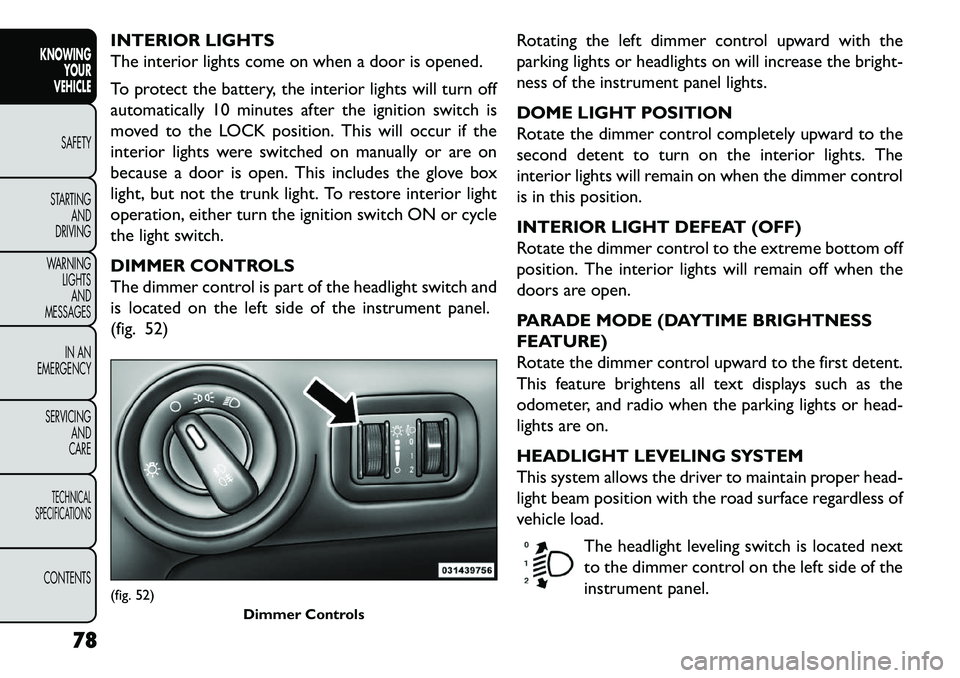
The dimmer control is part of the headlight switch and
is located on the left side of the instrument panel.
(fig. 52)Rotating the left dimmer control upward with the
parking lights or headlights on will increase the bright-
ness of the instrument panel lights.
DOME LIGHT POSITION
Rotate the dimmer control completely upward to the
second detent to turn on the interior lights. The
interior lights will remain on when the dimmer control
is in this position.
INTERIOR LIGHT DEFEAT (OFF)
Rotate the dimmer control to the extreme bottom off
position. The interior lights will remain off when the
doors are open.
PARADE MODE (DAYTIME BRIGHTNESS
FEATURE)
Rotate the dimmer control upward to the first detent.
This feature brightens all text displays such as the
odometer, and radio when the parking lights or head-
lights are on.
HEADLIGHT LEVELING SYSTEM
This system allows the driver to maintain proper head-
light beam position with the road surface regardless of
vehicle load.
The headlight leveling switch is located next
to the dimmer control on the left side of the
instrument panel.(fig. 52) Dimmer Controls
78
KNOWINGYOUR
VEHICLE
SAFETY
S
TARTING AND
DRIVING
WARNING LIGHTSAND
MESSAGES
IN AN
EMERGENCY
SERVICING AND
CARETECHNICAL
SPECIFICATIONSCONTENTS
Page 88 of 352
If you activate the washer while the wiper control is in
the OFF position, the wipers will operate for two or
three wipe cycles and then turn OFF.
WARNING!
Sudden loss of visibility through the
win
dshield could lead to a collision. You
might not see other vehicles or other obstacles.To
avoid sudden icing of the windshield during freez-
ing weather, warm the windshield with the de-
froster before and during windshield washer use.
MIST FEATURE
Push the washer knob, located on the end of the
multifunction lever, inward to the first detent to acti-
vate a single wipe cycle to clear the windshield of road
mist or spray from a passing vehicle. The wipers will
continue to operate until you release the lever.
NOTE: The mist feature does not activate the
washer pump; therefore, no washer fluid will be
sprayed on the windshield. The wash function must be
used in order to spray the windshield with washer fluid. HEADLIGHT WASHERS (for
versions/markets, where
provided)
The Headlight Washers are recessed into the top of
the fascia, centrally located below each headlight.
The windshield wiper/washer control lever operates
the headlight washers when the ignition switch is in the
ON position and the headlights are ON. The lever is
located on the left side of the steering column.
To use the headlight washers, push the washer knob,
located on the end of the multifunction lever, inward to
the second detent to activate the windshield washers
and release it. When this is done, the two stationary
washer nozzles at each headlight spray one timed
high-pressure spray of washer fluid onto each headlight
lens. In addition, the windshield washers will spray the
windshield and the windshield wipers will cycle.
NOTE:
After turning the ignition switch and head-
lights ON, the headlight washers will operate on the
first spray of the windshield washer and then every
eleventh spray after that.
82
KNOWING YOUR
VEHICLE
SAFETY
S
TARTING AND
DRIVING
WARNING LIGHTSAND
MESSAGES
IN AN
EMERGENCY
SERVICING AND
CARETECHNICAL
SPECIFICATIONSCONTENTS
Page 246 of 352
cycles, and the vehicle has been driven several kilome-
ters at speeds greater than 48 km/h, see your autho-
rized dealer as soon as possible to have the problem
diagnosed and corrected.
NOTE:
The “ESC Off Indicator Light” and the “ESC
Activation/Malfunction Indicator Light” come on mo-
mentarily each time the ignition switch is turned to
ON/RUN.
Each time the ignition is turned to ON/RUN, the ESC
system will be ON, even if it was turned off previously.
The ESC system will make buzzing or clicking sounds
when it is active. This is normal; the sounds will stop
when ESC becomes inactive following the maneuver
that caused the ESC activation.
4. Turn Signal Indicator LightThe left or right arrow will flash in unison
with the corresponding front and rear turn
signal lights when the turn signal switch is
operated. (Refer to “Lights” in “Knowing
Your Vehicle” for further information).
NOTE:
A chime will sound if the vehicle is driven more than
1.6 km with either turn signal on. Check for an inoperative outside light bulb if either
indicator flashes at a rapid rate.
5. High Beam Indicator
This light shows that the high beam headlights
are on. Pull the multifunction lever on the left
side of the steering column toward you to switch to
low beam. (Refer to “Lights” in “Knowing Your Vehicle”
for further information).
6. Front Fog Light Indicator (for versions/markets,
where provided) This indicator will illuminate when the front fog
lights are on. (Refer to “Lights” in “Knowing
Your Vehicle” for further information).
7. Odometer Display / Electronic Vehicle Informa-
tion Center (EVIC) Display
Odometer
The odometer display shows the total distance the
vehicle has been driven.
Electronic Vehicle Information Center (EVIC) Dis-
play
The Electronic Vehicle Information Center (EVIC) fea-
tures a driver-interactive display that is located in the
instrument cluster. For further information, refer to
“Electronic Vehicle Information Center (EVIC)” in
“Knowing Your Vehicle”.
240
KNOWING YOUR
VEHICLE
SAFETY
STARTING AND
DRIVING
WARNING LIGHTSAND
MESSA
GES
IN AN
EMERGENC
Y
SERVICING AND
CARETECHNICAL
SPECIFICATIONSCONTENTS
Page 247 of 352
8. Park/Headlight ON IndicatorThis indicator will illuminate when the park
lights or headlights are turned on. (Refer to
“Lights” in “Knowing Your Vehicle” for fur-
ther information).
9. Tire Pressure Monitoring Telltale Light Each tire, including the spare (if provided),
should be checked monthly when cold and
inflated to the inflation pressure recom-
mended by the vehicle manufacturer on the
vehicle placard or tire inflation pressure label.
As an added safety feature, your vehicle has been
equipped with a tire pressure monitoring system
(TPMS) that illuminates a low tire pressure telltale
when one or more of your tires is significantly under-
inflated. Accordingly, when the low tire pressure tell-
tale light illuminates, you should stop and check your
tires as soon as possible, and inflate them to the proper
pressure. Driving on a significantly under-inflated tire
causes the tire to overheat and can lead to tire failure.
Under-inflation also reduces fuel efficiency and tire
tread life, and may affect the vehicle’s handling and
stopping ability. Please note that the TPMS is not a substitute for
proper tire maintenance, and it is the driver’s respon-
sibility to maintain correct tire pressure, even if under-
inflation has not reached the level to trigger illumina-
tion of the TPMS low tire pressure telltale.
Your vehicle has also been equipped with a TPMS
malfunction indicator to indicate when the system is
not operating properly. The TPMS malfunction indica-
tor is combined with the low tire pressure telltale.
When the system detects a malfunction, the telltale
will flash for approximately one minute and then re-
main continuously illuminated. This sequence will con-
tinue upon subsequent vehicle start-ups as long as the
malfunction exists. When the malfunction indicator is
illuminated, the system may not be able to detect or
signal low tire pressure as intended. TPMS malfunctions
may occur for a variety of reasons, including the instal-
lation of replacement or alternate tires or wheels on
the vehicle that prevent the TPMS from functioning
properly. Always check the TPMS malfunction telltale
light after replacing one or more tires or wheels on
your vehicle to ensure that the replacement or alter-
nate tires and wheels allow the TPMS to continue to
function properly.
241KNOWING
YOUR
VEHICLE
SAFETY
STARTING
AND
DRIVING
WARNING
LIGHTS
AND
MESSA
GES
IN AN
EMERGENC Y
SERVICING
AND
CARETECHNICAL
SPECIFICATIONSCONTENTS
Page 292 of 352
Periodic Checks
Every1,000 km or before long journeys, check and, if
necessary, restore:
engine coolant;
brake fluid;
windshield washer fluid level;
power steering fluid;
tire inflation pressure and condition;
operation of lighting system (headlights, direction indicators, hazard warning lights, etc.);
operation of windshield washer/wiper system and positioning/wear of windshield/rear window wiper
blades.
Every 3,000 km, check and top up, if required, the
engine oil level.
Heavy-Duty Use Of The Car
If the car is used mainly under one of the following
conditions:
towing a trailer or caravan;
dusty roads;
short, repeated journeys (less than 7-8 km) at sub- zero outside temperatures; engine often idling or driving long distances at low
speeds or long periods of idleness.
You should perform the following inspections more
frequently than shown on the Scheduled Servicing Plan:
check front disc brake pad conditions and wear;
check cleanliness of hood and trunk locks, cleanli- ness and lubrication of linkage;
visually inspect conditions of: engine, transmission, pipes and hoses (exhaust - fuel system - brakes) and
rubber elements (boots - sleeves - bushes - etc.);
check battery charge and battery fluid level (electro- lyte);
visually inspect condition of the accessory drive belts;
check and, if necessary, change engine oil and replace oil filter;
check and, if necessary, replace pollen filter;
check and, if necessary, replace air cleaner.
MAINTENANCE SCHEDULE — DIESEL
ENGINE
Required Maintenance Intervals
Refer to the Maintenance Schedules on the following
pages for the required maintenance intervals.
286
KNOWING YOUR
VEHICLE
SAFETY
STARTING AND
DRIVING
WARNING LIGHTSAND
MESSAGES
IN AN
EMERGENCY
SERVICING AND
C
ARETECHNICAL
SPECIFICATIONSCONTENTS
Page 293 of 352
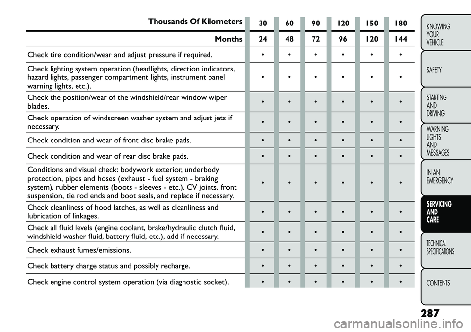
Thousands Of Kilometers30 60 90 120 150 180
Months 24 48 72 96 120 144
Check tire condition/wear and adjust pressure if required.
Check lighting system operation (headlights, direction indicators,
hazard lights, passenger compartment lights, instrument panel
warning lights, etc.).
Check the position/wear of the windshield/rear window wiper
blades.
Check operation of windscreen washer system and adjust jets if
necessary.
Check condition and wear of front disc brake pads.
Check condition and wear of rear disc brake pads.
Conditions and visual check: bodywork exterior, underbody
protection, pipes and hoses (exhaust - fuel system - braking
system), rubber elements (boots - sleeves - etc.), CV joints, front
suspension, tie rod ends and boot seals, and replace if necessary.
Check cleanliness of hood latches, as well as cleanliness and
lubrication of linkages.
Check all fluid levels (engine coolant, brake/hydraulic clutch fluid,
windshield washer fluid, battery fluid, etc.), add if necessary.
Check exhaust fumes/emissions.
Check battery charge status and possibly recharge.
Check engine control system operation (via diagnostic socket).
287
KNOWING
YOUR
VEHICLE
SAFETY
STARTING
AND
DRIVING
WARNING
LIGHTS
AND
MESSAGES
IN AN
EMERGENCY
SERVICING
AND
CARETECHNICAL
SPECIFICATIONSCONTENTS