air conditioning FIAT FREEMONT 2013 Owner handbook (in English)
[x] Cancel search | Manufacturer: FIAT, Model Year: 2013, Model line: FREEMONT, Model: FIAT FREEMONT 2013Pages: 352, PDF Size: 5.22 MB
Page 14 of 352
rises to the “H” mark, safely pull over and stop the
vehicle. If the Air Conditioning A/C system is on, turn
it off. Also, shift the transmission into NEUTRAL and
idle the vehicle. If the needle remains on the “H” mark,
turn the engine OFF immediately and call for service.
Do not leave your vehicle unattended
with the engine running, as you would not
be able to react to the temperature indi-
cator light if the engine overheats. A WORD ABOUT YOUR KEYS
Your vehicle uses a keyless ignition system. This system
consists of a Key Fob with Remote Keyless Entry (RKE)
transmitter and a Keyless Ignition Node (KIN).
Keyless Enter-N-Go Feature™
This vehicle is equipped with the Keyless Enter-N-
Go™ feature, refer to “Starting Procedures” in “Start-
ing And Driving” for further information.
KEYLESS IGNITION NODE (KIN)
This feature allows the driver to operate the ignition
switch with the push of a button, as long as the Remote
Keyless Entry (RKE) transmitter is in the passenger
compartment.
The Keyless Ignition Node (KIN) has four operating
positions, three of which are labeled and will illuminate
when in position. The three positions are OFF, ACC,
and ON/RUN. The fourth position is START. During
start RUN will illuminate.
8
KNOWING YOUR
VEHICLE
SAFETY
S
TARTING AND
DRIVING
WARNING LIGHTSAND
MESSAGES
IN AN
EMERGENCY
SERVICING AND
CARETECHNICAL
SPECIFICATIONSCONTENTS
Page 69 of 352
CLIMATE CONTROLS
GENERAL OVERVIEW
The air conditioning and heating system is designed to
make you comfortable in all types of weather. This
system can be operated through either the Automatic
Climate Controls on the instrument panel or through
the Uconnect Touch™ system display.
When the Uconnect Touch™ system is in different
modes (Radio, Player, Settings, More, etc.) the driver
and passenger temperature settings will be indicated at
the top of the display.
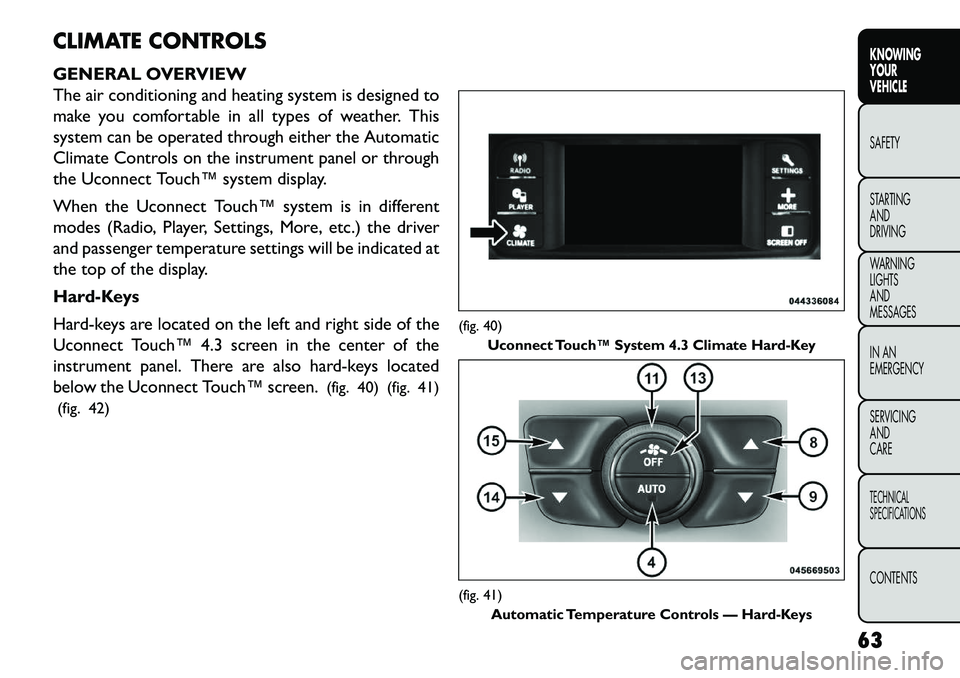
Hard-Keys
Hard-keys are located on the left and right side of the
Uconnect Touch™ 4.3 screen in the center of the
instrument panel. There are also hard-keys located
below the Uconnect Touch™ screen.(fig. 40) (fig. 41)
(fig. 42)
(fig. 40) Uconnect Touch™ System 4.3 Climate Hard-Key(fig. 41)
Automatic Temperature Controls — Hard-Keys
63
KNOWING
YOUR
VEHICLE
SAFETY
S
TARTING
AND
DRIVING
WARNING
LIGHTS
AND
MESSAGES
IN AN
EMERGENCY
SERVICING
AND
CARETECHNICAL
SPECIFICATIONSCONTENTS
Page 73 of 352
NOTE:BI-LEVEL mode is designed under comfort
conditions to provide cooler air out of the panel
outlets and warmer air from the floor outlets.
Floor Mode Air comes from the floor outlets. A slight
amount of air is directed through the defrost
and side window demister outlets.
Mix Mode Air comes from the floor, defrost and side win-
dow demist outlets. This mode works best in
cold or snowy conditions.
Defrost Mode Air comes from the windshield and side window
demist outlets. Use Defrost mode with maxi-
mum temperature settings for best windshield and side
window defrosting and defogging. When the defrost
mode is selected, the blower level may will increase.
13. Climate Control OFF Button
Press and release this button to turn the Climate
Control ON/OFF.
14. Driver Temperature Control Down Button
Provides the driver with independent temperature
control. Push the button for cooler temperature set-
tings. NOTE:
In Sync mode, this button will also automati-
cally adjust the passenger temperature setting at the
same time.
15. Driver Temperature Control Up Button
Provides the driver with independent temperature
control. Push the button for warmer temperature
settings.
NOTE: In Sync mode, this button will also automati-
cally adjust the passenger temperature setting at the
same time.
16. Temperature Control (Manual Temperature
Control Only)
Press the temperature soft-key to regulate the tem-
perature of the air inside the passenger compartment.
Moving the temperature bar into the red area, indicates
warmer temperatures. Moving the temperature bar
into the blue area indicates cooler temperatures.
CLIMATE CONTROL FUNCTIONS
A/C (Air Conditioning)
The Air Conditioning (A/C) button allows the opera-
tor to manually activate or deactivate the air condition-
ing system. When the air conditioning system is turned
on, cool dehumidified air will flow through the outlets
into the cabin. For improved fuel economy, press the
A/C button to turn off the air conditioning and manu-
ally adjust the blower and airflow mode settings. Also,
67KNOWING
YOUR
VEHICLE
SAFETY
S
TARTING
AND
DRIVING
WARNING
LIGHTS
AND
MESSAGES
IN AN
EMERGENCY
SERVICING
AND
CARETECHNICAL
SPECIFICATIONSCONTENTS
Page 74 of 352
make sure to select only Panel, Bi-Level or Floor
modes.
NOTE:
For Manual Climate Controls, if the system is in Mix,Floor or Defrost Mode, the A/C can be turned off,
but the A/C system shall remain active to prevent
fogging of the windows.
If fog or mist appears on the windshield or side glass, select Defrost mode and increase blower speed.
If your air conditioning performance seems lower than expected, check the front of the A/C condenser
(located in front of the radiator), for an accumulation
of dirt or insects. Clean with a gentle water spray
from the front of the radiator and through the
condenser.
MAX A/C
MAX A/C sets the control for maximum cooling per-
formance.
Press and release to toggle between MAX A/C and the
prior settings. The soft-key illuminates when MAX A/C
is ON.
In MAX A/C, the blower level and mode position can
be adjusted to desired user settings. Pressing other
settings will cause the MAX A/C operation to switch to the prior settings and the MAX A/C indicator will turn
off.
Recirculation Control
When outside air contains smoke, odors, or
high humidity, or if rapid cooling is desired,
you may wish to recirculate interior air by
pressing the Recirculation control button.
The recirculation indicator will illuminate when this
button is selected. Push the button a second time to
turn off the Recirculation mode and allow outside air
into the vehicle.
NOTE: In cold weather, use of Recirculation mode
may lead to excessive window fogging. The recircula-
tion feature may be unavailable (soft button greyed out)
if conditions exist that could create fogging on the
inside of the windshield. The Recirculation mode is not
allowed in Defrost mode to improve window clearing
operation. Recirculation will be disabled automatically
if these modes are selected. Attempting to use Recir-
culation while in these modes will cause the LED in the
control button to blink and then turn off.
AUTOMATIC TEMPERATURE CONTROL
(ATC) (for versions/markets, where provided)
ATC Hard-keys are located in the center of the instru-
ment panel.
68
KNOWING YOUR
VEHICLE
SAFETY
S
TARTING AND
DRIVING
WARNING LIGHTSAND
MESSAGES
IN AN
EMERGENCY
SERVICING AND
CARETECHNICAL
SPECIFICATIONSCONTENTS
Page 79 of 352
Summer Operation
The engine cooling system in air-conditioned vehicles
must be protected with a high-quality antifreeze cool-
ant to provide proper corrosion protection and to
protect against engine overheating. A solution of 50%
ethylene glycol antifreeze coolant and 50% water is
recommended. Refer to “Maintenance Procedures” in
“Servicing And Care” for proper coolant selection.
Winter Operation
Use of the air Recirculation mode during Winter
months is not recommended because it may cause
window fogging.
Vacation Storage
Any time you store your vehicle or keep it out of
service (i.e., vacation) for two weeks or more, run the
air conditioning system at idle for about five minutes in
the fresh air and high blower setting. This will ensure
adequate system lubrication to minimize the possibility
of compressor damage when the system is started
again.
Window Fogging
Interior fogging on the windshield can be quickly re-
moved by turning the mode selector to Defrost. The
Defrost/Floor mode can be used to maintain a clear
windshield and provide sufficient heating. If side win-
dow fogging becomes a problem, increase the blowerspeed. Vehicle windows tend to fog on the inside in
mild but rainy or humid weather.
NOTE:
Recirculation mode without A/C should not
be used for long periods, as fogging may occur.
Outside Air Intake
Make sure the air intake, located directly in front of the
windshield, is free of obstructions such as leaves.
Leaves collected in the air intake may reduce airflow,
and if they enter the plenum, they could plug the water
drains. In winter months, make sure the air intake is
clear of ice, slush, and snow.
A/C Air Filter
The climate control system filters outside air contain-
ing dust, pollen and some odors. Strong odors cannot
be totally filtered out. Refer to “Maintenance Proce-
dures” in “Servicing And Care” for filter replacement
instructions.
73
KNOWING
YOUR
VEHICLE
SAFETY
STARTING
AND
DRIVING
WARNING
LIGHTS
AND
MESSAGES
IN AN
EMERGENCY
SERVICING
AND
CARETECHNICAL
SPECIFICATIONSCONTENTS
Page 241 of 352
– Extended driving at high RPM should be avoided toprevent excess heat generation. A reduction in ve-
hicle speed may be required to avoid extended
driving at high RPM. Return to a higher gear or
vehicle speed when grade and road conditions allow.
Cooling System
To reduce potential for engine and transmission over-
heating, take the following actions:
City Driving
When stopped for short periods, shift the transmission
into NEUTRAL and increase engine idle speed.
Highway Driving
Reduce speed.
Air Conditioning
Turn off temporarily.
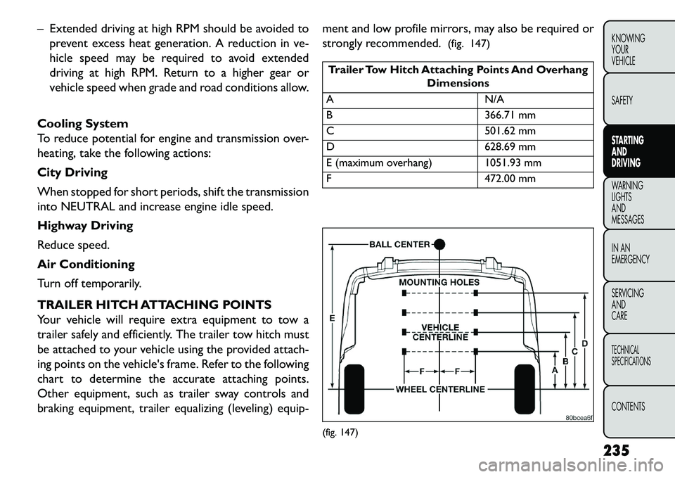
TRAILER HITCH ATTACHING POINTS
Your vehicle will require extra equipment to tow a
trailer safely and efficiently. The trailer tow hitch must
be attached to your vehicle using the provided attach-
ing points on the vehicle's frame. Refer to the following
chart to determine the accurate attaching points.
Other equipment, such as trailer sway controls and
braking equipment, trailer equalizing (leveling) equip- ment and low profile mirrors, may also be required or
strongly recommended.
(fig. 147)
Trailer Tow Hitch Attaching Points And Overhang
Dimensions
A N/A
B 366.71 mm
C 501.62 mm
D 628.69 mm
E (maximum overhang) 1051.93 mm
F 472.00 mm(fig. 147)
235
KNOWING
YOUR
VEHICLE
SAFETY
STARTING
AND
DRIVING
WARNING
LIGHTS
AND
MESSA
GES
IN AN
EMERGENCY
SERVICING
AND
CARETECHNICAL
SPECIFICATIONSCONTENTS
Page 300 of 352
MAINTENANCE PROCEDURES
The pages that follow contain therequiredmainte-
nance services determined by the engineers who de-
signed your vehicle.
Besides those maintenance items specified in the fixed
maintenance schedule, there are other components
which may require servicing or replacement in the
future.
Failure to properly maintain your ve-
hicle or perform repairs and service when
necessary could result in more costly re-
pairs, damage to other components or negatively
impact vehicle performance. Immediately have
potential malfunctions examined by an autho-
rized dealership or qualified repair center.
Car maintenance should be done at a FIAT
Dealership. For routine and minor maintenance
operations you wish to carry out yourself, we do
recommend you have the proper equipment ,
genuine FIAT parts and the necessary fluids; do
not however carry out these operations if you
have no experience.
(Continued)(Continued)
Your vehicle has been built with improved fluids
that protect the performance and durability of
your vehicle and also allow extended mainte-
nance intervals. Do not use chemical flushes in
these components as the chemicals can damage
your engine, transmission, power steering or air
conditioning. Such damage is not covered by the
New Vehicle Limited Warranty. If a flush is needed
because of component malfunction, use only the
specified fluid for the flushing procedure.
ENGINE OIL
Checking Oil Level – Gasoline Engine
To assure proper engine lubrication, the engine oil
must be maintained at the correct level. Check the oil
level at regular intervals, such as every fuel stop.
The best time to check the engine oil level is about five
minutes after a fully warmed engine is shut off. Do not
check oil level before starting the engine after it has sat
overnight. Checking engine oil level when the engine is
cold will give you an incorrect reading.
Checking the oil while the vehicle is on level ground
and only when the engine is hot, will improve the
accuracy of the oil level readings. Maintain the oil level
between the range markings on the dipstick. Either the
range markings consist of a crosshatch zone marked
294
KNOWING YOUR
VEHICLE
SAFETY
STARTING AND
DRIVING
WARNING LIGHTSAND
MESSAGES
IN AN
EMERGENCY
SERVICING AND
C
ARETECHNICAL
SPECIFICATIONSCONTENTS
Page 303 of 352
To access the battery, turn the steering wheel fully to
the right and remove the access panel from the inner
fender shield.
WARNING!
Batter
y fluid is a corrosive acid solu-
tion and can burn or even blind you. Do
not allow battery fluid to contact your eyes, skin,
or clothing. Do not lean over a battery when
attaching clamps. If acid splashes in eyes or on
skin, flush the area immediately with large
amounts of water.
Battery gas is flammable and explosive. Keep
flame or sparks away from the battery. Do not
use a booster battery or any other booster source
with an output greater than 12 Volts. Do not
allow cable clamps to touch each other.
Battery posts, terminals, and related accesso-
ries contain lead and lead compounds.
Wash
hands after handling.
It is essential when replacing the
cables on the battery that the positive
cable is attached to the positive post and
the negative cable is attached to the negative
post . Battery posts are marked positive (+) and
negative (-) and identified on the battery case.
Cable clamps should be tight on the terminal
posts and free of corrosion.
If a “fast charger ” is used while the battery is in
the vehicle, disconnect both vehicle battery cables
before connecting the charger to the battery. Do
not use a “fast charger ” to provide starting volt-
age as battery damage can result .
AIR CONDITIONER MAINTENANCE
For best possible performance, your air conditioner
should be checked and serviced by an authorized
dealer at the start of each warm season. This service
should include cleaning of the condenser fins and a
performance test. Drive belt tension should also be
checked at this time.Do not use chemical flushes in your air
conditioning system as the chemicals can
damage your air conditioning compo-
nents. Such damage is not covered by the New
Vehicle Limited Warranty.
297
KNOWING
YOUR
VEHICLE
SAFETY
STARTING
AND
DRIVING
WARNING
LIGHTS
AND
MESSAGES
IN AN
EMERGENCY
SERVICING
AND
CARETECHNICAL
SPECIFICATIONSCONTENTS
Page 304 of 352
WARNING!
Us
e only refrigerants and compressor
lubricants approved by the manufac-
turer for your air conditioning system. Some un-
approved refrigerants are flammable and can
explode, injuring you. Other unapproved refrig-
erants or lubricants can cause the system to fail,
requiring costly repairs.
The air conditioning system contains refriger-
ant under high pressure.To avoid risk of personal
injury or damage to the system, adding refriger-
ant or any repair requiring lines to be discon-
nected should be done by an experienced techni-
cian.
Refrigerant Recovery And Recycling
R-134a Air Conditioning Refrigerant is a hydrofluoro-
carbon (HFC) that is endorsed by the Environmental
Protection Agency and is an ozone-saving product.
However, the manufacturer recommends that air con-
ditioning service be performed by authorized dealer
or other service facilities using recovery and recycling
equipment.
NOTE: Use only manufacturer approved A/C system
sealers, stop leak products, seal conditioners, com-
pressor oil, and refrigerants. A/C AIR FILTER
Refer to the “Maintenance Schedule” for the proper
maintenance intervals.
Car maintenance should be done at a
FIAT Dealership. For routine and minor
maintenance operations you wish to
carry out yourself, we do recommend you have
the proper equipment , genuine FIAT spare parts
and the necessary fluids; do not however carry out
these operations if you have no experience.
WARNING!
Do not remove the A/C air filter while
t
he blower is operating or personal in-
jury may result .
The A/C air filter is located in the fresh air inlet behind
the glove box. Perform the following steps to replace
the filter:
1. Open the glove box and remove all contents.
2. Push the retaining tab on each side of the glove box inward while gently pulling the glove box door
outward until both tabs clear the door opening in
the instrument panel. (fig. 177)
3. Pivot the glove box downward.
4. Disengage the two retaining tabs that secure the
298
KNOWING YOUR
VEHICLE
SAFETY
STARTING AND
DRIVING
WARNING LIGHTSAND
MESSAGES
IN AN
EMERGENCY
SERVICING AND
C
ARETECHNICAL
SPECIFICATIONSCONTENTS
Page 313 of 352
Do not overfill the coolant recovery bottle.
Check coolant freeze point in the radiator and in thecoolant recovery bottle. If antifreeze needs to be
added, contents of coolant recovery bottle must also
be protected against freezing.
If frequent coolant additions are required, or if the level in the coolant recovery bottle does not drop
when the engine cools, the cooling system should be
pressure tested for leaks.
Make sure that the radiator and coolant recovery bottle overflow hoses are not kinked or obstructed.
Keep the front of the radiator clean. If your vehicle is equipped with air conditioning, keep the front of the
condenser clean.
Do not change the thermostat for Summer or Win- ter operation. If replacement is ever necessary, install
ONLY the correct type thermostat. Other designs
may result in unsatisfactory coolant performance,
poor gas mileage, and increased emissions.
BRAKE SYSTEM
In order to assure brake system performance, all brake
system components should be inspected periodically.
Refer to the “Maintenance Schedule” for the proper
maintenance intervals.
WARNING!
Riding the brakes can lead to brake fail-
ure
and possibly an accident . Driving
with your foot resting or riding on the brake
pedal can result in abnormally high brake tem-
peratures, excessive lining wear, and possible
brake damage.You would not have your full brak-
ing capacity in an emergency.Car maintenance should be done at a
FIAT Dealership. For routine and minor
maintenance operations you wish to
carry out yourself, we do recommend you have
the proper equipment , genuine FIAT spare parts
and the necessary fluids; do not however carry out
these operations if you have no experience.
Master Cylinder – Brake Fluid Level Check
Check the fluid level in the master cylinder immediately
if the “Brake Warning Light” indicates system failure.
Check the fluid level in the master cylinder when
performing underhood services.
Clean the top of the master cylinder area before
removing the cap. If necessary, add fluid to bring the
fluid level up to the requirements described on the
brake fluid reservoir.
307
KNOWING
YOUR
VEHICLE
SAFETY
STARTING
AND
DRIVING
WARNING
LIGHTS
AND
MESSAGES
IN AN
EMERGENCY
SERVICING
AND
CARETECHNICAL
SPECIFICATIONSCONTENTS