fuel FIAT FREEMONT 2013 Owner handbook (in English)
[x] Cancel search | Manufacturer: FIAT, Model Year: 2013, Model line: FREEMONT, Model: FIAT FREEMONT 2013Pages: 352, PDF Size: 5.22 MB
Page 13 of 352
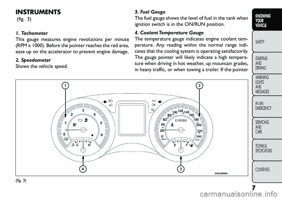
INSTRUMENTS(fig. 3)
1. Tachometer
This gauge measures engine revolutions per minute
(RPM x 1000). Before the pointer reaches the red area,
ease up on the accelerator to prevent engine damage.
2. Speedometer
Shows the vehicle speed. 3. Fuel Gauge
The fuel gauge shows the level of fuel in the tank when
ignition switch is in the ON/RUN position.
4. Coolant Temperature Gauge
The temperature gauge indicates engine coolant tem-
perature. Any reading within the normal range indi-
cates that the cooling system is operating satisfactorily.
The gauge pointer will likely indicate a high tempera-
ture when driving in hot weather, up mountain grades,
in heavy traffic, or when towing a trailer. If the pointer(fig. 3)
7
KNOWING
YOUR
VEHICLE
SAFETY
S
TARTING
AND
DRIVING
WARNING
LIGHTS
AND
MESSAGES
IN AN
EMERGENCY
SERVICING
AND
CARETECHNICAL
SPECIFICATIONSCONTENTS
Page 25 of 352
STEERING WHEEL LOCK
Your vehicle may be equipped with a passive electronic
steering wheel lock. This lock prevents steering the
vehicle without the ignition key. The steering wheel
lock has six positions (one every 60 degrees). If the
steering wheel is moved to one of these six position
with the key in the off positions, the steering wheel will
lock.
TO MANUALLY LOCK THE STEERING
WHEEL
With the engine running, rotate the steering wheel
one-half revolution, turn off the engine and remove the
key. Turn the steering wheel slightly in either direction
until the lock engages.
TO RELEASE THE STEERING WHEEL LOCK
Cycle the ignition and start the engine.
NOTE:If you turned the wheel to the right to engage
the lock, you must turn the wheel slightly to the right
to disengage it. If you turned the wheel to the left to
engage the lock, turn the wheel slightly to the left to
disengage it. ELECTRONIC VEHICLE
INFORMATION CENTER (EVIC)
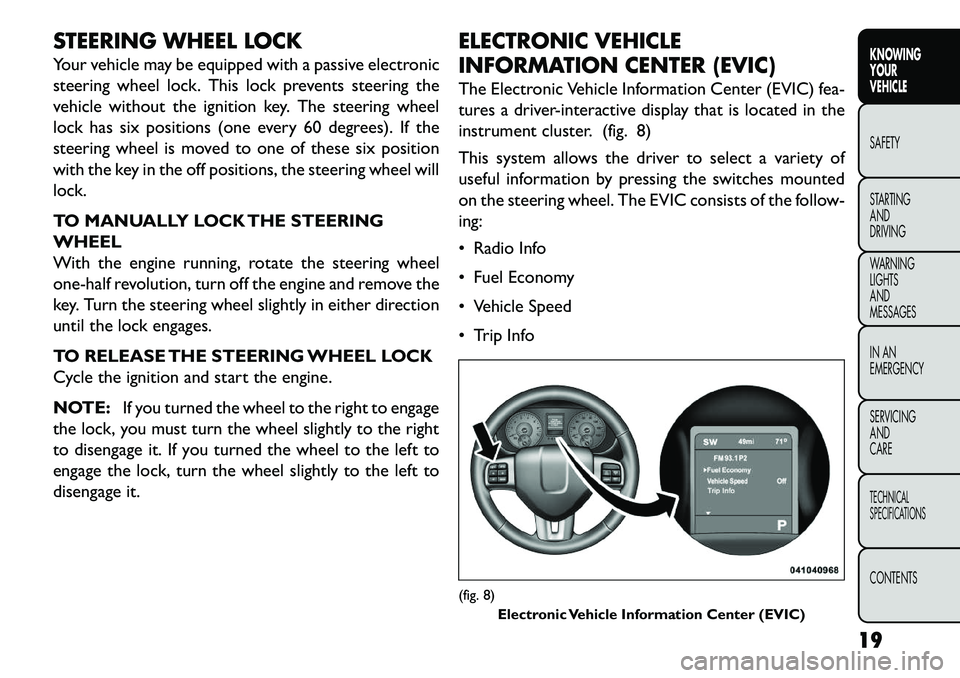
The Electronic Vehicle Information Center (EVIC) fea-
tures a driver-interactive display that is located in the
instrument cluster. (fig. 8)
This system allows the driver to select a variety of
useful information by pressing the switches mounted
on the steering wheel. The EVIC consists of the follow-
ing:
Radio Info
Fuel Economy
Vehicle Speed
Trip Info
(fig. 8)
Electronic Vehicle Information Center (EVIC)
19
KNOWING
YOUR
VEHICLE
SAFETY
S
TARTING
AND
DRIVING
WARNING
LIGHTS
AND
MESSAGES
IN AN
EMERGENCY
SERVICING
AND
CARETECHNICAL
SPECIFICATIONSCONTENTS
Page 26 of 352
Tire Pressure
Vehicle Information
Warning Message Displays
Turn Menu OFF
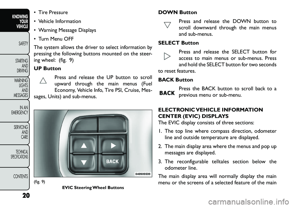
The system allows the driver to select information by
pressing the following buttons mounted on the steer-
ing wheel: (fig. 9)
UP ButtonPress and release the UP button to scroll
upward through the main menus (Fuel
Economy, Vehicle Info, Tire PSI, Cruise, Mes-
sages, Units) and sub-menus. DOWN Button
Press and release the DOWN button to
scroll downward through the main menus
and sub-menus.
SELECT Button Press and release the SELECT button for
access to main menus or sub-menus. Press
and hold the SELECT button for two seconds
to reset features.
BACK Button
Press the BACK button to scroll back to a
previous menu or sub-menu.
ELECTRONIC VEHICLE INFORMATION
CENTER (EVIC) DISPLAYS
The EVIC display consists of three sections:
1. The top line where compass direction, odometer line and outside temperature are displayed.
2. The main display area where the menus and pop up messages are displayed.
3. The reconfigurable telltales section below the odometer line.
The main display area will normally display the main
menu or the screens of a selected feature of the main(fig. 9) EVIC Steering Wheel Buttons
20
KNOWINGYOUR
VEHICLE
SAFETY
S
TARTING AND
DRIVING
WARNING LIGHTSAND
MESSAGES
IN AN
EMERGENCY
SERVICING AND
CARETECHNICAL
SPECIFICATIONSCONTENTS
Page 28 of 352
Left/Right Front Door Ajar (one or more doorsopen, with a single chime if speed is above 1.6 km/h)
Left/Right Rear Door Ajar (one or more doors open, with a single chime if speed is above 1.6 km/h)
Door(s) Ajar (with a single chime if vehicle is in motion)
Liftgate Ajar (with a single chime)
Low Washer Fluid (with a single chime)
Ignition or Accessory On
Vehicle Not in Park (for versions/markets, where provided)
Key Left Vehicle
Key Not Detected
Low Tire Pressure (with a single chime). Refer to information on “Tire Pressure” and “Tire Pressure
Monitor” in “Starting And Operating”.
Service TPM System (with a single chime). Refer to information on “Tire Pressure Monitor” in “Starting
And Operating”.
Check Gascap (refer to “Adding Fuel” in “Technical Specifications”)
Oil Change Required (with a single chime) Check Gascap (refer to “Adding Fuel” in “Starting
And Operating”)
Oil Change Due (with a single chime)
Exhaust System — Regeneration Required Now. Under conditions of exclusive short duration and
low speed driving and low speed driving cycles, the
engine and exhaust after-treatment system may
never reach the conditions required to remove the
trapped PM. If this occurs the “Exhaust System Re-
generation Required Now” message will be displayed
on the EVIC. By driving your vehicle at highway
speeds for as little as 30 minutes, you can remedy the
condition in the particulate filter system by allowing
the trapped PM to be removed to restore the system
to normal operating condition.
Exhaust Service Required — See Dealer Now. The engine will be de-rated to prevent permanent dam-
age to the after-treatment system. If this condition
occurs, it is necessary to have your vehicle serviced
by your local authorized dealer.
22
KNOWING YOUR
VEHICLE
SAFETY
S
TARTING AND
DRIVING
WARNING LIGHTSAND
MESSAGES
IN AN
EMERGENCY
SERVICING AND
CARETECHNICAL
SPECIFICATIONSCONTENTS
Page 29 of 352
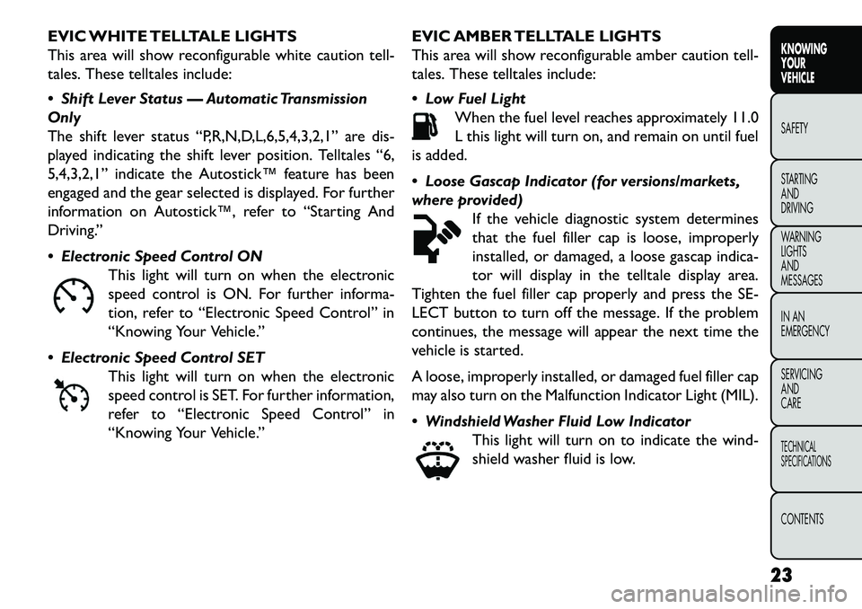
EVIC WHITE TELLTALE LIGHTS
This area will show reconfigurable white caution tell-
tales. These telltales include:
Shift Lever Status — Automatic Transmission
Only
The shift lever status “P,R,N,D,L,6,5,4,3,2,1” are dis-
played indicating the shift lever position. Telltales “6,
5,4,3,2,1” indicate the Autostick™ feature has been
engaged and the gear selected is displayed. For further
information on Autostick™, refer to “Starting And
Driving.”
Electronic Speed Control ONThis light will turn on when the electronic
speed control is ON. For further informa-
tion, refer to “Electronic Speed Control” in
“Knowing Your Vehicle.”
Electronic Speed Control SET This light will turn on when the electronic
speed control is SET. For further information,
refer to “Electronic Speed Control” in
“Knowing Your Vehicle.” EVIC AMBER TELLTALE LIGHTS
This area will show reconfigurable amber caution tell-
tales. These telltales include:
Low Fuel Light
When the fuel level reaches approximately 11.0
L this light will turn on, and remain on until fuel
is added.
Loose Gascap Indicator (for versions/markets,
where provided) If the vehicle diagnostic system determines
that the fuel filler cap is loose, improperly
installed, or damaged, a loose gascap indica-
tor will display in the telltale display area.
Tighten the fuel filler cap properly and press the SE-
LECT button to turn off the message. If the problem
continues, the message will appear the next time the
vehicle is started.
A loose, improperly installed, or damaged fuel filler cap
may also turn on the Malfunction Indicator Light (MIL).
Windshield Washer Fluid Low Indicator This light will turn on to indicate the wind-
shield washer fluid is low.
23KNOWING
YOUR
VEHICLE
SAFETY
S
TARTING
AND
DRIVING
WARNING
LIGHTS
AND
MESSAGES
IN AN
EMERGENCY
SERVICING
AND
CARETECHNICAL
SPECIFICATIONSCONTENTS
Page 32 of 352
FUEL ECONOMY
Press and release the UP or DOWN button until “Fuel
Economy” displays highlighted in the EVIC and press
the SELECT button. The following Fuel Economy func-
tions will display in the EVIC:
Average Fuel Economy
Distance To Empty (DTE)
L/100km
Average Fuel Economy
Shows the average fuel economy since the last reset.
When the fuel economy is reset, the display will read
“RESET” or show dashes for two seconds. Then, the
history information will be erased, and the averaging
will continue from the last fuel average reading before
the reset.
Distance To Empty (DTE)
Shows the estimated distance that can be traveled with
the fuel remaining in the tank. This estimated distance
is determined by a weighted average of the instanta-
neous and average fuel economy, according to the
current fuel tank level. DTE cannot be reset through
the SELECT button.
NOTE:Significant changes in driving style or vehicle
loading will greatly affect the actual drivable distance of
the vehicle, regardless of the DTE displayed value. When the DTE value is less than 48 km estimated
driving distance, the DTE display will change to a
“LOW FUEL” message. This display will continue until
the vehicle runs out of fuel. Adding a significant amount
of fuel to the vehicle will turn off the “LOW FUEL”
message and a new DTE value will display.
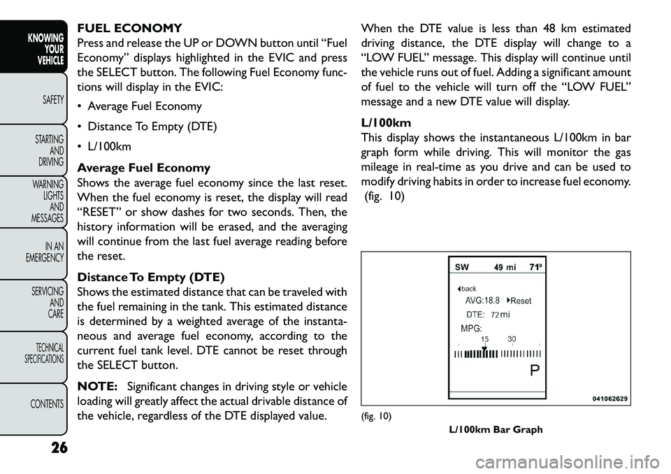
L/100km
This display shows the instantaneous L/100km in bar
graph form while driving. This will monitor the gas
mileage in real-time as you drive and can be used to
modify driving habits in order to increase fuel economy.
(fig. 10)
(fig. 10) L/100km Bar Graph
26
KNOWING YOUR
VEHICLE
SAFETY
S
TARTING AND
DRIVING
WARNING LIGHTSAND
MESSAGES
IN AN
EMERGENCY
SERVICING AND
CARETECHNICAL
SPECIFICATIONSCONTENTS
Page 73 of 352
NOTE:BI-LEVEL mode is designed under comfort
conditions to provide cooler air out of the panel
outlets and warmer air from the floor outlets.
Floor Mode Air comes from the floor outlets. A slight
amount of air is directed through the defrost
and side window demister outlets.
Mix Mode Air comes from the floor, defrost and side win-
dow demist outlets. This mode works best in
cold or snowy conditions.
Defrost Mode Air comes from the windshield and side window
demist outlets. Use Defrost mode with maxi-
mum temperature settings for best windshield and side
window defrosting and defogging. When the defrost
mode is selected, the blower level may will increase.
13. Climate Control OFF Button
Press and release this button to turn the Climate
Control ON/OFF.
14. Driver Temperature Control Down Button
Provides the driver with independent temperature
control. Push the button for cooler temperature set-
tings. NOTE:
In Sync mode, this button will also automati-
cally adjust the passenger temperature setting at the
same time.
15. Driver Temperature Control Up Button
Provides the driver with independent temperature
control. Push the button for warmer temperature
settings.
NOTE: In Sync mode, this button will also automati-
cally adjust the passenger temperature setting at the
same time.
16. Temperature Control (Manual Temperature
Control Only)
Press the temperature soft-key to regulate the tem-
perature of the air inside the passenger compartment.
Moving the temperature bar into the red area, indicates
warmer temperatures. Moving the temperature bar
into the blue area indicates cooler temperatures.
CLIMATE CONTROL FUNCTIONS
A/C (Air Conditioning)
The Air Conditioning (A/C) button allows the opera-
tor to manually activate or deactivate the air condition-
ing system. When the air conditioning system is turned
on, cool dehumidified air will flow through the outlets
into the cabin. For improved fuel economy, press the
A/C button to turn off the air conditioning and manu-
ally adjust the blower and airflow mode settings. Also,
67KNOWING
YOUR
VEHICLE
SAFETY
S
TARTING
AND
DRIVING
WARNING
LIGHTS
AND
MESSAGES
IN AN
EMERGENCY
SERVICING
AND
CARETECHNICAL
SPECIFICATIONSCONTENTS
Page 132 of 352
TRAILER SWAY CONTROL (TSC)
TSC uses sensors in the vehicle to recognize an exces-
sively swaying trailer. TSC activates automatically once
the excessively swaying trailer is recognized. When
TSC is functioning, the “ESC Activation/Malfunction
Indicator Light” will flash, the engine power will be
reduced, and you will feel the brake being applied to
individual wheels in an attempt to stop the trailer from
swaying.
NOTE:The TSC is disabled when the ESC system is
in the “Partial Off ” mode.
WARNING!
TS
C cannot stop all trailers from
swaying. Always use caution when tow-
ing a trailer and follow the tongue weight recom-
mendations. Refer to “Trailer Towing” in “Starting
and Driving” for further information.
If TSC activates while towing a trailer, stop the
vehicle at the nearest safe location and adjust
the trailer load to eliminate the trailer sway.
Failure to follow these warnings can result in
an accident or serious personal injury. ONBOARD DIAGNOSTIC SYSTEM —
OBD II
Your vehicle is equipped with a sophisticated onboard
diagnostic system called OBD II. This system monitors
the performance of the emissions, engine, and auto-
matic transmission control systems. When these sys-
tems are operating properly, your vehicle will provide
excellent performance and fuel economy, as well as
engine emissions well within current government regu-
lations.
If any of these systems require service, the OBD II
system will turn on the “Malfunction Indicator Light”
(MIL). It will also store diagnostic codes and other
information to assist your service technician in making
repairs. Although your vehicle will usually be drivable
and not need towing, see your authorized dealer for
service as soon as possible.
126
KNOWING YOUR
VEHICLE
SAFETY
S
TARTING AND
DRIVING
WARNING LIGHTSAND
MESSAGES
IN AN
EMERGENCY
SERVICING AND
CARETECHNICAL
SPECIFICATIONSCONTENTS
Page 133 of 352
Prolonged driving with the MIL on
could cause further damage to the emis-
sion control system. It could also affect
fuel economy and drivability.The vehicle must be
serviced before any emissions tests can be per-
formed.
If the MIL is flashing while the engine is run-
ning, severe catalytic converter damage and
power loss will soon occur. Immediate service is
required.
LOOSE FUEL FILLER CAP MESSAGE (for
versions/markets, where provided)
If the vehicle diagnostic system determines that the
fuel filler cap is loose, improperly installed, or damaged,
a “Check Gascap” message will display in the Electronic
Vehicle Information Center (EVIC). If this occurs,
tighten the fuel filler cap properly and press the TRIP
ODOMETER button to turn off the message. If the
problem continues, the message will appear the next
time the vehicle is started.
A loose, improperly installed, or damaged fuel filler cap
may also turn on the MIL. POWER STEERING
The standard power steering system will give you good
vehicle response and increased ease of maneuverability
in tight spaces. The system will provide mechanical
steering capability if power assist is lost.
If for some reason the power assist is interrupted, it
will still be possible to steer your vehicle. Under these
conditions, you will observe a substantial increase in
steering effort, especially at very low vehicle speeds
and during parking maneuvers.
NOTE:
Increased noise levels at the end of the steering
wheel travel are considered normal and do not
indicate that there is a problem with the power
steering system.
Upon initial start-up in cold weather, the power steering pump may make noise for a short amount of
time. This is due to the cold, thick fluid in the
steering system. This noise should be considered
normal, and it does not in any way damage the
steering system.
127
KNOWING
YOUR
VEHICLE
SAFETY
STARTING
AND
DRIVING
WARNING
LIGHTS
AND
MESSAGES
IN AN
EMERGENCY
SERVICING
AND
CARETECHNICAL
SPECIFICATIONSCONTENTS
Page 136 of 352
The TPMS has been optimized for the
original equipment tires and wheels.
TPMS pressures and warning have been
established for the tire size equipped on your
vehicle. Undesirable system operation or sensor
damage may result when using replacement
equipment that is not of the same size, type,
and/or style.Aftermarket wheels can cause sensor
damage. Do not use aftermarket tire sealants or
balance beads if your vehicle is equipped with a
TPMS, as damage to the sensors may result .
After inspecting or adjusting the tire pressure,
always reinstall the valve stem cap.This will pre-
vent moisture and dirt from entering the valve
stem, which could damage theTire Pressure Moni-
toring Sensor.
NOTE:
The TPMS is not intended to replace normal tire care and maintenance, or to provide warning of a tire
failure or condition.
The TPMS should not be used as a tire pressure gauge while adjusting your tire pressure.
Driving on a significantly under-inflated tire causes the tire to overheat and can lead to tire failure.
Under-inflation also reduces fuel efficiency and tire tread life, and may affect the vehicle’s handling and
stopping ability.
The TPMS is not a substitute for proper tire mainte- nance, and it is the driver’s responsibility to maintain
correct tire pressure using an accurate tire pressure
gauge, even if under-inflation has not reached the
level to trigger illumination of the Tire Pressure
Monitoring Telltale Light.
Seasonal temperature changes will affect tire pres- sure, and the TPMS will monitor the actual tire
pressure in the tire.
BASE SYSTEM
The Tire Pressure Monitor System (TPMS) uses wire-
less technology with wheel rim mounted electronic
sensors to monitor tire pressure levels. Sensors,
mounted to each wheel as part of the valve stem,
transmit tire pressure readings to the receiver module.
NOTE: It is particularly important for you to check
the tire pressure in all of the tires on your vehicle
monthly and to maintain the proper pressure.
The TPMS consists of the following components:
Receiver Module
Four Tire Pressure Monitoring Sensors
Tire Pressure Monitoring Telltale Light
130
KNOWING YOUR
VEHICLE
SAFETY
S
TARTING AND
DRIVING
WARNING LIGHTSAND
MESSAGES
IN AN
EMERGENCY
SERVICING AND
CARETECHNICAL
SPECIFICATIONSCONTENTS