inflation pressure FIAT FREEMONT 2013 Owner handbook (in English)
[x] Cancel search | Manufacturer: FIAT, Model Year: 2013, Model line: FREEMONT, Model: FIAT FREEMONT 2013Pages: 352, PDF Size: 5.22 MB
Page 135 of 352

TIRE PRESSURE MONITOR SYSTEM
(TPMS)
The Tire Pressure Monitor System (TPMS) will warn
the driver of a low tire pressure based on the vehicle
recommended cold placard pressure.
The tire pressure will vary with temperature by about
0.07 BAR for every 6.5°C. This means that when the
outside temperature decreases, the tire pressure will
decrease. Tire pressure should always be set based on
cold inflation tire pressure. This is defined as the tire
pressure after the vehicle has not been driven for at
least three hours, or driven less than 1.6 km after a
three hour period. The cold tire inflation pressure
must not exceed the maximum inflation pressure
molded into the tire sidewall. Refer to “Tires – General
Information” in “Technical Specifications” for informa-
tion on how to properly inflate the vehicle’s tires. The
tire pressure will also increase as the vehicle is driven.
This is normal and there should be no adjustment for
this increased pressure.The TPMS will warn the driver of a low tire pressure if
the tire pressure falls below the low-pressure warning
limit for any reason, including low temperature effects
and natural pressure loss through the tire.
The TPMS will continue to warn the driver of low tire
pressure as long as the condition exists, and will not
turn off until the tire pressure is at or above the
recommended cold placard pressure. Once the low
tire pressure warning (Tire Pressure Monitoring Tell-
tale Light) illuminates, you must increase the tire pres-
sure to the recommended cold placard pressure in
order for the Tire Pressure Monitoring Telltale Light to
turn off. The system will automatically update and the
Tire Pressure Monitoring Telltale Light will turn off
once the system receives the updated tire pressures.
The vehicle may need to be driven for up to 20 minutes
above 25 km/h in order for the TPMS to receive this
information.
129
KNOWING
YOUR
VEHICLE
SAFETY
STARTING
AND
DRIVING
WARNING
LIGHTS
AND
MESSAGES
IN AN
EMERGENCY
SERVICING
AND
CARETECHNICAL
SPECIFICATIONSCONTENTS
Page 136 of 352
The TPMS has been optimized for the
original equipment tires and wheels.
TPMS pressures and warning have been
established for the tire size equipped on your
vehicle. Undesirable system operation or sensor
damage may result when using replacement
equipment that is not of the same size, type,
and/or style.Aftermarket wheels can cause sensor
damage. Do not use aftermarket tire sealants or
balance beads if your vehicle is equipped with a
TPMS, as damage to the sensors may result .
After inspecting or adjusting the tire pressure,
always reinstall the valve stem cap.This will pre-
vent moisture and dirt from entering the valve
stem, which could damage theTire Pressure Moni-
toring Sensor.
NOTE:
The TPMS is not intended to replace normal tire care and maintenance, or to provide warning of a tire
failure or condition.
The TPMS should not be used as a tire pressure gauge while adjusting your tire pressure.
Driving on a significantly under-inflated tire causes the tire to overheat and can lead to tire failure.
Under-inflation also reduces fuel efficiency and tire tread life, and may affect the vehicle’s handling and
stopping ability.
The TPMS is not a substitute for proper tire mainte- nance, and it is the driver’s responsibility to maintain
correct tire pressure using an accurate tire pressure
gauge, even if under-inflation has not reached the
level to trigger illumination of the Tire Pressure
Monitoring Telltale Light.
Seasonal temperature changes will affect tire pres- sure, and the TPMS will monitor the actual tire
pressure in the tire.
BASE SYSTEM
The Tire Pressure Monitor System (TPMS) uses wire-
less technology with wheel rim mounted electronic
sensors to monitor tire pressure levels. Sensors,
mounted to each wheel as part of the valve stem,
transmit tire pressure readings to the receiver module.
NOTE: It is particularly important for you to check
the tire pressure in all of the tires on your vehicle
monthly and to maintain the proper pressure.
The TPMS consists of the following components:
Receiver Module
Four Tire Pressure Monitoring Sensors
Tire Pressure Monitoring Telltale Light
130
KNOWING YOUR
VEHICLE
SAFETY
S
TARTING AND
DRIVING
WARNING LIGHTSAND
MESSAGES
IN AN
EMERGENCY
SERVICING AND
CARETECHNICAL
SPECIFICATIONSCONTENTS
Page 137 of 352
Tire Pressure Monitoring Low Pressure
WarningsThe Tire Pressure Monitoring Telltale Light will
illuminate in the instrument cluster and a chime
will sound when tire pressure is low in one or more of
the four active road tires. Should this occur, you should
stop as soon as possible, check the inflation pressure of
each tire on your vehicle, and inflate each tire to the
vehicle’s recommended cold placard pressure value.
Once the system receives the updated tire pressures,
the system will automatically update and the Tire
Pressure Monitoring Telltale Light will turn off. The
vehicle may need to be driven for up to 20 minutes
above 25 km/h in order for the TPMS to receive this
information. Check TPMS Warning
When a system fault is detected, the Tire Pressure
Monitoring Telltale Light will flash on and off for 75
seconds and then remain on solid. The system fault will
also sound a chime. If the ignition switch is cycled, this
sequence will repeat, providing the system fault still
exists. The Tire Pressure Monitoring Telltale Light will
turn off when the fault condition no longer exists. A
system fault can occur due to any of the following:
1. Jamming due to electronic devices or driving next to
facilities emitting the same Radio Frequencies as the
TPMS sensors.
2. Installing some form of aftermarket window tinting that affects radio wave signals.
3. Lots of snow or ice around the wheels or wheel housings.
4. Using tire chains on the vehicle.
5. Using wheels/tires not equipped with TPMS sen- sors.
131KNOWING
YOUR
VEHICLE
SAFETY
S
TARTING
AND
DRIVING
WARNING
LIGHTS
AND
MESSAGES
IN AN
EMERGENCY
SERVICING
AND
CARETECHNICAL
SPECIFICATIONSCONTENTS
Page 236 of 352
WARNING!
Improper towing can lead to an injury
ac
cident . Follow these guidelines to
make your trailer towing as safe as possible:
Make certain that the load is secured in the trailer
and that it will not shift during travel.When trailering
cargo that is not fully secured, dynamic load shifts can
occur that may be difficult for the driver to control.
You could lose control of your vehicle and have an
accident .
All trailer hitches should be professionally
installed on your vehicle.
When hauling cargo or towing a trailer, do not
overload your vehicle or trailer. Overloading can
cause a loss of control, poor performance, or
damage to brakes, axle, engine, transmission,
steering, suspension, chassis structure, or tires.
Safety chains must always be used between
your vehicle and trailer. Always connect the
chains to the frame or hook retainers of the
vehicle hitch. Cross the chains under the trailer
tongue and allow enough slack for turning cor-
ners.
(Continued)(Continued)
Vehicles with trailers should not be parked on
a grade. When parking, apply the parking brake
on the tow vehicle. Always, block or "chock" the
trailer wheels.
GCWR must not be exceeded.
Total weight must be distributed between the
tow vehicle and the trailer such that the following
four ratings are not exceeded:
1. GVWR
2. GTW
3. GAWR
4. Tongue weight rating for the trailer hitch uti- lized.
Towing Requirements – Tires
– Do not attempt to tow a trailer while using a compact spare tire.
– Proper tire inflation pressures are essential for the safe and satisfactory operation of your vehicle. Refer
to “Tires – General Information” in “Technical Speci-
fications” for proper tire inflation procedures.
– Check the trailer tires for proper tire inflation pres- sures before trailer usage.
230
KNOWING YOUR
VEHICLE
SAFETY
STARTING AND
DRIVING
WARNING LIGHTSAND
MESSA
GES
IN AN
EMERGENCY
SERVICING AND
CARETECHNICAL
SPECIFICATIONSCONTENTS
Page 247 of 352
8. Park/Headlight ON IndicatorThis indicator will illuminate when the park
lights or headlights are turned on. (Refer to
“Lights” in “Knowing Your Vehicle” for fur-
ther information).
9. Tire Pressure Monitoring Telltale Light Each tire, including the spare (if provided),
should be checked monthly when cold and
inflated to the inflation pressure recom-
mended by the vehicle manufacturer on the
vehicle placard or tire inflation pressure label.
As an added safety feature, your vehicle has been
equipped with a tire pressure monitoring system
(TPMS) that illuminates a low tire pressure telltale
when one or more of your tires is significantly under-
inflated. Accordingly, when the low tire pressure tell-
tale light illuminates, you should stop and check your
tires as soon as possible, and inflate them to the proper
pressure. Driving on a significantly under-inflated tire
causes the tire to overheat and can lead to tire failure.
Under-inflation also reduces fuel efficiency and tire
tread life, and may affect the vehicle’s handling and
stopping ability. Please note that the TPMS is not a substitute for
proper tire maintenance, and it is the driver’s respon-
sibility to maintain correct tire pressure, even if under-
inflation has not reached the level to trigger illumina-
tion of the TPMS low tire pressure telltale.
Your vehicle has also been equipped with a TPMS
malfunction indicator to indicate when the system is
not operating properly. The TPMS malfunction indica-
tor is combined with the low tire pressure telltale.
When the system detects a malfunction, the telltale
will flash for approximately one minute and then re-
main continuously illuminated. This sequence will con-
tinue upon subsequent vehicle start-ups as long as the
malfunction exists. When the malfunction indicator is
illuminated, the system may not be able to detect or
signal low tire pressure as intended. TPMS malfunctions
may occur for a variety of reasons, including the instal-
lation of replacement or alternate tires or wheels on
the vehicle that prevent the TPMS from functioning
properly. Always check the TPMS malfunction telltale
light after replacing one or more tires or wheels on
your vehicle to ensure that the replacement or alter-
nate tires and wheels allow the TPMS to continue to
function properly.
241KNOWING
YOUR
VEHICLE
SAFETY
STARTING
AND
DRIVING
WARNING
LIGHTS
AND
MESSA
GES
IN AN
EMERGENC Y
SERVICING
AND
CARETECHNICAL
SPECIFICATIONSCONTENTS
Page 248 of 352
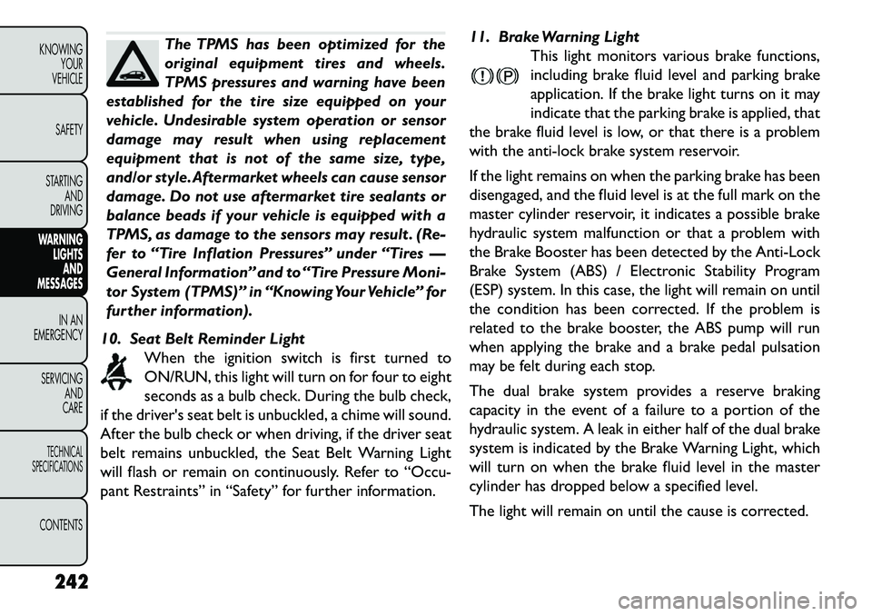
The TPMS has been optimized for the
original equipment tires and wheels.
TPMS pressures and warning have been
established for the tire size equipped on your
vehicle. Undesirable system operation or sensor
damage may result when using replacement
equipment that is not of the same size, type,
and/or style.Aftermarket wheels can cause sensor
damage. Do not use aftermarket tire sealants or
balance beads if your vehicle is equipped with a
TPMS, as damage to the sensors may result . (Re-
fer to “Tire Inflation Pressures” under “Tires —
General Information” and to “Tire Pressure Moni-
tor System (TPMS)” in “Knowing Your Vehicle” for
further information).
10. Seat Belt Reminder Light When the ignition switch is first turned to
ON/RUN, this light will turn on for four to eight
seconds as a bulb check. During the bulb check,
if the driver's seat belt is unbuckled, a chime will sound.
After the bulb check or when driving, if the driver seat
belt remains unbuckled, the Seat Belt Warning Light
will flash or remain on continuously. Refer to “Occu-
pant Restraints” in “Safety” for further information. 11. Brake Warning Light
This light monitors various brake functions,
including brake fluid level and parking brake
application. If the brake light turns on it may
indicate that the parking brake is applied, that
the brake fluid level is low, or that there is a problem
with the anti-lock brake system reservoir.
If the light remains on when the parking brake has been
disengaged, and the fluid level is at the full mark on the
master cylinder reservoir, it indicates a possible brake
hydraulic system malfunction or that a problem with
the Brake Booster has been detected by the Anti-Lock
Brake System (ABS) / Electronic Stability Program
(ESP) system. In this case, the light will remain on until
the condition has been corrected. If the problem is
related to the brake booster, the ABS pump will run
when applying the brake and a brake pedal pulsation
may be felt during each stop.
The dual brake system provides a reserve braking
capacity in the event of a failure to a portion of the
hydraulic system. A leak in either half of the dual brake
system is indicated by the Brake Warning Light, which
will turn on when the brake fluid level in the master
cylinder has dropped below a specified level.
The light will remain on until the cause is corrected.
242
KNOWING YOUR
VEHICLE
SAFETY
STARTING AND
DRIVING
WARNING LIGHTSAND
MESSA
GES
IN AN
EMERGENC
Y
SERVICING AND
CARETECHNICAL
SPECIFICATIONSCONTENTS
Page 265 of 352
(Continued)
A loose TIREFIT kit thrown forward in a colli-
sion or hard stop could endanger the occupants
of the vehicle. Always stow the TIREFIT kit in the
place provided. Failure to follow these warnings
can result in injuries that are serious or fatal to
you, your passengers, and others around you.
Take care not to allow the contents of TIREFIT
to come in contact with hair, eyes, or clothing.
TIREFIT is harmful if inhaled, swallowed, or ab-
sorbed through the skin: It causes skin, eye, and
respiratory irritation. Flush immediately with
plenty of water if there is any contact with eyes
or skin. Change clothing as soon as possible, if
there is any contact with clothing.
TIREFIT Sealant solution contains latex. In
case of allergic reaction or rash, consult a physi-
cian immediately. Keep TIREFIT out of reach of
children. If swallowed, rinse mouth immediately
with plenty of water and drink plenty of water.
Do not induce vomiting! Consult a physician im-
mediately.
Use the gloves provided in the Accessory Stor-
age Compartment (located on the bottom of the
air pump) when operating the TIREFIT kit . Sealing A Tire With TIREFIT
If the sealant (white fluid) does flow
through the
Sealant Hose (6):
1. Continue to operate the pump until sealant is no longer flowing through hose (typically takes 30 - 70
seconds). As the sealant flows through the Sealant
Hose (6), the Pressure Gauge (3) can read as high as
5 Bar. The Pressure Gauge (3) will decrease quickly
from approximately 5 Bar to the actual tire pressure
when the Sealant Bottle (1) is empty.
2. The pump will start to inject air into the tire immediately after the Sealant Bottle (1) is empty.
Continue to operate the pump and inflate the tire
to the pressure indicated on the tire pressure label
on the driver-side latch pillar (recommended pres-
sure). Check the tire pressure by looking at the
Pressure Gauge (3).
If the tire does not inflate to at least 1.8 Bar
pressure within 15 minutes:
The tire is too badly damaged. Do not attempt to drive the vehicle further. Call for assistance.
NOTE: If the tire becomes over-inflated, press the
Deflation Button to reduce the tire pressure to the
recommended inflation pressure before continuing.
259
KNOWING
YOUR
VEHICLE
SAFETY
STARTING
AND
DRIVING
WARNING
LIGHTS
AND
MESSAGES
IN AN
EMERGENCY
SERVICING
AND
C ARETECHNICAL
SPECIFICATIONSCONTENTS
Page 268 of 352
If the tire does not inflate to at least 26 (1.8 Bar)
pressure within 15 minutes:
The tire is too badly damaged. Do not attempt todrive the vehicle further. Call for assistance.
NOTE: If the tire becomes over-inflated, press the
Deflation Button to reduce the tire pressure to the
recommended inflation pressure before continuing.
If the tire inflates to the recommended pres-
sure or is at least 26 (1.8 Bar) pressure within 15
minutes:
1. Press the Power Button (4) to turn off the TIREFIT
kit.
2. Remove the Speed Limit sticker from the top of the Sealant Bottle (1) and place the sticker on the
instrument panel.
3. Immediately disconnect the Sealant Hose (6) from the valve stem, reinstall the cap on the fitting at the
end of the hose, and place the TIREFIT kit in the
vehicle storage location. Quickly proceed to (D)
“Drive Vehicle”.
The metal end fitting from Power Plug
(8) may get hot after use, so it should be
handled carefully.
Failure to reinstall the cap on the fitting at the
end of the Sealant Hose (6) can result in sealant
contacting your skin, clothing, and the vehicle’s
interior. It can also result in sealant contacting
internalTIREFIT kit components which may cause
permanent damage to the kit .
(D) Drive Vehicle:
Immediately after injecting sealant and inflating the tire,
drive the vehicle 8 km or 10 minutes to ensure distri-
bution of the TIREFIT Sealant within the tire. Do not
exceed 88 km/h.
WARNING!
TIREFIT is not a permanent flat tire
re
pair. Have the tire inspected and re-
paired or replaced after using TIREFIT. Do not
exceed 88 km/h until the tire is repaired or
replaced. Failure to follow this warning can result
in injuries that are serious or fatal to you, your
passengers, and others around you.
262
KNOWING YOUR
VEHICLE
SAFETY
STARTING AND
DRIVING
WARNING LIGHTSAND
MESSAGES
IN AN
EMERGENC
Y
SERVICING AND
C
ARETECHNICAL
SPECIFICATIONSCONTENTS
Page 269 of 352
(E) After Driving:
Pull over to a safe location. Refer to “Whenever You
Stop to Use TIREFIT” before continuing.
1. Turn the Mode Select Knob (5) to the Air Modeposition.
2. Uncoil the power plug and insert the plug into the vehicle's 12 Volt power outlet.
3. Uncoil the Air Pump Hose (7) (black in color) and screw the fitting at the end of hose (7) onto the
valve stem.
4. Check the pressure in the tire by reading the Pres- sure Gauge (3).
If tire pressure is less than 1.3 Bar, the tire is too
badly damaged. Do not attempt to drive the vehicle
further. Call for assistance.
If the tire pressure is 1.3 bar or higher:
1. Press the Power Button (4) to turn on TIREFIT and inflate the tire to the pressure indicated on the tire
and loading information label on the driver-side
door opening.
NOTE: If the tire becomes over-inflated, press the
Deflation Button to reduce the tire pressure to the
recommended inflation pressure before continuing. 2. Disconnect the TIREFIT kit from the valve stem,
reinstall the cap on the valve stem and unplug from
12 Volt outlet.
3. Place the TIREFIT kit in its proper storage area in the vehicle.
4. Have the tire inspected and repaired or replaced at the earliest opportunity at an authorized dealer or
tire service center.
5. Replace the Sealant Bottle (1) and Sealant Hose (6) assembly at your authorized dealer as soon as pos-
sible. Refer to “(F) Sealant Bottle and Hose Replace-
ment.”
NOTE: When having the tire serviced, advise the
authorized dealer or service center that the tire has
been sealed using the TIREFIT service kit.
(F) Sealant Bottle And Hose Replacement:
1. Uncoil the Sealant Hose (6) (clear in color).
2. Locate the round Sealant Bottle release button in the recessed area under the sealant bottle.
3. Press the Sealant Bottle release button. The Sealant Bottle (1) will pop up. Remove the bottle and
dispose of it accordingly.
4. Clean any remaining sealant from the TIREFIT hous- ing.
263
KNOWING
YOUR
VEHICLE
SAFETY
STARTING
AND
DRIVING
WARNING
LIGHTS
AND
MESSAGES
IN AN
EMERGENCY
SERVICING
AND
C ARETECHNICAL
SPECIFICATIONSCONTENTS
Page 292 of 352
Periodic Checks
Every1,000 km or before long journeys, check and, if
necessary, restore:
engine coolant;
brake fluid;
windshield washer fluid level;
power steering fluid;
tire inflation pressure and condition;
operation of lighting system (headlights, direction indicators, hazard warning lights, etc.);
operation of windshield washer/wiper system and positioning/wear of windshield/rear window wiper
blades.
Every 3,000 km, check and top up, if required, the
engine oil level.
Heavy-Duty Use Of The Car
If the car is used mainly under one of the following
conditions:
towing a trailer or caravan;
dusty roads;
short, repeated journeys (less than 7-8 km) at sub- zero outside temperatures; engine often idling or driving long distances at low
speeds or long periods of idleness.
You should perform the following inspections more
frequently than shown on the Scheduled Servicing Plan:
check front disc brake pad conditions and wear;
check cleanliness of hood and trunk locks, cleanli- ness and lubrication of linkage;
visually inspect conditions of: engine, transmission, pipes and hoses (exhaust - fuel system - brakes) and
rubber elements (boots - sleeves - bushes - etc.);
check battery charge and battery fluid level (electro- lyte);
visually inspect condition of the accessory drive belts;
check and, if necessary, change engine oil and replace oil filter;
check and, if necessary, replace pollen filter;
check and, if necessary, replace air cleaner.
MAINTENANCE SCHEDULE — DIESEL
ENGINE
Required Maintenance Intervals
Refer to the Maintenance Schedules on the following
pages for the required maintenance intervals.
286
KNOWING YOUR
VEHICLE
SAFETY
STARTING AND
DRIVING
WARNING LIGHTSAND
MESSAGES
IN AN
EMERGENCY
SERVICING AND
C
ARETECHNICAL
SPECIFICATIONSCONTENTS