sensor FIAT FREEMONT 2016 1.G User Guide
[x] Cancel search | Manufacturer: FIAT, Model Year: 2016, Model line: FREEMONT, Model: FIAT FREEMONT 2016 1.GPages: 412, PDF Size: 3.36 MB
Page 162 of 412
Tire Pressure Monitoring Low Pressure
WarningsThe Tire Pressure Monitoring Telltale Light will
illuminate in the instrument cluster and a chime
will sound when tire pressure is low in one or more of
the four active road tires. In addition, the Electronic
Vehicle Information Center (EVIC) will display a
graphic showing the pressure values of each tire with
the low tire pressure values in a different color. An
"Inflate Tire to XXX" message will also be displayed.
Should this occur, you should stop as soon as possible
and inflate the tires with low pressure (those displayed
in a different color in the EVIC graphic) to the vehicle’s
recommended cold placard pressure value as shown in
the "Inflate Tire to XXX" message.
NOTE: When filling warm tires, the tire pressure may
need to be increased to an additional 0.3 BAR above
the recommended cold placard pressure in order to
turn the Tire Pressure Monitoring Telltale Light off.
Once the system receives the updated tire pressures,
the system will automatically update, the graphic dis-
play in the EVIC will return to the original color, and
the Tire Pressure Monitoring Telltale Light will turn off.
The vehicle may need to be driven for up to 20 minutes
above 25 km/h in order for the TPMS to receive this
information. ServiceTPMS Warning
When a system fault is detected, the Tire Pressure
Monitoring Telltale Light will flash on and off for 75
seconds and then remain on solid. The system fault will
also sound a chime. In addition, the EVIC will display a
"SERVICE TPM SYSTEM" message for a minimum of
five seconds and then display dashes (- -) in place of the
pressure value to indicate which sensor is not being
received.
If the ignition switch is cycled, this sequence will repeat,
providing the system fault still exists. If the system fault
no longer exists, the Tire Pressure Monitoring Telltale
Light will no longer flash, and the "SERVICE TPM
SYSTEM" message will no longer display, and a pressure
value will display in place of the dashes. A system fault
can occur due to any of the following:
1. Jamming due to electronic devices or driving next to
facilities emitting the same radio frequencies as the
TPMS sensors.
2. Installing some form of aftermarket window tinting that affects radio wave signals.
3. Lots of snow or ice around the wheels or wheel housings.
4. Using tire chains on the vehicle.
5.
Using wheels/tires not equipped with TPMS sensors.
156
KNOWING YOUR
VEHICLE
SAFETY
STAR
TINGAND
DRIVING
WARNING LIGHTSAND
MESSAGES
IN AN
EMERGENCY
SERVICINGAND CARE
TECHNICAL
SPECIFICATIONS
CONTENTS
Page 163 of 412
The EVIC will also display a "SERVICE TPM SYSTEM"
message for a minimum of five seconds when a system
fault related to an incorrect sensor location fault is
detected. In this case, the "SERVICE TPM SYSTEM"
message is then followed with a graphic display with
pressure values still shown. This indicates that the
pressure values are still being received from the TPM
sensors but they may not be located in the correct
vehicle position. The system still needs to be serviced
as long as the "SERVICE TPM SYSTEM" message is
displayed.
NOTE:
1. The compact spare tire does not have a tire pres-sure monitoring sensor. Therefore, the TPMS will
not monitor the pressure in the compact spare tire.
2. If you install the compact spare tire in place of a road tire that has a pressure below the low-pressure
warning limit, upon the next ignition switch cycle,
the TPMS Telltale Light will remain on and a chime
will sound. In addition, the graphic in the EVIC will
still display a different color pressure value. An
"Inflate Tire to XXX" message will also be displayed. 3. After driving the vehicle for up to 20 minutes above
25 km/h, the TPMS Telltale Light will flash on and off
for 75 seconds and then remain on solid. In addition,
the EVIC will display a "SERVICE TPM SYSTEM"
message for a minimum of five seconds and then
display dashes (- -) in place of the pressure value.
4. For each subsequent ignition switch cycle, a chime will sound, the TPMS Telltale Light will flash on and
off for 75 seconds and then remain on solid, and the
EVIC will display a "SERVICE TPM SYSTEM" mes-
sage for a minimum of five seconds and then display
dashes (- -) in place of the pressure value.
5. Once you repair or replace the original road tire and reinstall it on the vehicle in place of the compact
spare, the TPMS will update automatically. In addi-
tion, the TPMS Telltale Light will turn off and the
graphic in the EVIC will display a new pressure value
instead of dashes (- -), as long as no tire pressure is
below the low-pressure warning limit in any of the
four active road tires. The vehicle may need to be
driven for up to 20 minutes above 25 km/h in order
for the TPMS to receive this information.
157
KNOWING
YOUR
VEHICLE
SAFETY
STAR
TING
AND
DRIVING
WARNING
LIGHTS
AND
MESSAGES
IN AN
EMERGENCY
SERVICING
AND CARE
TECHNICAL
SPECIFICATIONS
CONTENTS
Page 164 of 412
TPMS Deactivation And Reactivation
The TPMS can be deactivated if replacing all four wheel
and tire assemblies (road tires) with wheel and tire
assemblies that do not have TPMS Sensors, such as
when installing winter wheel and tire assemblies on
your vehicle.
To deactivate the TPMS, first, replace all four wheel and
tire assemblies (road tires) with those not equipped
with TPM Sensors. Then, drive the vehicle for 20
minutes above 25 km/h. The TPMS will chime and the
Tire Pressure Monitoring Telltale Light will flash on and
off for 75 seconds and then remain on solid. In addition,
the Electronic Vehicle Information Center (EVIC) will
display a “SERVICE TPM SYSTEM” text message, and
the graphic will display “- -“ in place of four tire
pressure values. Upon the next ignition switch cycle,
the TPMS will no longer chime or turn on the Tire
Pressure Monitoring Telltale Light, or display the text
message in the EVIC. However, the graphic will still
display “- -.“To reactivate the TPMS, first, replace all four wheel and
tire assemblies (road tires) with those equipped with
TPM Sensors. Then, drive the vehicle for up to 20
minutes above 25 km/h. The TPMS will chime, the Tire
Pressure Monitoring Telltale Light will flash on and off
for 75 seconds, the EVIC will display a “SERVICE TPM
SYSTEM” text message, and the graphic will display tire
pressure values to show that the TPMS is receiving
sensor data.
GENERAL INFORMATION
Transmitter and receivers operate on a carrier fre-
quency of 433.92 MHz as required by EEC regulations.
These devices must be certified to conform to specific
regulations in each individual country. Two sets of
regulations are involved: ETS (European Telecommuni-
cation Standard) 300–220, which most countries use,
and German BZT federal regulation 225Z125, which is
based on ETC 300–220 but has additional unique re-
quirements. Other defined requirements are noted in
ANNEX VI of COMMISSION DIRECTIVE 95/56/EC.
Operation is subject to the following two conditions:
• This device may not cause harmful interference.
• This device must accept any interference received,
including interference that may cause undesired op-
eration.
158
KNOWING YOUR
VEHICLE
SAFETY
STAR
TINGAND
DRIVING
WARNING LIGHTSAND
MESSAGES
IN AN
EMERGENCY
SERVICINGAND CARE
TECHNICAL
SPECIFICATIONS
CONTENTS
Page 165 of 412
REAR PARK ASSIST (for
versions/markets, where
provided)
The Rear Park Assist system provides visual and audible
indications of the distance between the rear fascia and
a detected obstacle when backing up, e.g. during a
parking maneuver. Refer to “Park Assist System Usage
Precautions” for limitations of this system and recom-
mendations.
Park Assist will retain the last system state (enabled or
disabled) from the last ignition cycle when the ignition
is changed to the ON/RUN position.
Park Assist can be active only when the shift lever is in
REVERSE. If Park Assist is enabled at this shift lever
position, the system will remain active until the vehicle
speed is increased to approximately 11 km/h or above.
The system will become active again if the vehicle
speed is decreased to speeds less than approximately
9 km/h.PARK ASSIST SENSORS
The four Park Assist sensors, located in the rear
fascia/bumper, monitor the area behind the vehicle that
is within the sensors’ field of view. The sensors can
detect obstacles from approximately 30 cm up to 200
cm from the rear fascia/bumper in the horizontal direc-
tion, depending on the location, type and orientation
of the obstacle.
PARK ASSIST WARNING DISPLAY
The Park Assist Warning screen will only be displayed if
Sound and Display is selected from the Uconnect®
System. Refer to “Uconnect® Settings” for further
information.
The Park Assist Warning screen is located within the
Electronic Vehicle Information Center (EVIC). It pro-
vides visual warnings to indicate the distance between
the rear fascia/bumper and the detected obstacle. Re-
fer to “Electronic Vehicle Information Center (EVIC)/
Settings” for further information.
159
KNOWING
YOUR
VEHICLE
SAFETY
STAR
TING
AND
DRIVING
WARNING
LIGHTS
AND
MESSAGES
IN AN
EMERGENCY
SERVICING
AND CARE
TECHNICAL
SPECIFICATIONS
CONTENTS
Page 169 of 412
If “CLEAN PARK ASSIST” appears in the Electronic
Vehicle Information Center (EVIC) make sure the
outer surface and the underside of the rear fascia/
bumper is clean and clear of snow, ice, mud, dirt or
other obstruction and then cycle the ignition. If the
message continues to appear see an authorized dealer.
If “SERVICE PARK ASSIST” or “SERVICE PARK ASSIST
SYSTEM” appears in the EVIC, see your authorized
dealer.
CLEANING THE PARK ASSIST SYSTEM
Clean the sensors with water, car wash soap and a soft
cloth. Do not use rough or hard cloths. Do not scratch
or poke the sensors. Otherwise, you could damage the
sensors.
PARK ASSIST SYSTEM USAGE
PRECAUTIONS
NOTE:
• Ensure that the rear bumper is free of snow, ice,mud, dirt and debris to keep the Park Assist system
operating properly.
• Jackhammers, large trucks, and other vibrations could affect the performance of Park Assist. • When you turn Park Assist off, the EVIC will display
“PARK ASSIST SYSTEM OFF.” Furthermore, once
you turn Park Assist off, it remains off until you turn
it on again, even if you cycle the ignition key.
• When you move the shift lever to the REVERSE position and Park Assist is turned off, the EVIC will
display the “PARK ASSIST SYSTEM OFF” message
for as long as the vehicle is in REVERSE.
• Clean the Park Assist sensors regularly, taking care not to scratch or damage them. The sensors must
not be covered with ice, snow, slush, mud, dirt or
debris. Failure to do so can result in the system not
working properly. The Park Assist system might not
detect an obstacle behind the fascia/bumper, or it
could provide a false indication that an obstacle is
behind the fascia/bumper.
• Ensure that the Park Assist system is turned OFF if objects such as bicycle carriers, trailer hitches, etc.,
are placed within 30 cm from the rear fascia/bumper
while driving the vehicle. Failure to do so can result in
the system misinterpreting a close object as a sensor
problem, causing the “SERVICE PARK ASSIST” mes-
sage to be displayed in the EVIC.
163
KNOWING
YOUR
VEHICLE
SAFETY
STAR
TING
AND
DRIVING
WARNING
LIGHTS
AND
MESSAGES
IN AN
EMERGENCY
SERVICING
AND CARE
TECHNICAL
SPECIFICATIONS
CONTENTS
Page 170 of 412
•Park Assist is only a parking aid and it is
unable to recognize every obstacle, in-
cluding small obstacles. Parking curbs
might be temporarily detected or not detected at
all. Obstacles located above or below the sensors
will not be detected when they are in close prox-
imity.
• The vehicle must be driven slowly when using
Park Assist in order to be able to stop in time when
an obstacle is detected. It is recommended that
the driver looks over his/her shoulder when using
Park Assist .
WARNING!
• Drivers must be careful when backing
up e
ven when using Park Assist . Always
check carefully behind your vehicle, look behind
you, and be sure to check for pedestrians, ani-
mals, other vehicles, obstructions, and blind spots
before backing up.You are responsible for safety
and must continue to pay attention to your sur-
roundings. Failure to do so can result in serious
injury or death.
(Continued)
WARNING! (Continued)
• Before using Park Assist , it is strongly recom-
mended that the ball mount and hitch ball as-
sembly is disconnected from the vehicle when the
vehicle is not used for towing. Failure to do so can
result in injury or damage to vehicles or obstacles
because the hitch ball will be much closer to the
obstacle than the rear fascia when the loud-
speaker sounds the continuous tone. Also, the
sensors could detect the ball mount and hitch ball
assembly, depending on its size and shape, giving
a false indication that an obstacle is behind the
vehicle.
164
KNOWING YOUR
VEHICLE
SAFETY
STAR
TINGAND
DRIVING
WARNING LIGHTSAND
MESSAGES
IN AN
EMERGENCY
SERVICINGAND CARE
TECHNICAL
SPECIFICATIONS
CONTENTS
Page 208 of 412
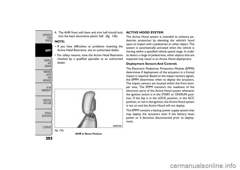
4. The AHR front soft foam and trim half should lockinto the back decorative plastic half. (fig. 136)
NOTE:
• If you have difficulties or problems resetting the Active Head Restraints, see an authorized dealer.
• For safety reasons, have the Active Head Restraints checked by a qualified specialist at an authorized
dealer. ACTIVE HOOD SYSTEM
The Active Hood system is intended to enhance pe-
destrian protection by elevating the vehicle’s hood
upon an impact with a pedestrian or other object. The
system is automatically activated when the vehicle is
moving within a specified vehicle speed range. In order
to detect a range of pedestrians, other objects that are
impacted may result in an Active Hood deployment.
Deployment Sensors And Controls
The Electronic Pedestrian Protection Module (EPPM)
determines if deployment of the actuators in a frontal
impact is required. Based on the impact sensors signals,
the EPPM determines when to deploy the actuators.
The impact sensors are located within the front bum-
per area. The EPPM monitors the readiness of the
electronic parts of the Active Hood system whenever
the ignition switch is in the START or ON/RUN posi-
tion. If the key is in the LOCK position, in the ACC
position, or not in the ignition, the Active Hood system
is not on and the Active Hood will not deploy.
The EPPM contains a backup power supply system that
may deploy the actuators even if the battery loses
power or it becomes disconnected prior to deploy-
ment.
(fig. 136)
AHR In Reset Position
202
KNOWINGYOUR
VEHICLE
SAFETY
STARTING AND
DRIVING
WARNING LIGHTSAND
MESSAGES
IN
AN
EMERGENCY
SERVICINGAND CARE
TECHNICAL
SPECIFICATIONS
CONTENTS
Page 211 of 412
SUPPLEMENTAL RESTRAINT SYSTEM
(SRS)
AIR BAG SYSTEM COMPONENTS
Your vehicle may be equipped with the following air bag
system components:
• Occupant Restraint Controller (ORC)
• Air Bag Warning Light
• Steering Wheel and Column
• Instrument Panel
• Knee Impact Bolsters
• Advanced Front Air Bags
• Supplemental Side Air Bags
• Front and Side Impact Sensors
• Seat Belt Pretensioners
• Seat Belt Buckle SwitchADVANCED FRONT AIR BAGS
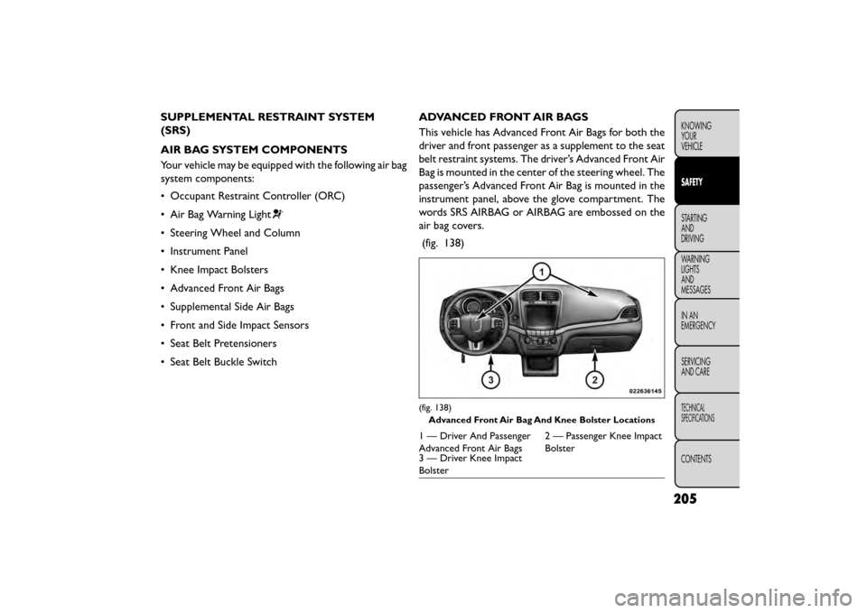
This vehicle has Advanced Front Air Bags for both the
driver and front passenger as a supplement to the seat
belt restraint systems. The driver’s Advanced Front Air
Bag is mounted in the center of the steering wheel. The
passenger’s Advanced Front Air Bag is mounted in the
instrument panel, above the glove compartment. The
words SRS AIRBAG or AIRBAG are embossed on the
air bag covers.
(fig. 138)
(fig. 138) Advanced Front Air Bag And Knee Bolster Locations
1 — Driver And Passenger
Advanced Front Air Bags 2 — Passenger Knee Impact
Bolster
3 — Driver Knee Impact
Bolster
205
KNOWING
YOUR
VEHICLE
SAFETY
STARTING
AND
DRIVING
WARNING
LIGHTS
AND
MESSAGES
IN
AN
EMERGENCY
SERVICING
AND CARE
TECHNICAL
SPECIFICATIONS
CONTENTS
Page 212 of 412
WARNING!
• Being too close to the steering wheel
or ins
trument panel during Advanced
Front Air Bag deployment could cause serious
injury, including death. Air bags need room to
inflate. Sit back, comfortably extending your
arms to reach the steering wheel or instrument
panel.
• Never place a rear-facing child restraint in
front of an air bag. A deploying Passenger Ad-
vanced Front Air Bag can cause death or serious
injury to a child 12 years or younger, including a
child in a rear-facing child restraint .
• Only use a rear-facing child restraint in a ve-
hicle with a rear seat .
ADVANCED FRONT AIR BAG FEATURES
The Advanced Front Air Bag system has multistage
driver and front passenger air bags. This system pro-
vides output appropriate to the severity and type of
collision as determined by the Occupant Restraint
Controller (ORC), which may receive information
from the front impact sensors or other system com-
ponents.
The first stage inflator is triggered immediately during
an impact that requires air bag deployment. A low energy output is used in less severe collisions. A higher
energy output is used for more severe collisions.
This vehicle may be equipped with a driver and/or front
passenger seat belt buckle switch that detects whether
the driver or front passenger seat belt is buckled. The
seat belt buckle switch may adjust the inflation rate of
the Advanced Front Air Bags.
WARNING!
• No objects should be placed over or
n ear
the air bag on the instrument panel
or steering wheel, because any such objects could
cause harm if the vehicle is in a collision severe
enough to cause the air bags to inflate.
• Do not put anything on or around the air bag
covers or attempt to open them manually. You
may damage the air bags and you could be
injured because the air bags may no longer be
functional. The protective covers for the air bag
cushions are designed to open only when the air
bags are inflating.
• Relying on the air bags alone could lead to
more severe injuries in a collision. The air bags
work with your seat belt to restrain you properly.
In some collisions, air bags won’t deploy at all.
Always wear your seat belts even though you
have air bags.
206
KNOWING YOUR
VEHICLE
SAFETY
STARTING AND
DRIVING
WARNING LIGHTSAND
MESSAGES
IN
AN
EMERGENCY
SERVICINGAND CARE
TECHNICAL
SPECIFICATIONS
CONTENTS
Page 213 of 412
ADVANCED FRONT AIR BAG OPERATION
Advanced Front Air Bags are designed to provide
additional protection by supplementing the seat belts.
Advanced Front Air Bags are not expected to reduce
the risk of injury in rear, side, or rollover collisions. The
Advanced Front Air Bags will not deploy in all frontal
collisions, including some that may produce substantial
vehicle damage — for example, some pole collisions,
truck underrides, and angle offset collisions.
On the other hand, depending on the type and location
of impact, Advanced Front Air Bags may deploy in
crashes with little vehicle front-end damage but that
produce a severe initial deceleration.
Because air bag sensors measure vehicle deceleration
over time, vehicle speed and damage by themselves are
not good indicators of whether or not an air bag should
have deployed.
Seat belts are necessary for your protection in all
collisions, and also are needed to help keep you in
position, away from an inflating air bag.
When the ORC detects a collision requiring the Ad-
vanced Front Air Bags, it signals the inflator units. A
large quantity of non-toxic gas is generated to inflate
the Advanced Front Air Bags.The steering wheel hub trim cover and the upper right
side of the instrument panel separate and fold out of
the way as the air bags inflate to their full size. The
Advanced Front Air Bags fully inflate in less time than it
takes to blink your eyes. The air bags then quickly
deflate while helping to restrain the driver and front
passenger.
KNEE IMPACT BOLSTERS
The Knee Impact Bolsters help protect the knees of
the driver and front passenger, and position the front
occupants for improved interaction with the Advanced
Front Air Bags.
WARNING!
• Do not drill, cut , or tamper with the
kn ee
impact bolsters in any way.
• Do not mount any accessories to the knee
impact bolsters such as alarm lights, stereos,
citizen band radios, etc .
207
KNOWING
YOUR
VEHICLE
SAFETY
STARTING
AND
DRIVING
WARNING
LIGHTS
AND
MESSAGES
IN
AN
EMERGENCY
SERVICING
AND CARE
TECHNICAL
SPECIFICATIONS
CONTENTS