FIAT FULLBACK 2016 1.G Owners Manual
Manufacturer: FIAT, Model Year: 2016, Model line: FULLBACK, Model: FIAT FULLBACK 2016 1.GPages: 312, PDF Size: 13.67 MB
Page 191 of 312
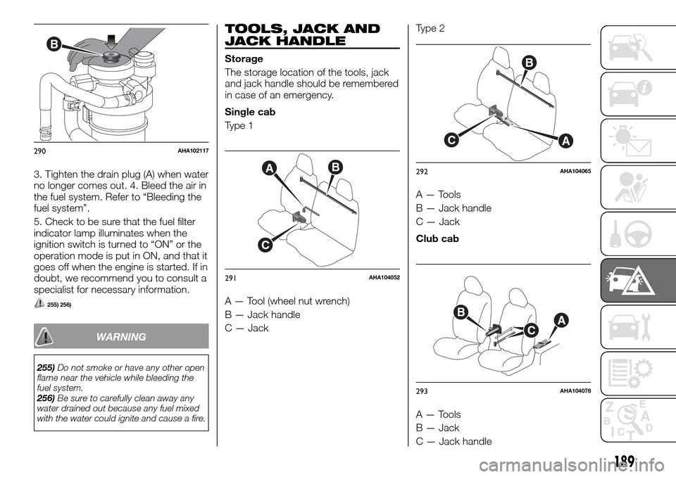
3. Tighten the drain plug (A) when water
no longer comes out. 4. Bleed the air in
the fuel system. Refer to “Bleeding the
fuel system”.
5. Check to be sure that the fuel filter
indicator lamp illuminates when the
ignition switch is turned to “ON” or the
operation mode is put in ON, and that it
goes off when the engine is started. If in
doubt, we recommend you to consult a
specialist for necessary information.
255) 256)
WARNING
255)Do not smoke or have any other open
flame near the vehicle while bleeding the
fuel system.
256)Be sure to carefully clean away any
water drained out because any fuel mixed
with the water could ignite and cause a fire.
TOOLS, JACK AND
JACK HANDLE
Storage
The storage location of the tools, jack
and jack handle should be remembered
in case of an emergency.
Single cab
Type 1
A — Tool (wheel nut wrench)
B — Jack handle
C — JackType 2
A — Tools
B — Jack handle
C — Jack
Club cab
A — Tools
B — Jack
C — Jack handle
B
290AHA102117
AB
C
291AHA104052
B
CA
292AHA104065
BAC
293AHA104078
189
Page 192 of 312
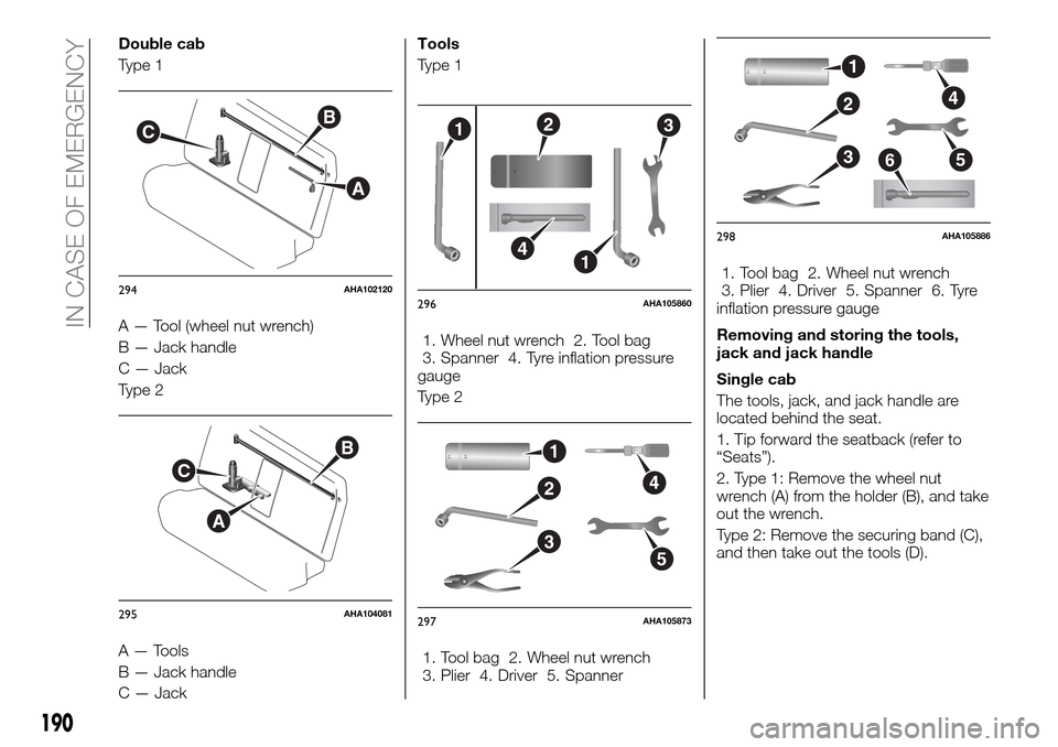
Double cab
Type 1
A — Tool (wheel nut wrench)
B — Jack handle
C — Jack
Type 2
A — Tools
B — Jack handle
C — JackTools
Type 1
1. Wheel nut wrench 2. Tool bag
3. Spanner 4. Tyre inflation pressure
gauge
Type 2
1. Tool bag 2. Wheel nut wrench
3. Plier 4. Driver 5. Spanner1. Tool bag 2. Wheel nut wrench
3. Plier 4. Driver 5. Spanner 6. Tyre
inflation pressure gauge
Removing and storing the tools,
jack and jack handle
Single cab
The tools, jack, and jack handle are
located behind the seat.
1. Tip forward the seatback (refer to
“Seats”).
2. Type 1: Remove the wheel nut
wrench (A) from the holder (B), and take
out the wrench.
Type 2: Remove the securing band (C),
and then take out the tools (D).
B
A
C
294AHA102120
A
C
B
295AHA104081
123
41
296AHA105860
1
4
5
2
3
297AHA105873
1
4
5
2
36
298AHA105886
190
IN CASE OF EMERGENCY
Page 193 of 312
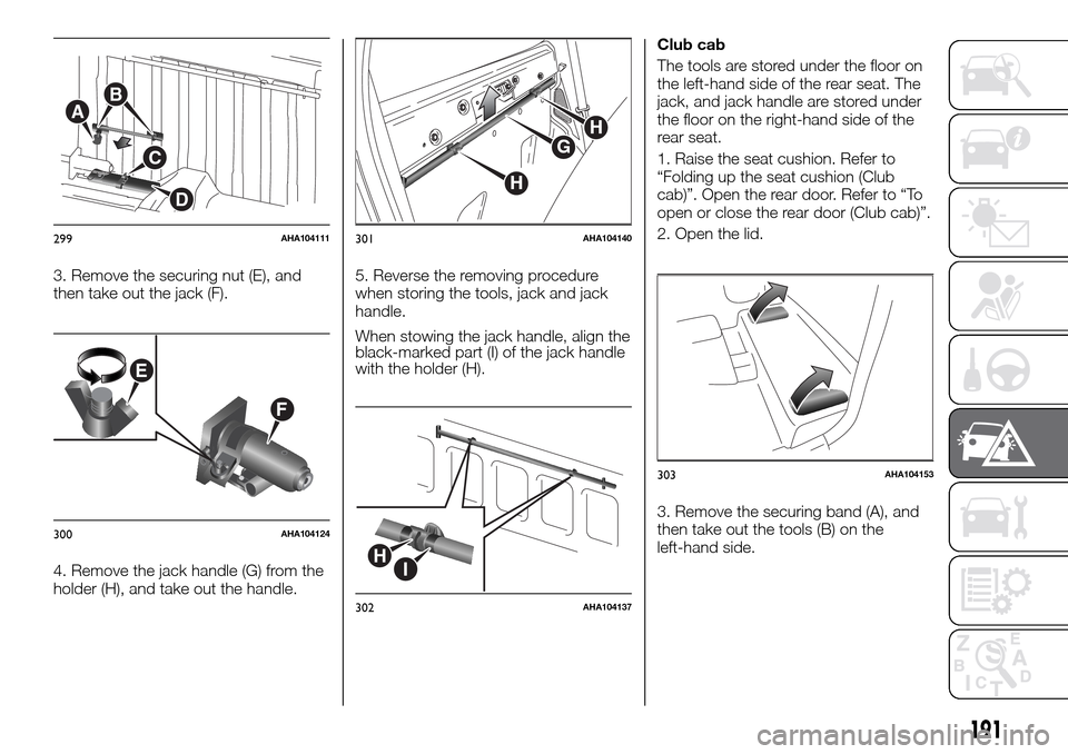
3. Remove the securing nut (E), and
then take out the jack (F).
4. Remove the jack handle (G) from the
holder (H), and take out the handle.5. Reverse the removing procedure
when storing the tools, jack and jack
handle.
When stowing the jack handle, align the
black-marked part (I) of the jack handle
with the holder (H).Club cab
The tools are stored under the floor on
the left-hand side of the rear seat. The
jack, and jack handle are stored under
the floor on the right-hand side of the
rear seat.
1. Raise the seat cushion. Refer to
“Folding up the seat cushion (Club
cab)”. Open the rear door. Refer to “To
open or close the rear door (Club cab)”.
2. Open the lid.
3. Remove the securing band (A), and
then take out the tools (B) on the
left-hand side.
A
C
D
B
299AHA104111
E
F
300AHA104124
H
H
G
301AHA104140
HI
302AHA104137
303AHA104153
191
Page 194 of 312
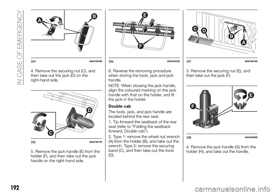
4. Remove the securing nut (C), and
then take out the jack (D) on the
right-hand side.
5. Remove the jack handle (E) from the
holder (F), and then take out the jack
handle on the right-hand side.6. Reverse the removing procedure
when storing the tools, jack and jack
handle.
NOTE When stowing the jack handle,
align the coloured marking on the jack
handle with that on the holder, and fit
the jack in the holder.
Double cab
The tools, jack, and jack handle are
located behind the rear seat.
1. Tip forward the seatback of the rear
seat (refer to “Folding the seatback
forward, Double cab”).
2. Type 1: remove the wheel nut wrench
(A) from the holder (B), and take out the
wrench. Type 2: remove the securing
band (C), and then take out the tools
(D).3. Remove the securing nut (E), and
then take out the jack (F).
4. Remove the jack handle (G) from the
holder (H), and take out the handle.
AB
304AHA104166
C
D
305AHA104179
F
E
306AHA104182
B
A
CD
307AHA104195
E
F
308AHA104209
192
IN CASE OF EMERGENCY
Page 195 of 312
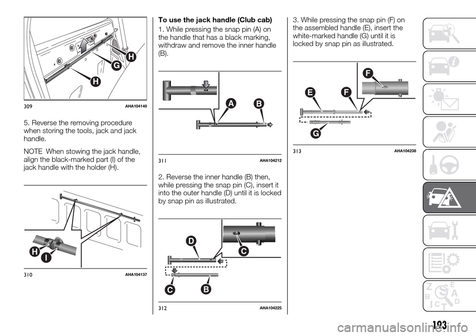
5. Reverse the removing procedure
when storing the tools, jack and jack
handle.
NOTE When stowing the jack handle,
align the black-marked part (I) of the
jack handle with the holder (H).To use the jack handle (Club cab)
1. While pressing the snap pin (A) on
the handle that has a black marking,
withdraw and remove the inner handle
(B).
2. Reverse the inner handle (B) then,
while pressing the snap pin (C), insert it
into the outer handle (D) until it is locked
by snap pin as illustrated.3. While pressing the snap pin (F) on
the assembled handle (E), insert the
white-marked handle (G) until it is
locked by snap pin as illustrated.
H
H
G
309AHA104140
HI
310AHA104137
AB
311AHA104212
D
C
CB
312AHA104225
E
G
F
F
313AHA104238
193
Page 196 of 312
HOW TO CHANGE A
TYRE
132) 133)
Before changing a tyre, first stop your
vehicle in a safe, flat location.
1. Park the vehicle on level and stable
ground, free of loose pebbles, etc.
2. Set the parking brake firmly.
3. On vehicles with manual
transmission, turn the ignition switch to
the “LOCK” position or put the
operation mode in OFF, and move the
gearshift lever to the “R” (Reverse)
position. On vehicles with automatic
transmission, move the selector lever to
the “P” (PARK) position, and turn the
ignition switch to the “LOCK” position
or put the operation mode in OFF.
4. Turn on the hazard flashers and set
up a warning triangle, flashing signal
lamp, etc., at an adequate distance
from the vehicle, and have all your
passengers leave the vehicle.
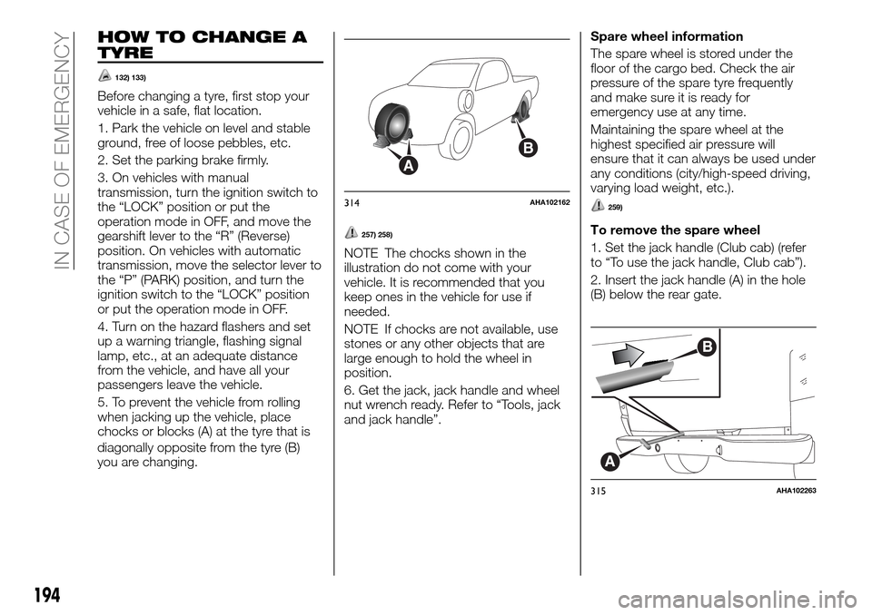
5. To prevent the vehicle from rolling
when jacking up the vehicle, place
chocks or blocks (A) at the tyre that is
diagonally opposite from the tyre (B)
you are changing.
257) 258)
NOTE The chocks shown in the
illustration do not come with your
vehicle. It is recommended that you
keep ones in the vehicle for use if
needed.
NOTE If chocks are not available, use
stones or any other objects that are
large enough to hold the wheel in
position.
6. Get the jack, jack handle and wheel
nut wrench ready. Refer to “Tools, jack
and jack handle”.Spare wheel information
The spare wheel is stored under the
floor of the cargo bed. Check the air
pressure of the spare tyre frequently
and make sure it is ready for
emergency use at any time.
Maintaining the spare wheel at the
highest specified air pressure will
ensure that it can always be used under
any conditions (city/high-speed driving,
varying load weight, etc.).
259)
To remove the spare wheel
1. Set the jack handle (Club cab) (refer
to “To use the jack handle, Club cab”).
2. Insert the jack handle (A) in the hole
(B) below the rear gate.
A
B
314AHA102162
A
B
315AHA102263
194
IN CASE OF EMERGENCY
Page 197 of 312
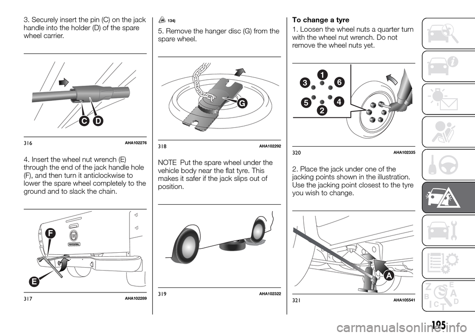
3. Securely insert the pin (C) on the jack
handle into the holder (D) of the spare
wheel carrier.
4. Insert the wheel nut wrench (E)
through the end of the jack handle hole
(F), and then turn it anticlockwise to
lower the spare wheel completely to the
ground and to slack the chain.134)
5. Remove the hanger disc (G) from the
spare wheel.
NOTE Put the spare wheel under the
vehicle body near the flat tyre. This
makes it safer if the jack slips out of
position.To change a tyre
1. Loosen the wheel nuts a quarter turn
with the wheel nut wrench. Do not
remove the wheel nuts yet.
2. Place the jack under one of the
jacking points shown in the illustration.
Use the jacking point closest to the tyre
you wish to change.
CD
316AHA102276
F
E
317AHA102289
G
318AHA102292
319AHA102322
1
2
3
45
6
320AHA102335
A
321AHA105541
195
Page 198 of 312
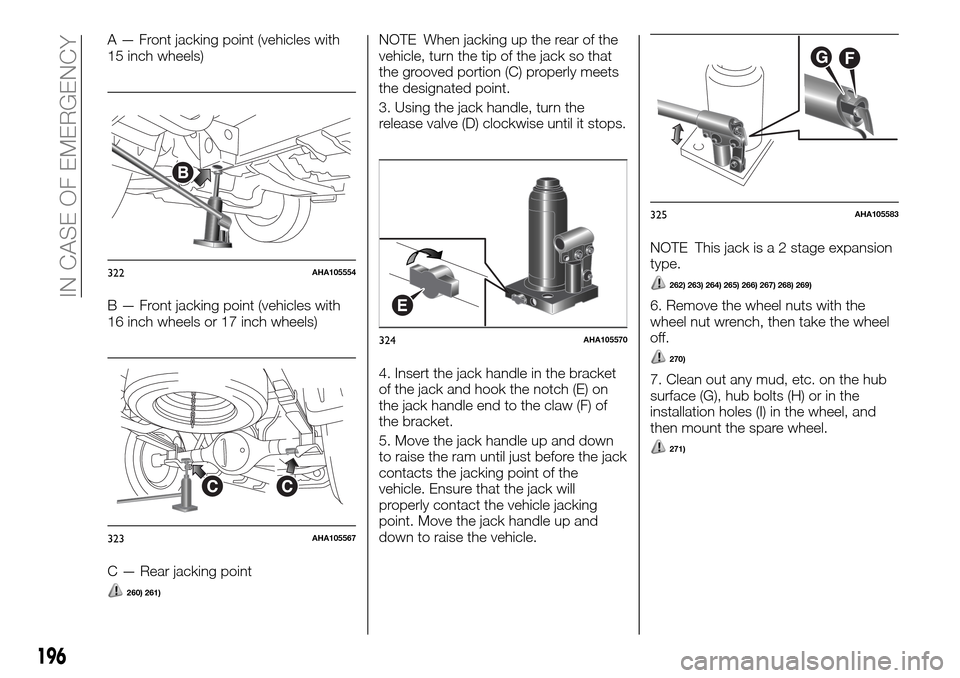
A — Front jacking point (vehicles with
15 inch wheels)
B — Front jacking point (vehicles with
16 inch wheels or 17 inch wheels)
C — Rear jacking point
260) 261)
NOTE When jacking up the rear of the
vehicle, turn the tip of the jack so that
the grooved portion (C) properly meets
the designated point.
3. Using the jack handle, turn the
release valve (D) clockwise until it stops.
4. Insert the jack handle in the bracket
of the jack and hook the notch (E) on
the jack handle end to the claw (F) of
the bracket.
5. Move the jack handle up and down
to raise the ram until just before the jack
contacts the jacking point of the
vehicle. Ensure that the jack will
properly contact the vehicle jacking
point. Move the jack handle up and
down to raise the vehicle.NOTE This jack is a 2 stage expansion
type.
262) 263) 264) 265) 266) 267) 268) 269)
6. Remove the wheel nuts with the
wheel nut wrench, then take the wheel
off.
270)
7. Clean out any mud, etc. on the hub
surface (G), hub bolts (H) or in the
installation holes (I) in the wheel, and
then mount the spare wheel.
271)
B
322AHA105554
CC
323AHA105567
E
324AHA105570
GF
325AHA105583
196
IN CASE OF EMERGENCY
Page 199 of 312
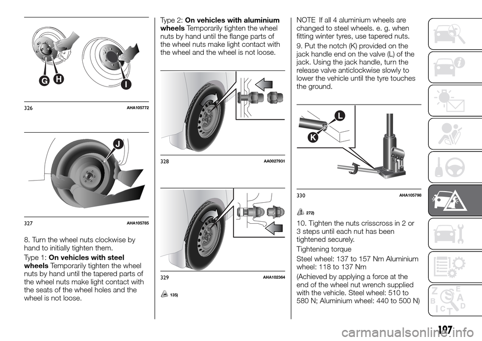
8. Turn the wheel nuts clockwise by
hand to initially tighten them.
Type 1:On vehicles with steel
wheelsTemporarily tighten the wheel
nuts by hand until the tapered parts of
the wheel nuts make light contact with
the seats of the wheel holes and the
wheel is not loose.Type 2:On vehicles with aluminium
wheelsTemporarily tighten the wheel
nuts by hand until the flange parts of
the wheel nuts make light contact with
the wheel and the wheel is not loose.
135)
NOTE If all 4 aluminium wheels are
changed to steel wheels. e. g. when
fitting winter tyres, use tapered nuts.
9. Put the notch (K) provided on the
jack handle end on the valve (L) of the
jack. Using the jack handle, turn the
release valve anticlockwise slowly to
lower the vehicle until the tyre touches
the ground.
272)
10. Tighten the nuts crisscross in 2 or
3 steps until each nut has been
tightened securely.
Tightening torque
Steel wheel: 137 to 157 Nm Aluminium
wheel: 118 to 137 Nm
(Achieved by applying a force at the
end of the wheel nut wrench supplied
with the vehicle. Steel wheel: 510 to
580 N; Aluminium wheel: 440 to 500 N)
GHI
326AHA105772
J
327AHA105785
328AA0027931
329AHA102364
L
K
330AHA105798
197
Page 200 of 312
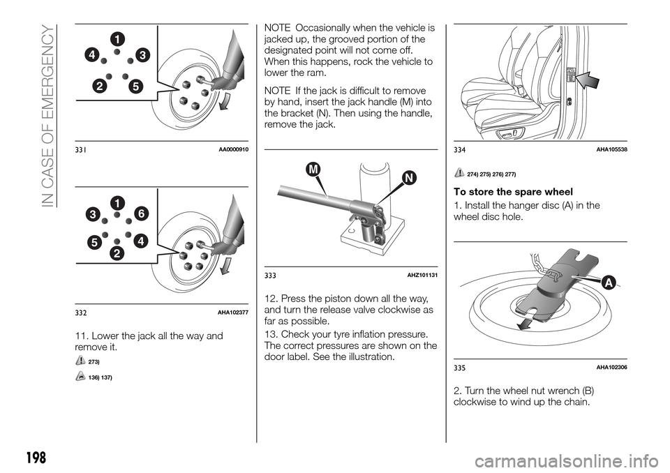
11. Lower the jack all the way and
remove it.
273)
136) 137)
NOTE Occasionally when the vehicle is
jacked up, the grooved portion of the
designated point will not come off.
When this happens, rock the vehicle to
lower the ram.
NOTE If the jack is difficult to remove
by hand, insert the jack handle (M) into
the bracket (N). Then using the handle,
remove the jack.
12. Press the piston down all the way,
and turn the release valve clockwise as
far as possible.
13. Check your tyre inflation pressure.
The correct pressures are shown on the
door label. See the illustration.
274) 275) 276) 277)
To store the spare wheel
1. Install the hanger disc (A) in the
wheel disc hole.
2. Turn the wheel nut wrench (B)
clockwise to wind up the chain.
1
2
34
5
331AA0000910
1
2
3
45
6
332AHA102377
MN
333AHZ101131
334AHA105538
A
335AHA102306
198
IN CASE OF EMERGENCY