low FIAT FULLBACK 2018 Owner handbook (in English)
[x] Cancel search | Manufacturer: FIAT, Model Year: 2018, Model line: FULLBACK, Model: FIAT FULLBACK 2018Pages: 316, PDF Size: 10.52 MB
Page 194 of 316
SPEED LIMITER
The Speed Limiter is a driver assist
function to prevent from exceeding the
speed set by driver while engine power
control.
156)
NOTE If depressing the clutch pedal
(M/T), the Speed Limiter does not
activate.
If the vehicle speed exceeds the set
speed, control state “LIMIT” and the
Speed Limiter’s symbol will blink in the
combination meter.
If the vehicle speed exceeds the set
speed after indicated, control state
“LIMIT” and the beep alert will sound a
certain period of time.
While running without blinked control
state “LIMIT” and the Speed Limiter’s
symbol, if you decrease the set speed
and vehicle speed is more than set
speed, control state “LIMIT” and the
Speed Limiter’s symbol blinking starts
but beep alert is delayed.
In this case, when vehicle speed keeps
exceeding set speed for about
30 seconds after control state “LIMIT”
and the Speed Limiter’s symbol are
blinked, beep alert will sound a certain
period of time.
If the vehicle speeds decreases less
than set speeds, control state “LIMIT”
and the Speed Limiter’s symbol stop
blinking. When beep alert is sounding,
the beep alert also goes off.NOTE However, this gives priority to
audio and visual signal of safety
reasons or driver’s demand. If the set
speed is too lower based on current
shift position, the Speed Limiter may
not limit the vehicle speed to prevent
engine stall.
Speed Limiter control switches
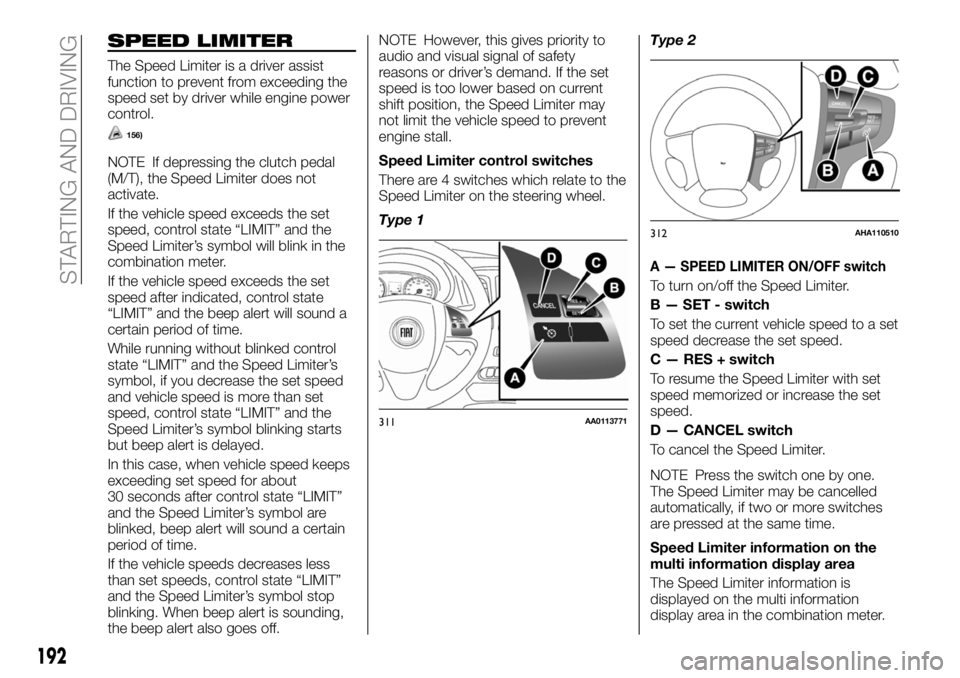
There are 4 switches which relate to the
Speed Limiter on the steering wheel.
Type 1Type 2
A — SPEED LIMITER ON/OFF switch
To turn on/off the Speed Limiter.
B — SET - switch
To set the current vehicle speed to a set
speed decrease the set speed.
C — RES + switch
To resume the Speed Limiter with set
speed memorized or increase the set
speed.
D — CANCEL switch
To cancel the Speed Limiter.
NOTE Press the switch one by one.
The Speed Limiter may be cancelled
automatically, if two or more switches
are pressed at the same time.
Speed Limiter information on the
multi information display area
The Speed Limiter information is
displayed on the multi information
display area in the combination meter.
311AA0113771
312AHA110510
192
STARTING AND DRIVING
Page 195 of 316
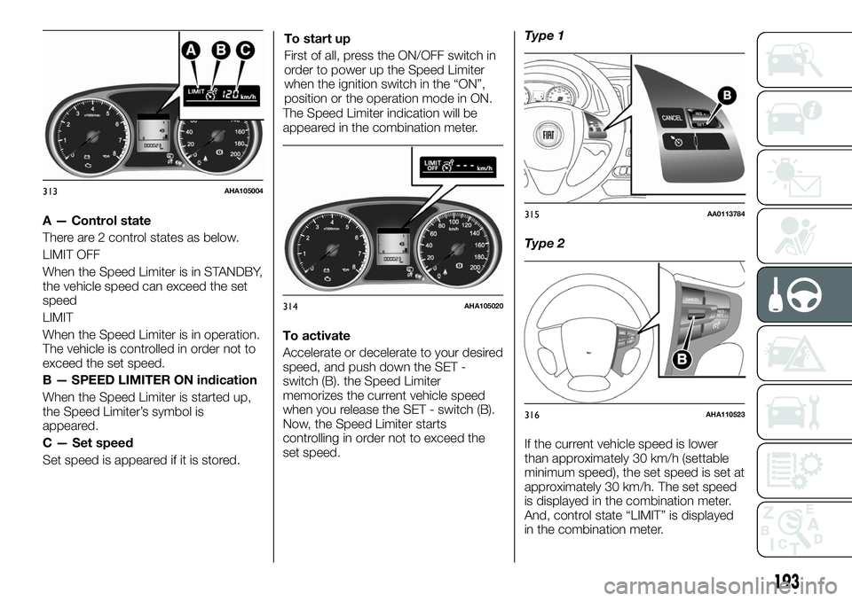
A — Control state
There are 2 control states as below.
LIMIT OFF
When the Speed Limiter is in STANDBY,
the vehicle speed can exceed the set
speed
LIMIT
When the Speed Limiter is in operation.
The vehicle is controlled in order not to
exceed the set speed.
B — SPEED LIMITER ON indication
When the Speed Limiter is started up,
the Speed Limiter’s symbol is
appeared.
C — Set speed
Set speed is appeared if it is stored.To start up
First of all, press the ON/OFF switch in
order to power up the Speed Limiter
when the ignition switch in the “ON”,
position or the operation mode in ON.
The Speed Limiter indication will be
appeared in the combination meter.
To activate
Accelerate or decelerate to your desired
speed, and push down the SET -
switch (B). the Speed Limiter
memorizes the current vehicle speed
when you release the SET - switch (B).
Now, the Speed Limiter starts
controlling in order not to exceed the
set speed.Type 1
Type 2
If the current vehicle speed is lower
than approximately 30 km/h (settable
minimum speed), the set speed is set at
approximately 30 km/h. The set speed
is displayed in the combination meter.
And, control state “LIMIT” is displayed
in the combination meter.
313AHA105004
314AHA105020
315AA0113784
316AHA110523
193
Page 199 of 316
254)
A driver can change the set speed
during this emergency use.
To deactivate
Use whichever following ways to
deactivate.
Press CANCEL switch
Press the Speed Limiter ON/OFF
switch
NOTE If the Speed Limiter is cancelled
by other states, it may be a system
malfunction. Stop using the Speed
Limiter and turn off the Speed Limiter.
Have your vehicle inspected by a Fiat
Dealership.
255)
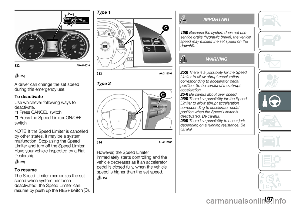
To resume
The Speed Limiter memorizes the set
speed when system has been
deactivated, the Speed Limiter can
resume by push up the RES(C).Type 1
Type 2
However, the Speed Limiter
immediately starts controlling and the
vehicle decreases as if an accelerator
pedal is closed fully, when the vehicle
speed is higher than the set speed.
256)
IMPORTANT
156)Because the system does not use
service brake (hydraulic brake), the vehicle
speed may exceed the set speed on the
downhill.
WARNING
253)There is a possibility for the Speed
Limiter to allow abrupt acceleration
corresponding to accelerator pedal
position. So be careful of the abrupt
acceleration.
254)Be careful about over speed.
255)There is a possibility for the Speed
Limiter to allow abrupt acceleration
corresponding to accelerator pedal
position when the Speed Limiter is
deactivated. Be careful.
256)There is a possibility to occur jerk,
depending on a running resistance. Be
careful.
332AHA105033
333AA0113797
334AHA110536
197
+ switch
Page 200 of 316
LANE DEPARTURE
WARNING
(where provided)
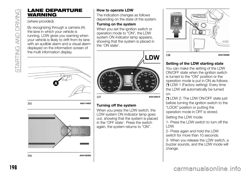
By recognizing through a camera (A)
the lane in which your vehicle is
running, LDW gives you warning when
your vehicle is likely to drift from its lane
with an audible alarm and a visual alarm
displayed on the information screen of
the multi information display.How to operate LDW
The indication changes as follows
depending on the state of the system.
Turning on the system
When you set the ignition switch or
operation mode to “ON”, the LDW
system ON indicator lamp appears,
showing that the system is placed in
the ‘ON state’.
Turning off the system
When you press the LDW switch, the
LDW system ON indicator lamp goes
out, showing that the system is placed
in the ‘OFF state’. Press the switch
again, the system returns to “ON”.Setting of the LDW starting state
You can make the setting of the LDW
ON/OFF state when the ignition switch
is turned to the “ON” position or the
operation mode is put in ON as follows.
LDW 1 (Factory setting): Every time
the LDW will automatically be turned
on.
LDW 2: The LDW ON/OFF state just
before turning the ignition switch to the
“LOCK” position or putting the
operation mode in OFF is stored.
Setting the LDW mode:
1- Press the LDW switch to turn off the
LDW.
2- Press again and hold the LDW
switch for more than 10 seconds.
3- When you release the LDW switch, a
buzzer sounds, and the LDW mode will
change.
335AA0114055
336AHA106359
337AHA106375
338AHA106388
198
STARTING AND DRIVING
Page 201 of 316
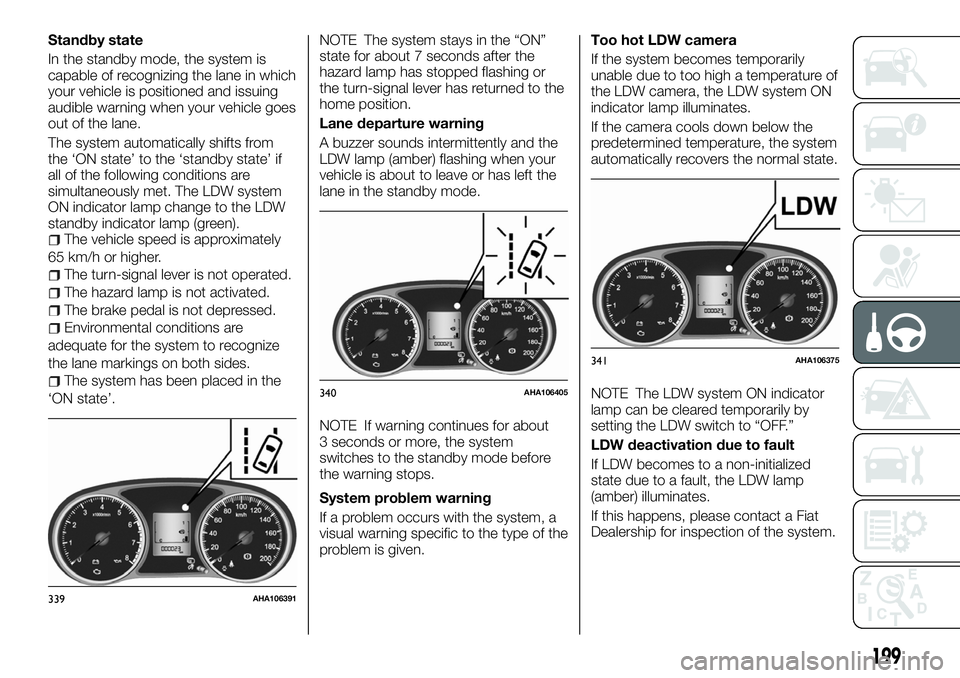
Standby state
In the standby mode, the system is
capable of recognizing the lane in which
your vehicle is positioned and issuing
audible warning when your vehicle goes
out of the lane.
The system automatically shifts from
the ‘ON state’ to the ‘standby state’ if
all of the following conditions are
simultaneously met. The LDW system
ON indicator lamp change to the LDW
standby indicator lamp (green).
The vehicle speed is approximately
65 km/h or higher.
The turn-signal lever is not operated.
The hazard lamp is not activated.
The brake pedal is not depressed.
Environmental conditions are
adequate for the system to recognize
the lane markings on both sides.
The system has been placed in the
‘ON state’.NOTE The system stays in the “ON”
state for about 7 seconds after the
hazard lamp has stopped flashing or
the turn-signal lever has returned to the
home position.
Lane departure warning
A buzzer sounds intermittently and the
LDW lamp (amber) flashing when your
vehicle is about to leave or has left the
lane in the standby mode.
NOTE If warning continues for about
3 seconds or more, the system
switches to the standby mode before
the warning stops.
System problem warning
If a problem occurs with the system, a
visual warning specific to the type of the
problem is given.Too hot LDW camera
If the system becomes temporarily
unable due to too high a temperature of
the LDW camera, the LDW system ON
indicator lamp illuminates.
If the camera cools down below the
predetermined temperature, the system
automatically recovers the normal state.
NOTE The LDW system ON indicator
lamp can be cleared temporarily by
setting the LDW switch to “OFF.”
LDW deactivation due to fault
If LDW becomes to a non-initialized
state due to a fault, the LDW lamp
(amber) illuminates.
If this happens, please contact a Fiat
Dealership for inspection of the system.
339AHA106391
340AHA106405
341AHA106375
199
Page 202 of 316
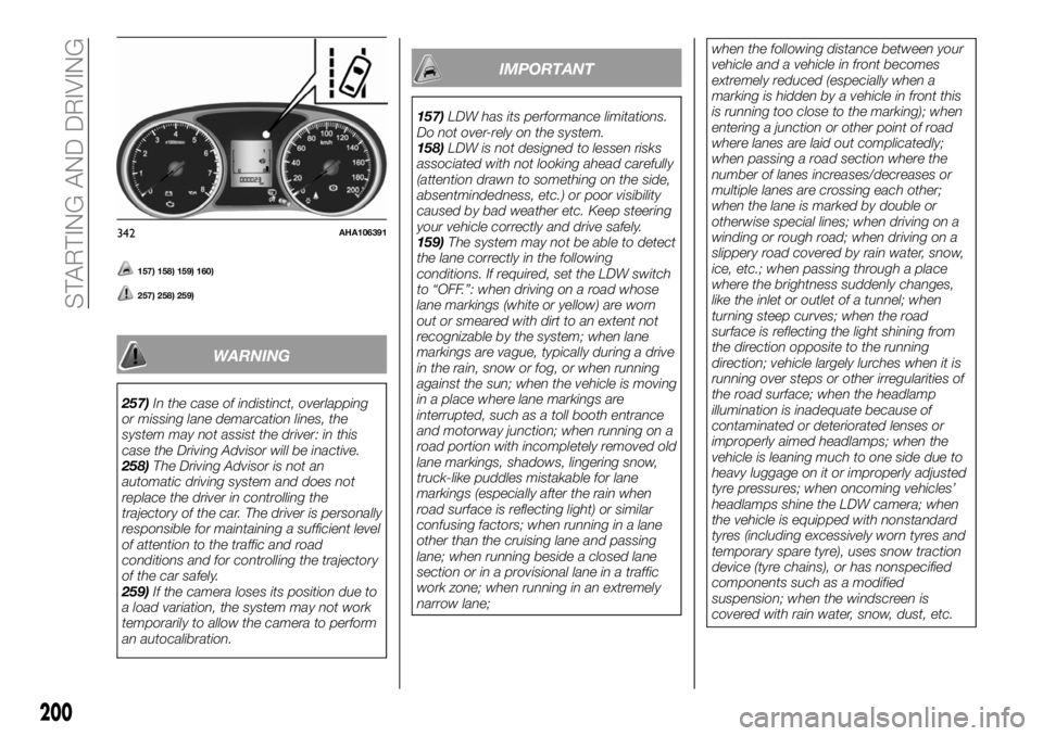
157) 158) 159) 160)
257) 258) 259)
WARNING
257)In the case of indistinct, overlapping
or missing lane demarcation lines, the
system may not assist the driver: in this
case the Driving Advisor will be inactive.
258)The Driving Advisor is not an
automatic driving system and does not
replace the driver in controlling the
trajectory of the car. The driver is personally
responsible for maintaining a sufficient level
of attention to the traffic and road
conditions and for controlling the trajectory
of the car safely.
259)If the camera loses its position due to
a load variation, the system may not work
temporarily to allow the camera to perform
an autocalibration.
IMPORTANT
157)LDW has its performance limitations.
Do not over-rely on the system.
158)LDW is not designed to lessen risks
associated with not looking ahead carefully
(attention drawn to something on the side,
absentmindedness, etc.) or poor visibility
caused by bad weather etc. Keep steering
your vehicle correctly and drive safely.
159)The system may not be able to detect
the lane correctly in the following
conditions. If required, set the LDW switch
to “OFF.”: when driving on a road whose
lane markings (white or yellow) are worn
out or smeared with dirt to an extent not
recognizable by the system; when lane
markings are vague, typically during a drive
in the rain, snow or fog, or when running
against the sun; when the vehicle is moving
in a place where lane markings are
interrupted, such as a toll booth entrance
and motorway junction; when running on a
road portion with incompletely removed old
lane markings, shadows, lingering snow,
truck-like puddles mistakable for lane
markings (especially after the rain when
road surface is reflecting light) or similar
confusing factors; when running in a lane
other than the cruising lane and passing
lane; when running beside a closed lane
section or in a provisional lane in a traffic
work zone; when running in an extremely
narrow lane;when the following distance between your
vehicle and a vehicle in front becomes
extremely reduced (especially when a
marking is hidden by a vehicle in front this
is running too close to the marking); when
entering a junction or other point of road
where lanes are laid out complicatedly;
when passing a road section where the
number of lanes increases/decreases or
multiple lanes are crossing each other;
when the lane is marked by double or
otherwise special lines; when driving on a
winding or rough road; when driving on a
slippery road covered by rain water, snow,
ice, etc.; when passing through a place
where the brightness suddenly changes,
like the inlet or outlet of a tunnel; when
turning steep curves; when the road
surface is reflecting the light shining from
the direction opposite to the running
direction; vehicle largely lurches when it is
running over steps or other irregularities of
the road surface; when the headlamp
illumination is inadequate because of
contaminated or deteriorated lenses or
improperly aimed headlamps; when the
vehicle is leaning much to one side due to
heavy luggage on it or improperly adjusted
tyre pressures; when oncoming vehicles’
headlamps shine the LDW camera; when
the vehicle is equipped with nonstandard
tyres (including excessively worn tyres and
temporary spare tyre), uses snow traction
device (tyre chains), or has nonspecified
components such as a modified
suspension; when the windscreen is
covered with rain water, snow, dust, etc.
342AHA106391
200
STARTING AND DRIVING
Page 203 of 316
160)Follow the instructions given below to
keep your LDW in good operating
conditions: always keep the windscreen
clean; avoid applying a strong shock or
pressure to the LDW camera. Do not
attempt to disassemble it; disturbing the
installation of the LDW camera or its
removal is under no circumstances
permitted. The camera has been precisely
oriented at the factory; do not put anything
like a sticker on the area in front of the LDW
camera lens of the windscreen; use only
GENUINE Parts when replacing the
windscreen wipers.REAR VIEW CAMERA
(where provided)
The rear view camera is a system that
shows the view behind the vehicle on a
screen of the Multi Communication
System (MCS), the Smartphone Link
Display Audio or the DISPLAY AUDIO.
260) 261) 262)
161)
Range of view of rear view camera
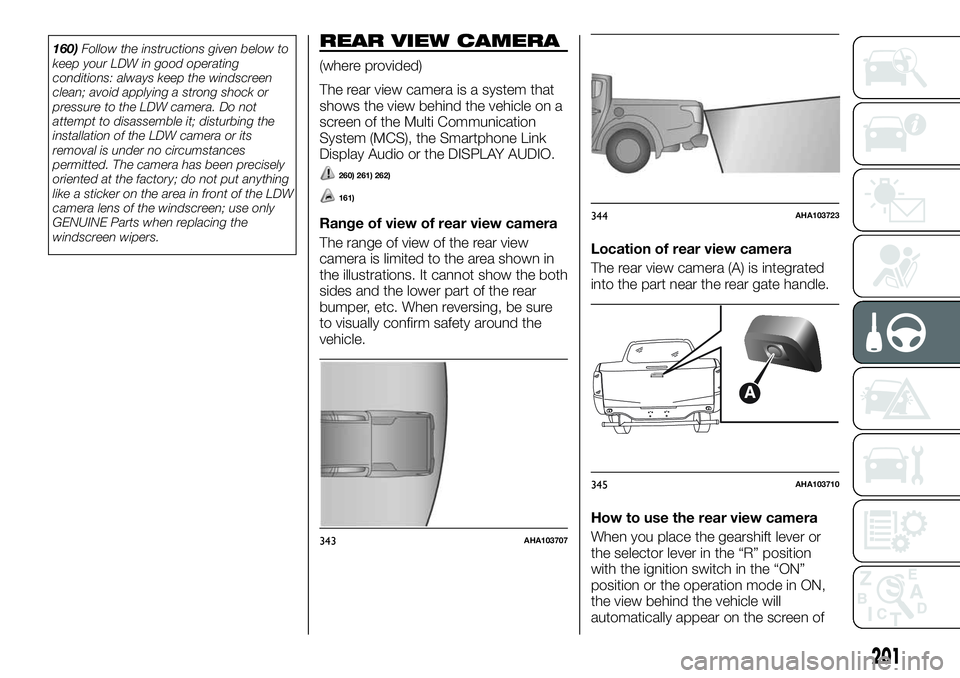
The range of view of the rear view
camera is limited to the area shown in
the illustrations. It cannot show the both
sides and the lower part of the rear
bumper, etc. When reversing, be sure
to visually confirm safety around the
vehicle.Location of rear view camera
The rear view camera (A) is integrated
into the part near the rear gate handle.
How to use the rear view camera
When you place the gearshift lever or
the selector lever in the “R” position
with the ignition switch in the “ON”
position or the operation mode in ON,
the view behind the vehicle will
automatically appear on the screen of
343AHA103707
344AHA103723
345AHA103710
201
Page 204 of 316
the Multi Communication System
(MCS), the Smartphone Link Display
Audio or the DISPLAY AUDIO. When
you move the gearshift lever or the
selector lever to any other position, the
screen will return to its original
indication.
162)
NOTE Because the rear view camera
has a special lens, the lines on the
ground between parking spaces may
not look parallel on the screen.
NOTE In the following situations, the
screen indication may be difficult to see.
There is no abnormality.
Low light (night time)
When the light of the sun or the light
from a vehicle’s headlamps shines
directly into the lens
If a fluorescent light shines directly
into the lens, the screen indication may
be flicker. There is no abnormality.
NOTE If the camera is hot and is then
cooled by rain or a car wash, the lens
can mist up. This phenomenon does
not indicate a malfunction.
NOTE If the atmospheric temperature
is extremely hot or extremely cold, the
rear view camera images may not be
clear. There is no abnormality.NOTE If a radio set is installed near the
camera, the rear view camera images
may cause electrical system
interference and the system may stop
functioning properly.
NOTE It is not possible to fully see
obstacles when the lens is dirty. If the
lens becomes contaminated by water
droplets, snow, mud, or oil, wipe off the
contamination, taking care not to
scratch the lens.
NOTE Please observe the following
cautions. Ignoring them could lead to a
camera malfunction.
Do not subject the camera to
physical shock such as striking it
strongly or throwing a thing.
Do not adhere organic substances,
waxes, oil remover, and glass cleaner to
the camera. If adhered to them,
immediately wipe off.
Do not splash the camera with
boiling water.
Never spray or splash water on the
camera or around it.
Do not disconnect, disassemble or
modify the camera.
Do not scratch the camera, as this
may cause damage to the rear view
camera images.
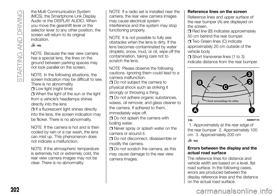
Reference lines on the screen
Reference lines and upper surface of
the rear bumper (A) are displayed on
the screen.
Red line (B) indicates approximately
50 cm behind the rear bumper.
Two Green lines (C) indicate
approximately 20 cm outside of the
vehicle body
Short transverse lines (1 to 3)
indicate distance from the rear bumper.
1. Approximately at the rear edge of
the rear bumper 2. Approximately 100
cm 3. Approximately 200 cm
163)
Errors between the display and the
actual road surface
The reference lines for distance and
vehicle width are based on a level, flat
road surface. In the following cases,
errors are produced between the
display reference lines and the distance
on the actual road surface.
346AG0027115
202
STARTING AND DRIVING
Page 205 of 316
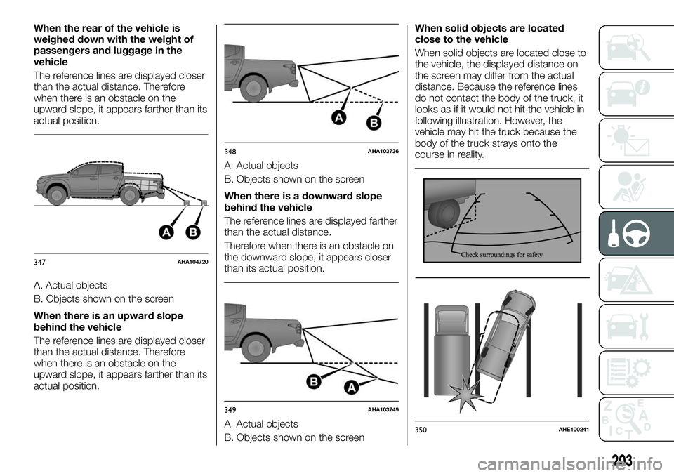
When the rear of the vehicle is
weighed down with the weight of
passengers and luggage in the
vehicle
The reference lines are displayed closer
than the actual distance. Therefore
when there is an obstacle on the
upward slope, it appears farther than its
actual position.
A. Actual objects
B. Objects shown on the screen
When there is an upward slope
behind the vehicle
The reference lines are displayed closer
than the actual distance. Therefore
when there is an obstacle on the
upward slope, it appears farther than its
actual position.A. Actual objects
B. Objects shown on the screen
When there is a downward slope
behind the vehicle
The reference lines are displayed farther
than the actual distance.
Therefore when there is an obstacle on
the downward slope, it appears closer
than its actual position.
A. Actual objects
B. Objects shown on the screenWhen solid objects are located
close to the vehicle
When solid objects are located close to
the vehicle, the displayed distance on
the screen may differ from the actual
distance. Because the reference lines
do not contact the body of the truck, it
looks as if it would not hit the vehicle in
following illustration. However, the
vehicle may hit the truck because the
body of the truck strays onto the
course in reality.
347AHA104720
348AHA103736
349AHA103749
350AHE100241
203
Page 206 of 316
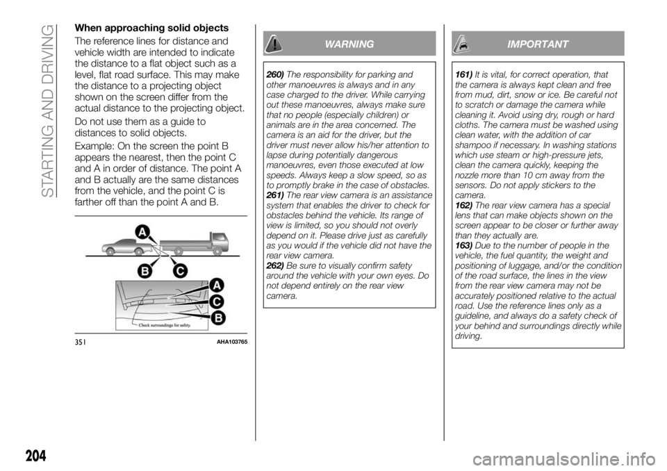
When approaching solid objects
The reference lines for distance and
vehicle width are intended to indicate
the distance to a flat object such as a
level, flat road surface. This may make
the distance to a projecting object
shown on the screen differ from the
actual distance to the projecting object.
Do not use them as a guide to
distances to solid objects.
Example: On the screen the point B
appears the nearest, then the point C
and A in order of distance. The point A
and B actually are the same distances
from the vehicle, and the point C is
farther off than the point A and B.
WARNING
260)The responsibility for parking and
other manoeuvres is always and in any
case charged to the driver. While carrying
out these manoeuvres, always make sure
that no people (especially children) or
animals are in the area concerned. The
camera is an aid for the driver, but the
driver must never allow his/her attention to
lapse during potentially dangerous
manoeuvres, even those executed at low
speeds. Always keep a slow speed, so as
to promptly brake in the case of obstacles.
261)The rear view camera is an assistance
system that enables the driver to check for
obstacles behind the vehicle. Its range of
view is limited, so you should not overly
depend on it. Please drive just as carefully
as you would if the vehicle did not have the
rear view camera.
262)Be sure to visually confirm safety
around the vehicle with your own eyes. Do
not depend entirely on the rear view
camera.
IMPORTANT
161)It is vital, for correct operation, that
the camera is always kept clean and free
from mud, dirt, snow or ice. Be careful not
to scratch or damage the camera while
cleaning it. Avoid using dry, rough or hard
cloths. The camera must be washed using
clean water, with the addition of car
shampoo if necessary. In washing stations
which use steam or high-pressure jets,
clean the camera quickly, keeping the
nozzle more than 10 cm away from the
sensors. Do not apply stickers to the
camera.
162)The rear view camera has a special
lens that can make objects shown on the
screen appear to be closer or further away
than they actually are.
163)Due to the number of people in the
vehicle, the fuel quantity, the weight and
positioning of luggage, and/or the condition
of the road surface, the lines in the view
from the rear view camera may not be
accurately positioned relative to the actual
road. Use the reference lines only as a
guideline, and always do a safety check of
your behind and surroundings directly while
driving.
351AHA103765
204
STARTING AND DRIVING