ECU FIAT GRANDE PUNTO 2008 199 / 1.G Owners Manual
[x] Cancel search | Manufacturer: FIAT, Model Year: 2008, Model line: GRANDE PUNTO, Model: FIAT GRANDE PUNTO 2008 199 / 1.GPages: 242, PDF Size: 4.06 MB
Page 86 of 242
85
SAFETY
DEVICES
CORRECT USE
OF THE CAR
WARNING
LIGHTS AND
MESSAGES
IIN AN
EMERGENCY
CAR
MAINTENANCE
TECHNICAL
SPECIFICATIONS
INDEX
DASHBOARD
AND CONTROLS
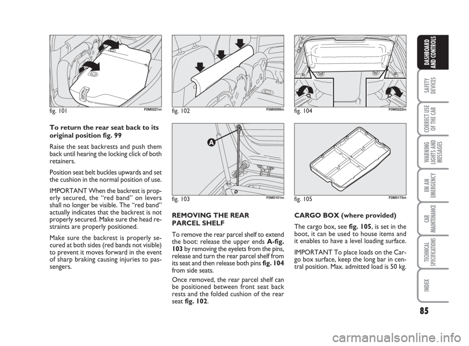
fig. 103F0M0101m
fig. 102F0M0099mfig. 101F0M0221mfig. 104F0M0222m
REMOVING THE REAR
PARCEL SHELF
To remove the rear parcel shelf to extend
the boot: release the upper ends A-fig.
103by removing the eyelets from the pins,
release and turn the rear parcel shelf from
its seat and then release both pins fig. 104
from side seats.
Once removed, the rear parcel shelf can
be positioned between front seat back
rests and the folded cushion of the rear
seat fig. 102.CARGO BOX (where provided)
The cargo box, see fig. 105, is set in the
boot, it can be used to house items and
it enables to have a level loading surface.
IMPORTANT To place loads on the Car-
go box surface, keep the long bar in cen-
tral position. Max. admitted load is 50 kg. To return the rear seat back to its
original position fig. 99
Raise the seat backrests and push them
back until hearing the locking click of both
retainers.
Position seat belt buckles upwards and set
the cushion in the normal position of use.
IMPORTANT When the backrest is prop-
erly secured, the “red band” on levers
shall no longer be visible. The “red band”
actually indicates that the backrest is not
properly secured. Make sure the head re-
straints are properly positioned.
Make sure the backrest is properly se-
cured at both sides (red bands not visible)
to prevent it moves forward in the event
of sharp braking causing injuries to pas-
sengers.
fig. 105F0M0175m
037-087 Punto GDX GB 31-07-2008 17:25 Pagina 85
Page 112 of 242
111
CORRECT USE
OF THE CAR
WARNING
LIGHTS AND
MESSAGES
IN AN
EMERGENCY
CAR
MAINTENANCE
TECHNICAL
SPECIFICATIONS
INDEX
DASHBOARD
AND CONTROLS
SAFETY
DEVICES
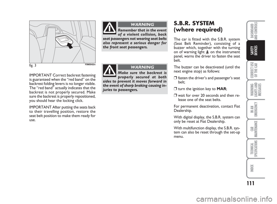
IMPORTANT Correct backrest fastening
is guaranteed when the “red band” on the
backrest folding levers is no longer visible.
The “red band” actually indicates that the
backrest is not properly secured. Make
sure the backrest is properly repositioned,
you should hear the locking click.
IMPORTANT After putting the seats back
to their travelling position, restore the
seat belt position to make them ready for
use.
S.B.R. SYSTEM
(where required)
The car is fitted with the S.B.R. system
(Seat Belt Reminder), consisting of a
buzzer which, together with the turning
on of warning light
belt.
The buzzer can be deactivated (until the
next engine stop) as follows:
❒ fasten the driver’s and passenger’s seat
belt;
❒turn the ignition key to MAR;
❒wait for over 20 seconds and then re-
lease one of the seat belts.
For permanent deactivation, contact Fiat
Dealership.
With digital display, the S.B.R. system can
only be reset at Fiat Dealership.
With multifunction display, the S.B.R. sys-
tem can also be reset through the set-up
menu.
fig. 3F0M0042m
Remember that in the event
of a violent collision, back
seat passengers not wearing seat belts
also represent a serious danger for
the front seat passengers.
WARNING
Make sure the backrest is
properly secured at both
sides to prevent it moves forward in
the event of sharp braking causing in-
juries to passengers.
WARNING
109-126 Punto GDX GB 31-07-2008 17:26 Pagina 111
Page 121 of 242
120
CORRECT USE
OF THE CAR
WARNING
LIGHTS AND
MESSAGES
IN AN
EMERGENCY
CAR
MAINTENANCE
TECHNICAL
SPECIFICATIONS
IINDEX
DASHBOARD
AND CONTROLS
SAFETY
DEVICES
PRESETTING FOR
MOUNTING THE
“UNIVERSAL ISOFIX”
CHILD RESTRAINT
SYSTEM
This car is preset for mounting the Uni-
versal Isofix child restraint system, a new
European standardised system for carry-
ing children safely.
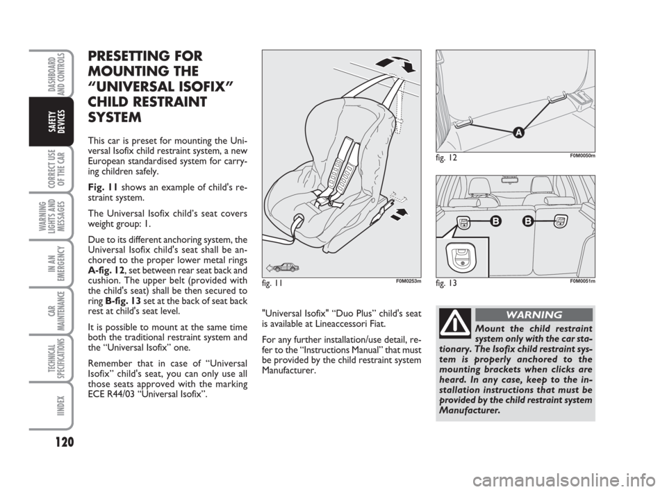
Fig. 11shows an example of child's re-
straint system.
The Universal Isofix child’s seat covers
weight group: 1.
Due to its different anchoring system, the
Universal Isofix child's seat shall be an-
chored to the proper lower metal rings
A-fig. 12, set between rear seat back and
cushion. The upper belt (provided with
the child's seat) shall be then secured to
ring B-fig. 13set at the back of seat back
rest at child's seat level.
It is possible to mount at the same time
both the traditional restraint system and
the “Universal Isofix” one.
Remember that in case of “Universal
Isofix” child's seat, you can only use all
those seats approved with the marking
ECE R44/03 “Universal Isofix”.
fig. 12F0M0050m
fig. 11F0M0253mfig. 13F0M0051m
Mount the child restraint
system only with the car sta-
tionary. The Isofix child restraint sys-
tem is properly anchored to the
mounting brackets when clicks are
heard. In any case, keep to the in-
stallation instructions that must be
provided by the child restraint system
Manufacturer.
WARNING"Universal Isofix" “Duo Plus” child's seat
is available at Lineaccessori Fiat.
For any further installation/use detail, re-
fer to the “Instructions Manual” that must
be provided by the child restraint system
Manufacturer.
109-126 Punto GDX GB 31-07-2008 17:26 Pagina 120
Page 136 of 242
135
WARNING
LIGHTS AND
MESSAGES
IN AN
EMERGENCY
CAR
MAINTENANCE
TECHNICAL
SPECIFICATIONS
INDEX
DASHBOARD
AND CONTROLS
SAFETY
DEVICES
CORRECT USE
OF THE CAR
INSTALLING THE TOW HOOK
The towing device should be fastened to
the body by specialised personnel accord-
ing to any additional and/or integrative in-
formation supplied by the Manufacturer of
the device.
The towing device must meet current reg-
ulations with reference to 94/20/EC Di-
rective and subsequent amendments.
For any version the towing device used
must match the towable weight of the car
on which it is to be installed.
For the electric connection a unified con-
nector should be used which is generally
placed on a special bracket normally fas-
tened to the towing device, and a special
ECU for external trailer light control shall
be installed on the car.
For the electrical connection, 7 or 13 pin
12VDC connection is to be used (CU-
NA/UNI and ISO/DIN Standards). Follow
the instructions provided by the car man-
ufacturer and/or the tow hitch manufac-
turer.An electric brake should be supplied di-
rectly by the battery through a cable with
a cross section of no less than 2.5 mm
2.
IMPORTANT Electric brake or other de-
vice shall be used with running engine.
In addition to the electrical branches, the
car’s electric system can only be con-
nected to the supply cable for an electric
brake and to the cable for an internal light,
though not above 15W.
For connections use the preset control
unit with battery cable no less than 2.5
mm
2. Do not exceed the speed limits of the
country you are driving in. In any case do
not exceed 100 km/h.
Fit a suitable towing stabilizer to the trail-
er to be towed.
The ABS system with which
the car may be fitted does
not control the trailer braking system.
Therefore be cautious on slippery
roads.
WARNING
Under no circumstances
should the car brake system
be altered to control the trailer brake.
The trailer braking system must be
fully independent of the car’s hy-
draulic system.
WARNING
127-138 Punto GDX GB 31-07-2008 17:27 Pagina 135
Page 174 of 242
173
WARNING
LIGHTS AND
MESSAGES
CAR
MAINTENANCE
TECHNICAL
SPECIFICATIONS
INDEX
DASHBOARD
AND CONTROLS
SAFETY
DEVICES
CORRECT USE
OF THE CAR
IN AN
EMERGENCY
IF AN INTERIOR LIGHT
BURNS OUT
For the type of bulb and power rating, see
“When needing to change a bulb”.
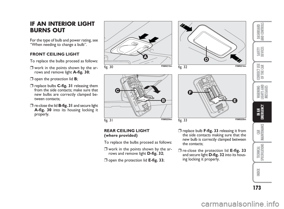
FRONT CEILING LIGHT
To replace the bulbs proceed as follows:
❒work in the points shown by the ar-
rows and remove light A-fig. 30;
❒open the protection lid B;
❒replace bulbs C-fig. 31releasing them
from the side contacts; make sure that
new bulbs are correctly clamped be-
tween contacts;
❒re-close the lid B-fig. 31and secure light
A-fig. 30into its housing locking it
properly.
REAR CEILING LIGHT
(where provided)
To replace the bulbs proceed as follows:
❒work in the points shown by the ar-
rows and remove light D-fig. 32;
❒open the protection lid E-fig. 33;
❒replace bulb F-fig. 33releasing it from
the side contacts making sure that the
new bulb is correctly clamped between
the contacts;
❒re-close the protection lid E-fig. 33
and secure light D-fig. 32into its hous-
ing locking it properly.
fig. 30F0M0213m
fig. 31F0M0234m
fig. 32F0M0214m
fig. 33F0M0235m
153-186 Punto GDX GB 31-07-2008 17:28 Pagina 173