ESP FIAT IDEA 2007 1.G User Guide
[x] Cancel search | Manufacturer: FIAT, Model Year: 2007, Model line: IDEA, Model: FIAT IDEA 2007 1.GPages: 314, PDF Size: 4.78 MB
Page 93 of 314
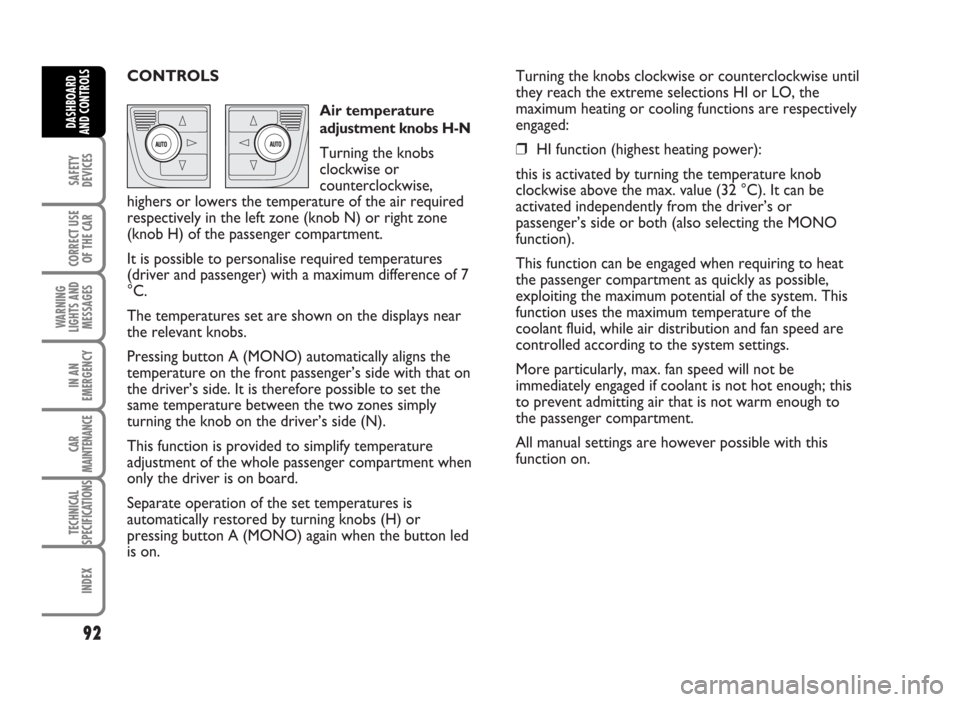
CONTROLS
Air temperature
adjustment knobs H-N
Turning the knobs
clockwise or
counterclockwise,
highers or lowers the temperature of the air required
respectively in the left zone (knob N) or right zone
(knob H) of the passenger compartment.
It is possible to personalise required temperatures
(driver and passenger) with a maximum difference of 7
°C.
The temperatures set are shown on the displays near
the relevant knobs.
Pressing button A (MONO) automatically aligns the
temperature on the front passenger’s side with that on
the driver’s side. It is therefore possible to set the
same temperature between the two zones simply
turning the knob on the driver’s side (N).
This function is provided to simplify temperature
adjustment of the whole passenger compartment when
only the driver is on board.
Separate operation of the set temperatures is
automatically restored by turning knobs (H) or
pressing button A (MONO) again when the button led
is on.Turning the knobs clockwise or counterclockwise until
they reach the extreme selections HI or LO, the
maximum heating or cooling functions are respectively
engaged:
❒HI function (highest heating power):
this is activated by turning the temperature knob
clockwise above the max. value (32 °C). It can be
activated independently from the driver’s or
passenger’s side or both (also selecting the MONO
function).
This function can be engaged when requiring to heat
the passenger compartment as quickly as possible,
exploiting the maximum potential of the system. This
function uses the maximum temperature of the
coolant fluid, while air distribution and fan speed are
controlled according to the system settings.
More particularly, max. fan speed will not be
immediately engaged if coolant is not hot enough; this
to prevent admitting air that is not warm enough to
the passenger compartment.
All manual settings are however possible with this
function on.
92
SAFETY
DEVICES
CORRECT USE
OF THE CAR
WARNING
LIGHTS AND
MESSAGES
IN AN
EMERGENCY
CAR
MAINTENANCE
TECHNICAL
SPECIFICATIONS
INDEX
DASHBOARD
AND CONTROLS
Page 95 of 314
Set air flow distribution is indicated by the
corresponding button led switching on.
With a combined function set, pressing a button will
turn on the main function of the button pressed,
together with the functions set yet. Pressing the
button of the active function will turn the function off
(led off).
To restore automatic air distribution control after a
manual selection, press button AUTO.
When the driver selects air distribution towards the
windscreen, also the air distribution on passenger’s
side will automatically be directed to the windscreen.
The passenger can however select a different air
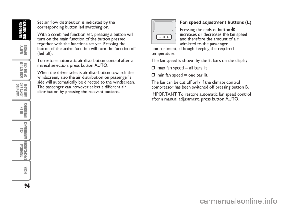
distribution by pressing the relevant buttons.Fan speed adjustment buttons (L)
Pressing the ends of button p
increases or decreases the fan speed
and therefore the amount of air
admitted to the passenger
compartment, although keeping the required
temperature.
The fan speed is shown by the lit bars on the display
❒max fan speed = all bars lit
❒min fan speed = one bar lit.
The fan can be cut off only if the climate control
compressor has been switched off pressing button B.
IMPORTANT To restore automatic fan speed control
after a manual adjustment, press button AUTO.
94
SAFETY
DEVICES
CORRECT USE
OF THE CAR
WARNING
LIGHTS AND
MESSAGES
IN AN
EMERGENCY
CAR
MAINTENANCE
TECHNICAL
SPECIFICATIONS
INDEX
DASHBOARD
AND CONTROLS
Page 97 of 314
These operating conditions are obtained pressing in
sequence the air recirculation button (C).
After a preset time, the climate control system will
turn air recirculation off automatically for safety
reasons, thus enabling outside air inlet.IMPORTANT The air recirculation system
makes it possible to reach the required heating or
cooling conditions faster.
It is however inadvisable to use it on rainy/cold days as
it would considerably increase the possibility of the
windows misting inside, especially if the climate
control system is off.
When the outside temperature is below 5-7°C, air
recirculation is switched off (air is taken from the
outside) to prevent misting.
96
SAFETY
DEVICES
CORRECT USE
OF THE CAR
WARNING
LIGHTS AND
MESSAGES
IN AN
EMERGENCY
CAR
MAINTENANCE
TECHNICAL
SPECIFICATIONS
INDEX
DASHBOARD
AND CONTROLS
WARNINGIt is inadvisable to use the air recirculation feature with low outside temperature
as the windows might mist over quickly.
Page 100 of 314
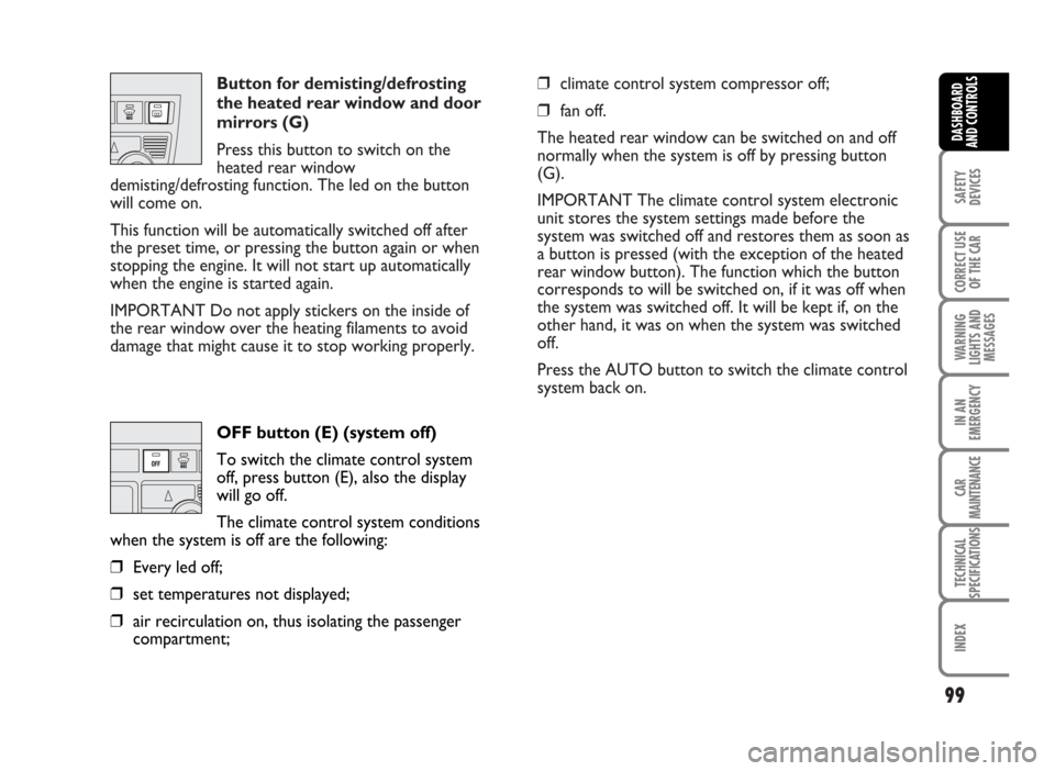
Button for demisting/defrosting
the heated rear window and door
mirrors (G)
Press this button to switch on the
heated rear window
demisting/defrosting function. The led on the button
will come on.
This function will be automatically switched off after
the preset time, or pressing the button again or when
stopping the engine. It will not start up automatically
when the engine is started again.
IMPORTANT Do not apply stickers on the inside of
the rear window over the heating filaments to avoid
damage that might cause it to stop working properly.❒climate control system compressor off;
❒fan off.
The heated rear window can be switched on and off
normally when the system is off by pressing button
(G).
IMPORTANT The climate control system electronic
unit stores the system settings made before the
system was switched off and restores them as soon as
a button is pressed (with the exception of the heated
rear window button). The function which the button
corresponds to will be switched on, if it was off when
the system was switched off. It will be kept if, on the
other hand, it was on when the system was switched
off.
Press the AUTO button to switch the climate control
system back on.
99
SAFETY
DEVICES
CORRECT USE
OF THE CAR
WARNING
LIGHTS AND
MESSAGES
IN AN
EMERGENCY
CAR
MAINTENANCE
TECHNICAL
SPECIFICATIONS
INDEX
DASHBOARD
AND CONTROLS
OFF button (E) (system off)
To switch the climate control system
off, press button (E), also the display
will go off.
The climate control system conditions
when the system is off are the following:
❒Every led off;
❒set temperatures not displayed;
❒air recirculation on, thus isolating the passenger
compartment;
Page 110 of 314
TO INCREASE THE MEMORISED SPEED
The speed memorised can be increased in two ways:
❒pressing the accelerator and then memorising the
new speed reached;
or
❒moving the stalk upwards (+).
Each operation of the stalk will correspond to a slight
increase in speed (about 1 km/h), while keeping the
stalk upwards continuously will correspond to a
continuous speed increase.
109
SAFETY
DEVICES
CORRECT USE
OF THE CAR
WARNING
LIGHTS AND
MESSAGES
IN AN
EMERGENCY
CAR
MAINTENANCE
TECHNICAL
SPECIFICATIONS
INDEX
DASHBOARD
AND CONTROLS
TO MEMORISE SPEED
Proceed as follows:
❒turn the knurled ring (A) to ON and press the
accelerator pedal to the required speed;
❒move the stalk upwards (+) for at least three
seconds, then release it. The car speed is
memorised and it is therefore possible to release
the accelerator pedal.
In the case of need (when overtaking for instance)
acceleration is possible simply pressing the accelerator
pedal: releasing the accelerator pedal, the car will
return to the speed memorised previously.
TO RESET THE MEMORISED SPEED
If the device has been disengaged for example pressing
the brake or clutch pedal, the memorised speed can
be reset as follows:
❒accelerate gradually until reaching a speed
approaching the one memorised;
❒engage the gear selected at the time of speed
memorising (4th or 5th gear);
❒press the RES button (B).
Page 111 of 314
TO REDUCE MEMORISED SPEED
The speed memorised can be increased in two ways:
❒disengaging the device and then memorising the
new speed;
or
❒moving the stalk downwards (–) until reaching the
new speed which will be memorised automatically.
Each operation of the stalk will correspond to a slight
reduction in speed (about 1 km/h), while keeping the
stalk downwards continuously will correspond to a
continuous speed reduction.DEVICE DISENGAGEMENT
Turn the ring (A) to OFF or the ignition key to STOP.
The device is automatically deactivated also in one of
the following cases:
❒pressing the brake or clutch pedal.
110
SAFETY
DEVICES
CORRECT USE
OF THE CAR
WARNING
LIGHTS AND
MESSAGES
IN AN
EMERGENCY
CAR
MAINTENANCE
TECHNICAL
SPECIFICATIONS
INDEX
DASHBOARD
AND CONTROLS
WARNING
In the event of device malfunction or failure, turn the knurled ring (A) to OFF and
contact a Fiat Dealership after checking the protective fuse integrity.WARNING
When travelling with the device on, do not put the gearbox lever in neutral.
Page 113 of 314
Ceiling light timing
Two timing strategies are available in order to facilitate
getting in and out of the car, especially at night in dark
areas:
T
IMING FOR GETTING INTO THE CAR
The ceiling lights will come on as follows:
❒for about 10 seconds when a door is unlocked;
❒for about 3 minutes when a door is opened;
❒for about 10 seconds when a door is closed (within
the 3 minutes).
Timing will be stopped when the ignition key is turned
to MAR.T
IMING FOR GETTING OUT OF THE CAR
The ceiling lights will come on as follows when the key
is removed from the ignition switch:
❒for about 10 seconds within 2 minutes after
stopping the engine;
❒for about 3 minutes when a door is opened;
❒for about 10 seconds when a door is closed (within
the three minutes).
The timeout will automatically end when the doors are
locked.
112
SAFETY
DEVICES
CORRECT USE
OF THE CAR
WARNING
LIGHTS AND
MESSAGES
IN AN
EMERGENCY
CAR
MAINTENANCE
TECHNICAL
SPECIFICATIONS
INDEX
DASHBOARD
AND CONTROLS
Page 128 of 314
127
SAFETY
DEVICES
CORRECT USE
OF THE CAR
WARNING
LIGHTS AND
MESSAGES
IN AN
EMERGENCY
CAR
MAINTENANCE
TECHNICAL
SPECIFICATIONS
INDEX
DASHBOARD
AND CONTROLS
Continuous automatic operation
(only for front windows, where provided)
Certain versions with four power windows with
automatic opening/closing for front (where fitted)
windows and automatic opening only for rear windows
are fitted – just on front (where fitted) doors - with
crush-prevention seal safety system capable of
reversing the window motion when detecting the
contact between an obstacle and the window seal.
(A – B) Buttons with continuous automatic operation
both for lowering and raising the window;
(C – D) Buttons with continuous automatic operation
only for window opening.
Pressing briefly one of the control buttons, the
window moves “jerking” and it stops when the button
is released.PASSENGER’S DOOR AND REAR DOORS
(where fitted)
On each door panel there is the switch for controlling
the respective window.
WARNINGImproper use of the power windows can be dangerous. Before and during its
operation ensure that any passengers are not at risk from the moving glass either
by personal objects getting caught in the mechanism or by being injured by it
directly. Always remove the ignition key when getting out of the car to prevent the
power windows being operated accidentally and constituting a danger to the
passengers in the car.
Page 133 of 314
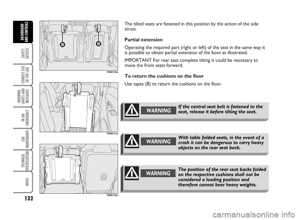
The tilted seats are fastened in this position by the action of the side
struts.
Partial extension
Operating the required part (right or left) of the seat in the same way it
is possible to obtain partial extension of the boot as illustrated.
IMPORTANT For rear seat complete tilting it could be necessary to
move the front seats forward.
To return the cushions on the floor
Use tapes (B) to return the cushions on the floor.
132
SAFETY
DEVICES
CORRECT USE
OF THE CAR
WARNING
LIGHTS AND
MESSAGES
IN AN
EMERGENCY
CAR
MAINTENANCE
TECHNICAL
SPECIFICATIONS
INDEX
DASHBOARD
AND CONTROLS
F0H0111m
F0H0112m
F0H0110m
With table folded seats, in the event of a
crash it can be dangerous to carry heavy
objects on the rear seat back.WARNING
WARNINGThe position of the rear seat backs folded
on the respective cushions shall not be
considered a loading position and
therefore cannot bear heavy weights.
If the central seat belt is fastened to the
seat, release it before tilting the seat.WARNING
Page 134 of 314
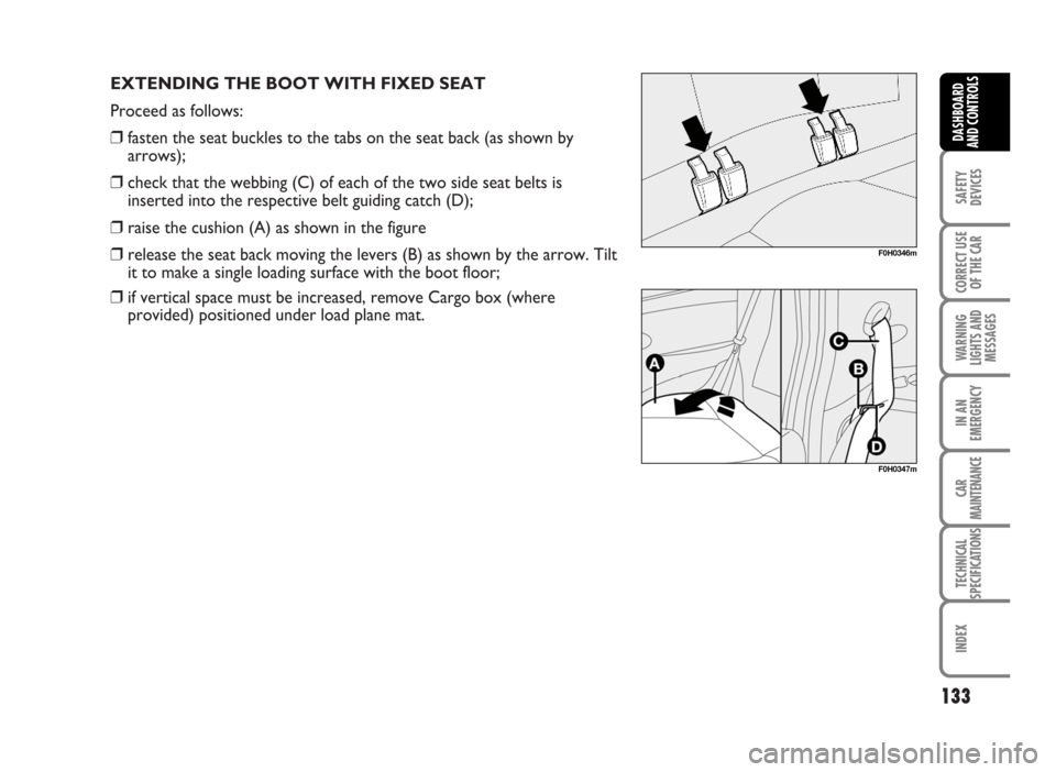
EXTENDING THE BOOT WITH FIXED SEAT
Proceed as follows:
❒fasten the seat buckles to the tabs on the seat back (as shown by
arrows);
❒check that the webbing (C) of each of the two side seat belts is
inserted into the respective belt guiding catch (D);
❒raise the cushion (A) as shown in the figure
❒release the seat back moving the levers (B) as shown by the arrow. Tilt
it to make a single loading surface with the boot floor;
❒if vertical space must be increased, remove Cargo box (where
provided) positioned under load plane mat.
133
SAFETY
DEVICES
CORRECT USE
OF THE CAR
WARNING
LIGHTS AND
MESSAGES
IN AN
EMERGENCY
CAR
MAINTENANCE
TECHNICAL
SPECIFICATIONS
INDEX
DASHBOARD
AND CONTROLS
F0H0346m
F0H0347m