buttons FIAT IDEA 2007 1.G Owners Manual
[x] Cancel search | Manufacturer: FIAT, Model Year: 2007, Model line: IDEA, Model: FIAT IDEA 2007 1.GPages: 314, PDF Size: 4.78 MB
Page 5 of 314
4
SAFETY
DEVICES
CORRECT USE
OF THE CAR
WARNING
LIGHTS AND
MESSAGES
IN AN
EMERGENCY
CAR
MAINTENANCE
TECHNICAL
SPECIFICATIONS
INDEX
DASHBOARD
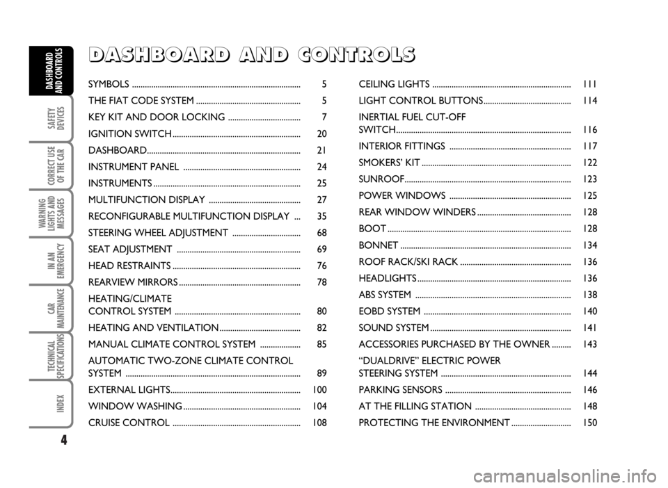
AND CONTROLSSYMBOLS ............................................................................... 5
THE FIAT CODE SYSTEM ................................................. 5
KEY KIT AND DOOR LOCKING .................................. 7
IGNITION SWITCH ............................................................ 20
DASHBOARD........................................................................ 21
INSTRUMENT PANEL ....................................................... 24
INSTRUMENTS ..................................................................... 25
MULTIFUNCTION DISPLAY ........................................... 27
RECONFIGURABLE MULTIFUNCTION DISPLAY ... 35
STEERING WHEEL ADJUSTMENT ................................ 68
SEAT ADJUSTMENT .......................................................... 69
HEAD RESTRAINTS ............................................................ 76
REARVIEW MIRRORS ......................................................... 78
HEATING/CLIMATE
CONTROL SYSTEM ........................................................... 80
HEATING AND VENTILATION ...................................... 82
MANUAL CLIMATE CONTROL SYSTEM ................... 85
AUTOMATIC TWO-ZONE CLIMATE CONTROL
SYSTEM .................................................................................. 89
EXTERNAL LIGHTS............................................................. 100
WINDOW WASHING ....................................................... 104
CRUISE CONTROL ............................................................ 108CEILING LIGHTS ................................................................. 111
LIGHT CONTROL BUTTONS ......................................... 114
INERTIAL FUEL CUT-OFF
SWITCH.................................................................................. 116
INTERIOR FITTINGS ......................................................... 117
SMOKERS’ KIT ...................................................................... 122
SUNROOF.............................................................................. 123
POWER WINDOWS ......................................................... 125
REAR WINDOW WINDERS ............................................ 128
BOOT ...................................................................................... 128
BONNET ................................................................................ 134
ROOF RACK/SKI RACK .................................................... 136
HEADLIGHTS ........................................................................ 136
ABS SYSTEM ......................................................................... 138
EOBD SYSTEM ..................................................................... 140
SOUND SYSTEM .................................................................. 141
ACCESSORIES PURCHASED BY THE OWNER ......... 143
“DUALDRIVE” ELECTRIC POWER
STEERING SYSTEM ............................................................. 144
PARKING SENSORS ........................................................... 146
AT THE FILLING STATION ............................................. 148
PROTECTING THE ENVIRONMENT ............................ 150
D D
A A
S S
H H
B B
O O
A A
R R
D D
A A
N N
D D
C C
O O
N N
T T
R R
O O
L L
S S
Page 14 of 314
13
SAFETY
DEVICES
CORRECT USE
OF THE CAR
WARNING
LIGHTS AND
MESSAGES
IN AN
EMERGENCY
CAR
MAINTENANCE
TECHNICAL
SPECIFICATIONS
INDEX
DASHBOARD
AND CONTROLS
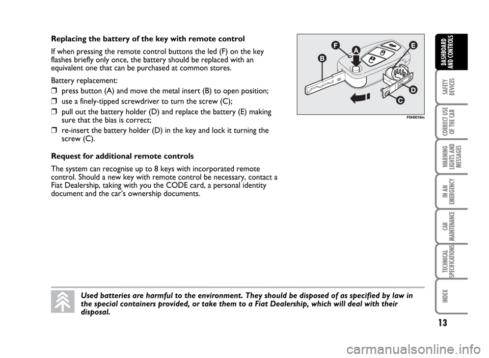
Replacing the battery of the key with remote control
If when pressing the remote control buttons the led (F) on the key
flashes briefly only once, the battery should be replaced with an
equivalent one that can be purchased at common stores.
Battery replacement:
❒press button (A) and move the metal insert (B) to open position;
❒use a finely-tipped screwdriver to turn the screw (C);
❒pull out the battery holder (D) and replace the battery (E) making
sure that the bias is correct;
❒re-insert the battery holder (D) in the key and lock it turning the
screw (C).
Request for additional remote controls
The system can recognise up to 8 keys with incorporated remote
control. Should a new key with remote control be necessary, contact a
Fiat Dealership, taking with you the CODE card, a personal identity
document and the car’s ownership documents.
F0H0018m
Used batteries are harmful to the environment. They should be disposed of as specified by law in
the special containers provided, or take them to a Fiat Dealership, which will deal with their
disposal.
Page 17 of 314
DEAD LOCK DEVICE (where provided)
This safety device enables to inhibit:
❒door internal handles;
❒door locking/unlocking buttons set on the
dashboard;
16
SAFETY
DEVICES
CORRECT USE
OF THE CAR
WARNING
LIGHTS AND
MESSAGES
IN AN
EMERGENCY
CAR
MAINTENANCE
TECHNICAL
SPECIFICATIONS
INDEX
DASHBOARD
AND CONTROLS
Once the dead lock device has been actuated, doors cannot be opened from inside
the car in any way whatsoever. For this reason, make sure there are no persons left
inside the car.WARNING
thus hindering doors opening from inside the
passenger’s compartment in case of attempt to break-
into (e.g. window breaking).
Page 22 of 314
21
SAFETY
DEVICES
CORRECT USE
OF THE CAR
WARNING
LIGHTS AND
MESSAGES
IN AN
EMERGENCY
CAR
MAINTENANCE
TECHNICAL
SPECIFICATIONS
INDEX
DASHBOARD
AND CONTROLS
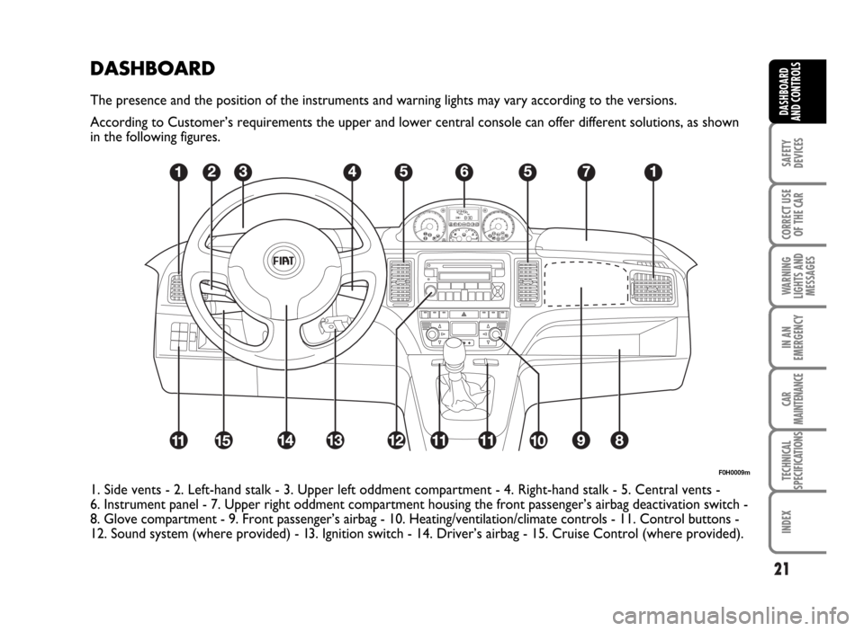
DASHBOARD
The presence and the position of the instruments and warning lights may vary according to the versions.
According to Customer’s requirements the upper and lower central console can offer different solutions, as shown
in the following figures.
F0H0009m
1. Side vents - 2. Left-hand stalk - 3. Upper left oddment compartment - 4. Right-hand stalk - 5. Central vents -
6. Instrument panel - 7. Upper right oddment compartment housing the front passenger’s airbag deactivation switch -
8. Glove compartment - 9. Front passenger’s airbag - 10. Heating/ventilation/climate controls - 11. Control buttons -
12. Sound system (where provided) - 13. Ignition switch - 14. Driver’s airbag - 15. Cruise Control (where provided).
Page 29 of 314
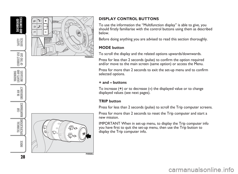
DISPLAY CONTROL BUTTONS
To use the information the “Multifunction display” is able to give, you
should firstly familiarise with the control buttons using them as described
below.
Before doing anything you are advised to read this section thoroughly.
MODE button
To scroll the display and the related options upwards/downwards.
Press for less than 2 seconds (pulse) to confirm the option required
and/or move to the main screen (same option) or access the Menu.
Press for more than 2 seconds to exit the set-up menu and to confirm
selected options.
+ and – buttons
To increase (+) or to decrease (–) the displayed value or to change
displayed values (see next pages).
TRIP button
Press for less than 2 seconds (pulse) to scroll the Trip computer screens.
Press for more than 2 seconds to reset the Trip computer and start a
new mission.
IMPORTANT When in set-up menu, to display the Trip computer info
you have first to quit the set-up menu, then use the Trip button to
display the Trip computer info.
28
SAFETY
DEVICES
CORRECT USE
OF THE CAR
WARNING
LIGHTS AND
MESSAGES
IN AN
EMERGENCY
CAR
MAINTENANCE
TECHNICAL
SPECIFICATIONS
INDEX
DASHBOARD
AND CONTROLS
F0H0025m
FH0026m
Page 30 of 314
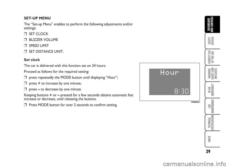
SET-UP MENU
The “Set-up Menu” enables to perform the following adjustments and/or
settings:
❒SET CLOCK
❒BUZZER VOLUME
❒SPEED LIMIT
❒SET DISTANCE UNIT.
Set clock
The car is delivered with this function set on 24 hours.
Proceed as follows for the required setting:
❒press repeatedly the MODE button until displaying “Hour”;
❒press +to increase by one minute;
❒press –to decrease by one minute.
Keeping buttons +or –pressed for a few seconds obtains automatic fast
increase or decrease, until releasing the buttons.
❒Press MODE button for over 2 seconds to confirm setting.
29
SAFETY
DEVICES
CORRECT USE
OF THE CAR
WARNING
LIGHTS AND
MESSAGES
IN AN
EMERGENCY
CAR
MAINTENANCE
TECHNICAL
SPECIFICATIONS
INDEX
DASHBOARD
AND CONTROLS
F0H0034m
Page 33 of 314
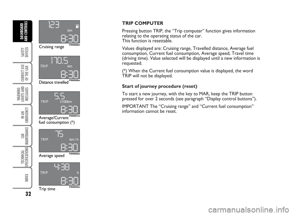
TRIP COMPUTER
Pressing button TRIP, the “Trip computer” function gives information
relating to the operating status of the car.
This function is resettable.
Values displayed are: Cruising range, Travelled distance, Average fuel
consumption, Current fuel consumption, Average speed, Travel time
(driving time). Value selected will be displayed until a new information is
requested.
(*) When the Current fuel consumption value is displayed, the word
TRIP will not be displayed.
Start of journey procedure (reset)
To start a new journey, with the key to MAR, keep the TRIP button
pressed for over 2 seconds (see paragraph “Display control buttons”).
IMPORTANT The “Cruising range” and “Current fuel consumption”
information cannot be reset.
32
SAFETY
DEVICES
CORRECT USE
OF THE CAR
WARNING
LIGHTS AND
MESSAGES
IN AN
EMERGENCY
CAR
MAINTENANCE
TECHNICAL
SPECIFICATIONS
INDEX
DASHBOARD
AND CONTROLS
F0H0029m
F0H0031m
F0H0030m
F0H0032m
F0H0033m
Cruising range
Average/Current
fuel consumption (*) Distance travelled
Average speed
Trip time
Page 34 of 314
Cruising range= shows the distance (in km or
miles) that the car can still cover before needing fuel,
assuming that driving conditions are kept unvaried.
The display will show “- - - -” in the following cases:
❒value for range to empty lower than 50 km or fuel
level below 4 litres; in this event before “- - - -”
the message “Warning, limited range” will be
displayed (this message will be displayed also if not
in TRIP COMPUTER mode);
❒in case of car parked with engine running for a
long period, when the car moves off the range to
empty indication will be displayed again.
Travelled distance= shows the km (or miles)
covered from last reset (*).
Average fuel consumption= shows the average
consumption calculated from last reset (*), this value
can be expressed in l/100 km or mpg.
Instant consumption= shows the fuel consumption
variation updated every second, it can be expressed in
l/100 km or mpg. In case of car parked with engine
running the display will show “- - - -”. When the car
moves off the instant consumption indication will be
displayed again.
Average speed= shows the average speed of the
car in relation with total time elapsed from last reset
(*), this value can be expressed in km/h or in mph.Travel time= time elapsed from last reset (*).
(*) Reset can be:
– “manual”, reset is performed by the driver by
pressing the relevant button (see paragraph
“Control buttons”)
– “automatic”, reset is performed when the travelled
distance reaches 3999.9 km or when travel time
reaches 99:59 (99 hours and 59 minutes)
– after reconnecting the battery.
IMPORTANT Lacking information, Trip computer
values are displayed with “- - - -”. When restoring
normal operating conditions after a failure, calculation
will restart regularly without resetting values.
IMPORTANT After battery disconnection/connection
certain displayed values are equal to “- - - -” until
significant data for calculation are available.
33
SAFETY
DEVICES
CORRECT USE
OF THE CAR
WARNING
LIGHTS AND
MESSAGES
IN AN
EMERGENCY
CAR
MAINTENANCE
TECHNICAL
SPECIFICATIONS
INDEX
DASHBOARD
AND CONTROLS
Page 37 of 314
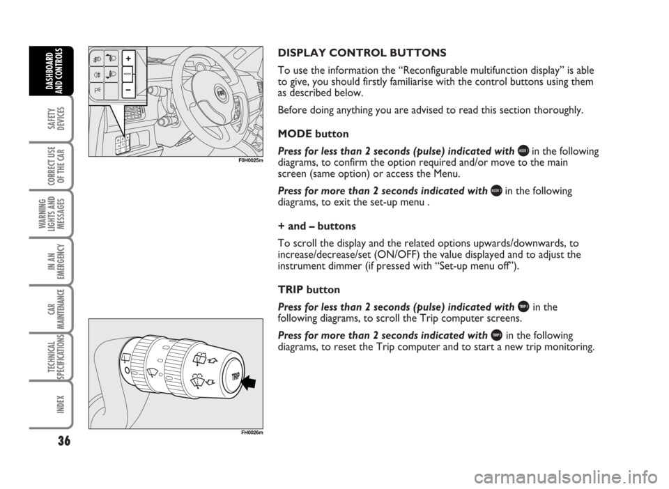
DISPLAY CONTROL BUTTONS
To use the information the “Reconfigurable multifunction display” is able
to give, you should firstly familiarise with the control buttons using them
as described below.
Before doing anything you are advised to read this section thoroughly.
MODE button
Press for less than 2 seconds (pulse) indicated with
bin the following
diagrams, to confirm the option required and/or move to the main
screen (same option) or access the Menu.
Press for more than 2 seconds indicated with
cin the following
diagrams, to exit the set-up menu .
+ and – buttons
To scroll the display and the related options upwards/downwards, to
increase/decrease/set (ON/OFF) the value displayed and to adjust the
instrument dimmer (if pressed with “Set-up menu off”).
TRIP button
Press for less than 2 seconds (pulse) indicated with
%in the
following diagrams, to scroll the Trip computer screens.
Press for more than 2 seconds indicated with
&in the following
diagrams, to reset the Trip computer and to start a new trip monitoring.
36
SAFETY
DEVICES
CORRECT USE
OF THE CAR
WARNING
LIGHTS AND
MESSAGES
IN AN
EMERGENCY
CAR
MAINTENANCE
TECHNICAL
SPECIFICATIONS
INDEX
DASHBOARD
AND CONTROLS
F0H0025m
FH0026m
Page 39 of 314
SET-UP MENU
The “Set-up Menu” enables to perform the following
adjustments and/or settings using the control buttons
(see previous pages):
❒SPEED LIMIT
❒AUTOMATIC HEADLIGHT DAYLIGHT SENSOR
(where provided)
❒TRIP B ON/OFF
❒SET CLOCK
❒CLOCK MODE
❒SET DATE
❒SPEEDLOCK
❒INDEPENDENT BOOT
❒DRIVER’S DOOR UNLOCKING❒DISTANCE UNIT
❒CONSUMPTION UNIT
❒TEMPERATURE UNIT (where required)
❒LANGUAGE
❒BUZZER VOLUME
❒BUTTON VOLUME
❒S.B.R. (Seat Belt Reminder) BUZZER
REACTIVATION (*)
❒SERVICE
❒EXIT MENU
38
SAFETY
DEVICES
CORRECT USE
OF THE CAR
WARNING
LIGHTS AND
MESSAGES
IN AN
EMERGENCY
CAR
MAINTENANCE
TECHNICAL
SPECIFICATIONS
INDEX
DASHBOARD
AND CONTROLS
(*) This function can be displayed only after Fiat Dealership has deactivated the S.B.R. system.