Indicator FIAT IDEA 2008 1.G Owners Manual
[x] Cancel search | Manufacturer: FIAT, Model Year: 2008, Model line: IDEA, Model: FIAT IDEA 2008 1.GPages: 210, PDF Size: 3.64 MB
Page 14 of 210
13
SAFETY
DEVICES
CORRECT USE
OF THE CAR
WARNING
LIGHTS AND
MESSAGES
IN AN
EMERGENCY
CAR
MAINTENANCE
TECHNICAL
SPECIFICATIONS
INDEX
DASHBOARD
AND CONTROLS
fig. 16F0H0702m
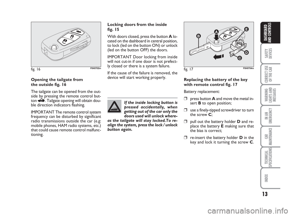
Opening the tailgate from
the outside fig. 16
The tailgate can be opened from the out-
side by pressing the remote control but-
ton
R. Tailgate opening will obtain dou-
ble direction indicators flashing.
IMPORTANT The remote control system
frequency can be disturbed by significant
radio transmissions outside the car (e.g:
mobile phones, HAM radio systems, etc.)
that could cause remote control malfunc-
tioning.Locking doors from the inside
fig. 15
With doors closed, press the button Alo-
cated on the dashboard in central position,
to lock (led on the button ON) or unlock
(led on the button OFF) the doors.
IMPORTANT Door locking from inside
will not cut-in if one door is not prefect-
ly closed or there is a system failure.
If the cause of the failure is removed, the
device will start working properly.
If the inside locking button is
pressed accidentally, when
getting out of the car only the
doors used will unlock where-
as the tailgate will stay locked.To re-
align the system, press the lock / unlock
button again.
fig. 17F0H0704m
Replacing the battery of the key
with remote control fig. 17
Battery replacement:
❒press button Aand move the metal in-
sert Bto open position;
❒use a finely-tipped screwdriver to turn
the screw C;
❒pull out the battery holder Dand re-
place the battery Emaking sure that
the bias is correct;
❒re-insert the battery holder Din the
key and lock it turning the screw C.
001-035 idea GB 1 ed 10-07-2008 8:27 Pagina 13
Page 17 of 210
16
SAFETY
DEVICES
CORRECT USE
OF THE CAR
WARNING
LIGHTS AND
MESSAGES
IN AN
EMERGENCY
CAR
MAINTENANCE
TECHNICAL
SPECIFICATIONS
INDEX
DASHBOARD
AND CONTROLSType ofkey
Pressing the pushbutton Ëenables fuel lid to be opened.
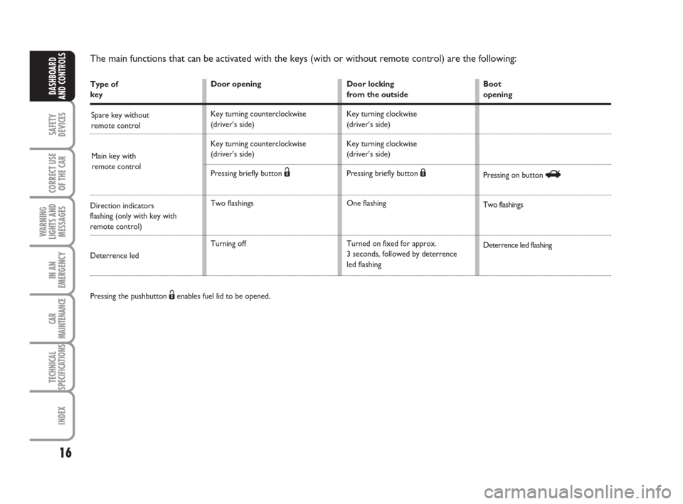
The main functions that can be activated with the keys (with or without remote control) are the following:
Door opening
Key turning counterclockwise
(driver’s side)
Key turning counterclockwise
(driver’s side)
Pressing briefly button
Ë
Two flashings
Turning off Door locking
from the outside
Key turning clockwise
(driver’s side)
Key turning clockwise
(driver’s side)
Pressing briefly button
Á
One flashing
Turned on fixed for approx.
3 seconds, followed by deterrence
led flashingBoot
opening
Pressing on button
R
Two flashings
Deterrence led flashing Spare key without
remote control
Main key with
remote control
Direction indicators
flashing (only with key with
remote control)
Deterrence led
001-035 idea GB 1 ed 10-07-2008 8:27 Pagina 16
Page 20 of 210
19
SAFETY
DEVICES
CORRECT USE
OF THE CAR
WARNING
LIGHTS AND
MESSAGES
IN AN
EMERGENCY
CAR
MAINTENANCE
TECHNICAL
SPECIFICATIONS
INDEX
DASHBOARD
AND CONTROLS
INSTRUMENTS
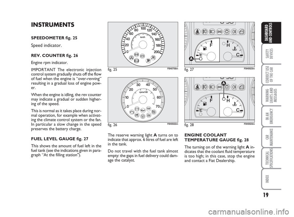
SPEEDOMETER fig. 25
Speed indicator.
REV. COUNTER fig. 26
Engine rpm indicator.
IMPORTANT The electronic injection
control system gradually shuts off the flow
of fuel when the engine is “over-revving”
resulting in a gradual loss of engine pow-
er.
When the engine is idling, the rev counter
may indicate a gradual or sudden higher-
ing of the speed.
This is normal as it takes place during nor-
mal operation, for example when activat-
ing the climate control system or the fan.
In particular a slow change in the speed
preserves the battery charge.
FUEL LEVEL GAUGE fig. 27
This shows the amount of fuel left in the
fuel tank (see the indications given in para-
graph “At the filling station").
fig. 25F0H0708m
fig. 26F0H0022m
fig. 27F0H0023m
fig. 28F0H0024m
The reserve warning light Aturns on to
indicate that approx. 6 litres of fuel are left
in the tank.
Do not travel with the fuel tank almost
empty: the gaps in fuel delivery could dam-
age the catalyst.ENGINE COOLANT
TEMPERATURE GAUGE fig. 28
The turning on of the warning light Ain-
dicates that the coolant fluid temperature
is too high; in this case, stop the engine
and contact a Fiat Dealership.
001-035 idea GB 1 ed 10-07-2008 8:27 Pagina 19
Page 60 of 210
59
SAFETY
DEVICES
CORRECT USE
OF THE CAR
WARNING
LIGHTS AND
MESSAGES
IN AN
EMERGENCY
CAR
MAINTENANCE
TECHNICAL
SPECIFICATIONS
INDEX
DASHBOARD
AND CONTROLS
fig. 70F0H0071mfig. 71F0H0070mfig. 72F0H0072m
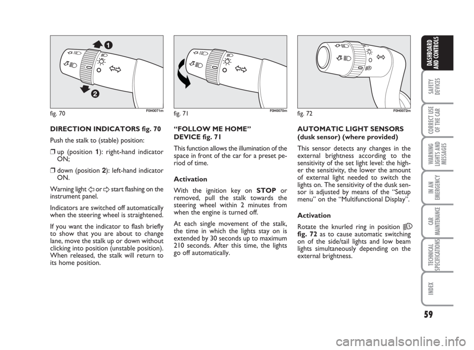
DIRECTION INDICATORS fig. 70
Push the stalk to (stable) position:
❒up (position 1): right-hand indicator
ON;
❒down (position 2): left-hand indicator
ON.
Warning light
For Dstart flashing on the
instrument panel.
Indicators are switched off automatically
when the steering wheel is straightened.
If you want the indicator to flash briefly
to show that you are about to change
lane, move the stalk up or down without
clicking into position (unstable position).
When released, the stalk will return to
its home position.“FOLLOW ME HOME”
DEVICE fig. 71
This function allows the illumination of the
space in front of the car for a preset pe-
riod of time.
Activation
With the ignition key on STOPor
removed, pull the stalk towards the
steering wheel within 2 minutes from
when the engine is turned off.
At each single movement of the stalk,
the time in which the lights stay on is
extended by 30 seconds up to maximum
210 seconds. After this time, the lights
go off automatically. AUTOMATIC LIGHT SENSORS
(dusk sensor) (where provided)
This sensor detects any changes in the
external brightness according to the
sensitivity of the set light level: the high-
er the sensitivity, the lower the amount
of external light needed to switch the
lights on. The sensitivity of the dusk sen-
sor is adjusted by means of the “Setup
menu” on the “Multifunctional Display”.
Activation
Rotate the knurled ring in position
2A
fig. 72as to cause automatic switching
on of the side/tail lights and low beam
lights simultaneously depending on the
external brightness.
036-092 idea GB 1 ed 10-07-2008 16:12 Pagina 59
Page 77 of 210
76
SAFETY
DEVICES
CORRECT USE
OF THE CAR
WARNING
LIGHTS AND
MESSAGES
IN AN
EMERGENCY
CAR
MAINTENANCE
TECHNICAL
SPECIFICATIONS
INDEX
DASHBOARD
AND CONTROLS
BOOT
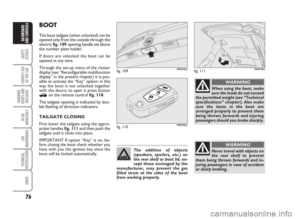
The boot tailgate (when unlocked) can be
opened only from the outside through the
electric fig. 109opening handle set above
the number plate holder.
If doors are unlocked the boot can be
opened at any time.
Through the set-up menu of the cluster
display (see “Reconfigurable multifunction
display” in the present chapter) it is pos-
sible to activate the “Key” option: in this
way the boot is not unlocked together
with the doors; to open it press button
Ron the remote control fig. 110.
The tailgate opening is indicated by dou-
ble flashing of direction indicators.
TAILGATE CLOSING
First lower the tailgate using the appro-
priate handles fig. 111and then push the
tailgate until it clicks into place.
IMPORTANT If option “Key” is on, be-
fore closing the boot check whether you
have with you the ignition key since the
boot will be locked automatically.
fig. 109F0H0742m
fig. 110F0H0702m
The addition of objects
(speakers, spoilers, etc.) on
the rear shelf or boot lid, ex-
cept those envisaged by the
manufacturer, may prevent the gas
filled struts at the sides of the boot
from working properly.
When using the boot, make
sure the loads do not exceed
the permitted weight (see “Technical
specifications” chapter). Also make
sure the items in the boot are
arranged properly to prevent them
being thrown forwards and injuring
passengers should you brake sharply.
WARNING
Never travel with objects on
the rear shelf to prevent
them being thrown forwards and in-
juring passengers in case of accident
or sharp braking.
WARNING
fig. 111F0H0105m
036-092 idea GB 1 ed 10-07-2008 16:12 Pagina 76
Page 123 of 210
122
WARNING
LIGHTS AND
MESSAGES
IN AN
EMERGENCY
CAR
MAINTENANCE
TECHNICAL
SPECIFICATIONS
INDEX
DASHBOARD
AND CONTROLS
SAFETY
DEVICES
CORRECT USE
OF THE CAR
CAR INACTIVITY
If the car is to be left inactive for longer
than a month, the following precautions
should be noted:
❒park the car in covered, dry and if pos-
sible well-ventilated premises;
❒engage a gear;
❒check that the handbrake is not en-
gaged;
❒disconnect battery terminals (first dis-
connect the negative terminal) and
check the battery charge. This check
is to be repeated every three months
when the car is left inactive. Recharge
if the optical indicator shows a dark
colour without the central green area;
❒clean and protect the painted parts us-
ing protective wax;
❒clean and protect the shiny metal
parts using special compounds readi-
ly available;
❒sprinkle talcum powder on the rub-
ber windscreen and rear window
wiper blades and lift them off the
glass;
❒slightly open the windows;
❒cover the car with a cloth or perfo-
rated plastic sheet. Do not use sheets
of non-perforated plastic as they do
not allow moisture on the car body to
evaporate;
❒inflate tyres to +0.5 bar above the
normal specified pressure and check it
at intervals;
❒if you don’t disconnect the battery
from the electric system, check its
charge every month and recharge it if
the optical indicator shows a dark
colour without the central green area;
❒do not drain the engine cooling sys-
tem.
111-122 idea GB 1 ed 10-07-2008 8:29 Pagina 122
Page 124 of 210
123
IN AN
EMERGENCY
CAR
MAINTENANCE
TECHNICAL
SPECIFICATIONS
INDEX
DASHBOARD
AND CONTROLS
SAFETY
DEVICES
CORRECT USE
OF THE CAR
WARNING
LIGHTS AND
MESSAGES
GENERAL WARNINGS ...................................................... 124
LOW BRAKE FLUID LEVEL .............................................. 124
HANDBRAKE ON ............................................................... 124
AIRBAG FAILURE ................................................................. 124
HOT ENGINE COOLANT ................................................ 125
LOW BATTERY CHARGE................................................. 125
LOW ENGINE OIL PRESSURE ......................................... 126
EXHAUSTED OIL ................................................................. 126
“DUALDRIVE” ELECTRIC POWER
STEERING FAILURE............................................................. 126
INCOMPLETE DOOR LOCKING ................................... 126
SEAT BELTS NOT FASTENED ......................................... 126
EBD FAILURE......................................................................... 127
INJECTION SYSTEM FAILURE ......................................... 127
EOBD ENGINE CONTROL SYSTEM FAILURE ........... 127
FRONT PASSENGER AIRBAG DISABLED .................... 128
ABS SYSTEM FAILURE ........................................................ 128
FUEL RESERVE....................................................................... 128
GLOW PLUG HEATING.................................................... 129
GLOW PLUG HEATING FAILURE.................................. 129
WATER IN DIESEL FUEL FILTER ..................................... 129
CAR PROTECTION SYSTEM FAULT - FIAT CODE .. 129
REAR FOG LIGHTS ............................................................. 129
GENERAL FAILURE INDICATION ................................. 130
WW W
A A
R R
N N
I I
N N
G G
L L
I I
G G
H H
T T
S S
A A
N N
D D
M M
E E
S S
S S
A A
G G
E E E
S S
BRAKE PAD WEAR ............................................................. 131
PARTICULATE FILTER CLOGGED................................. 131
SIDE/TAIL LIGHTS AND LOW BEAMS ......................... 131
FOLLOW ME HOME ......................................................... 131
FRONT FOG LIGHTS ......................................................... 131
LEFT-HAND DIRECTION INDICATOR ....................... 132
RIGHT-HAND DIRECTION INDICATOR ................... 132
“DUALDRIVE” ELECTRIC POWER STEERING
ACTIVATION ........................................................................ 132
CRUISE CONTROL SYSTEM ............................................ 132
MAIN BEAMS ......................................................................... 132
POSSIBLE ICE ON ROAD.................................................. 132
LIMITED RANGE .................................................................. 132
123-132 idea GB 1 ed 10-07-2008 8:29 Pagina 123
Page 131 of 210
130
IN AN
EMERGENCY
CAR
MAINTENANCE
TECHNICAL
SPECIFICATIONS
INDEX
DASHBOARD
AND CONTROLS
SAFETY
DEVICES
CORRECT USE
OF THE CAR
WARNING
LIGHTS AND
MESSAGES
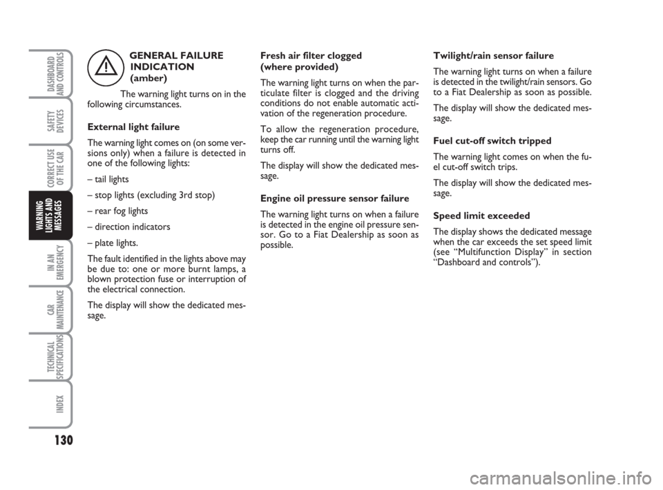
GENERAL FAILURE
INDICATION
(amber)
The warning light turns on in the
following circumstances.
External light failure
The warning light comes on (on some ver-
sions only) when a failure is detected in
one of the following lights:
– tail lights
– stop lights (excluding 3rd stop)
– rear fog lights
– direction indicators
– plate lights.
The fault identified in the lights above may
be due to: one or more burnt lamps, a
blown protection fuse or interruption of
the electrical connection.
The display will show the dedicated mes-
sage.
è
Fresh air filter clogged
(where provided)
The warning light turns on when the par-
ticulate filter is clogged and the driving
conditions do not enable automatic acti-
vation of the regeneration procedure.
To allow the regeneration procedure,
keep the car running until the warning light
turns off.
The display will show the dedicated mes-
sage.
Engine oil pressure sensor failure
The warning light turns on when a failure
is detected in the engine oil pressure sen-
sor. Go to a Fiat Dealership as soon as
possible.Twilight/rain sensor failure
The warning light turns on when a failure
is detected in the twilight/rain sensors. Go
to a Fiat Dealership as soon as possible.
The display will show the dedicated mes-
sage.
Fuel cut-off switch tripped
The warning light comes on when the fu-
el cut-off switch trips.
The display will show the dedicated mes-
sage.
Speed limit exceeded
The display shows the dedicated message
when the car exceeds the set speed limit
(see “Multifunction Display” in section
“Dashboard and controls”).
123-132 idea GB 1 ed 10-07-2008 8:29 Pagina 130
Page 133 of 210
132
IN AN
EMERGENCY
CAR
MAINTENANCE
TECHNICAL
SPECIFICATIONS
INDEX
DASHBOARD
AND CONTROLS
SAFETY
DEVICES
CORRECT USE
OF THE CAR
WARNING
LIGHTS AND
MESSAGES
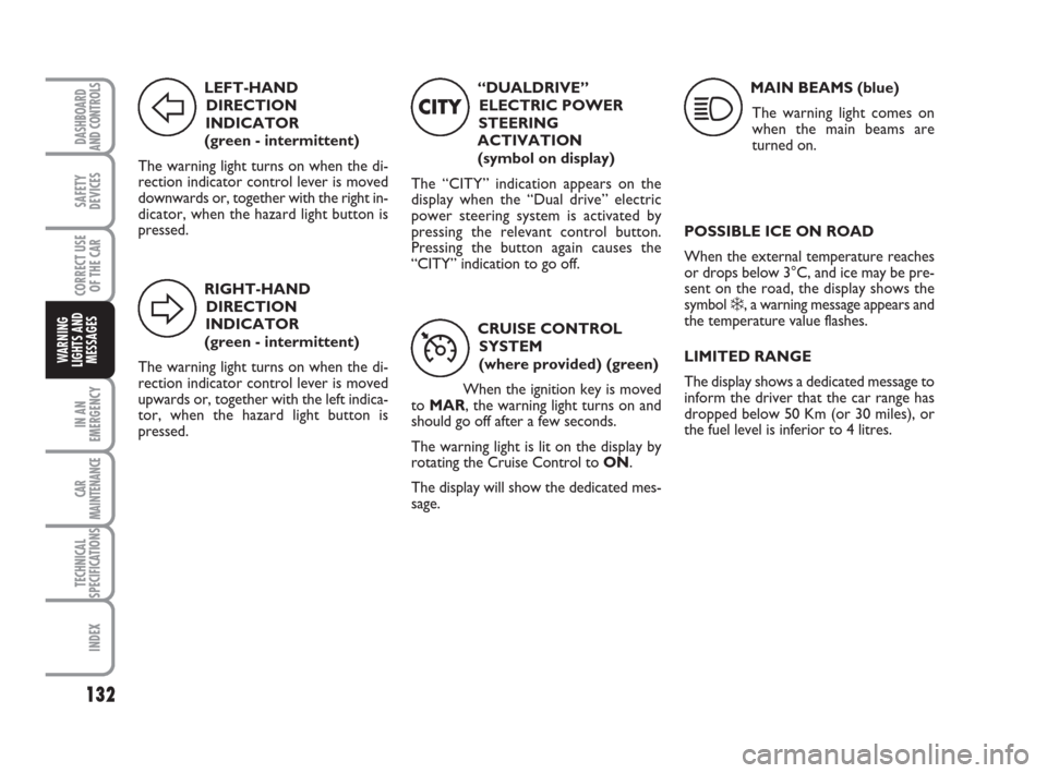
LEFT-HAND
DIRECTION
INDICATOR
(green - intermittent)
The warning light turns on when the di-
rection indicator control lever is moved
downwards or, together with the right in-
dicator, when the hazard light button is
pressed.
F
RIGHT-HAND
DIRECTION
INDICATOR
(green - intermittent)
The warning light turns on when the di-
rection indicator control lever is moved
upwards or, together with the left indica-
tor, when the hazard light button is
pressed.
D
“DUALDRIVE”
ELECTRIC POWER
STEERING
ACTIVATION
(symbol on display)
The “CITY” indication appears on the
display when the “Dual drive” electric
power steering system is activated by
pressing the relevant control button.
Pressing the button again causes the
“CITY” indication to go off.
CITY
CRUISE CONTROL
SYSTEM
(where provided) (green)
When the ignition key is moved
to MAR, the warning light turns on and
should go off after a few seconds.
The warning light is lit on the display by
rotating the Cruise Control to ON.
The display will show the dedicated mes-
sage.
Ü
MAIN BEAMS (blue)
The warning light comes on
when the main beams are
turned on.
1
POSSIBLE ICE ON ROAD
When the external temperature reaches
or drops below 3°C, and ice may be pre-
sent on the road, the display shows the
symbol
❄, a warning message appears and
the temperature value flashes.
LIMITED RANGE
The display shows a dedicated message to
inform the driver that the car range has
dropped below 50 Km (or 30 miles), or
the fuel level is inferior to 4 litres.
123-132 idea GB 1 ed 10-07-2008 8:29 Pagina 132
Page 147 of 210
146
CAR
MAINTENANCE
TECHNICAL
SPECIFICATIONS
INDEX
DASHBOARD
AND CONTROLS
SAFETY
DEVICES
CORRECT USE
OF THE CAR
WARNING
LIGHTS AND
MESSAGES
IN AN
EMERGENCY
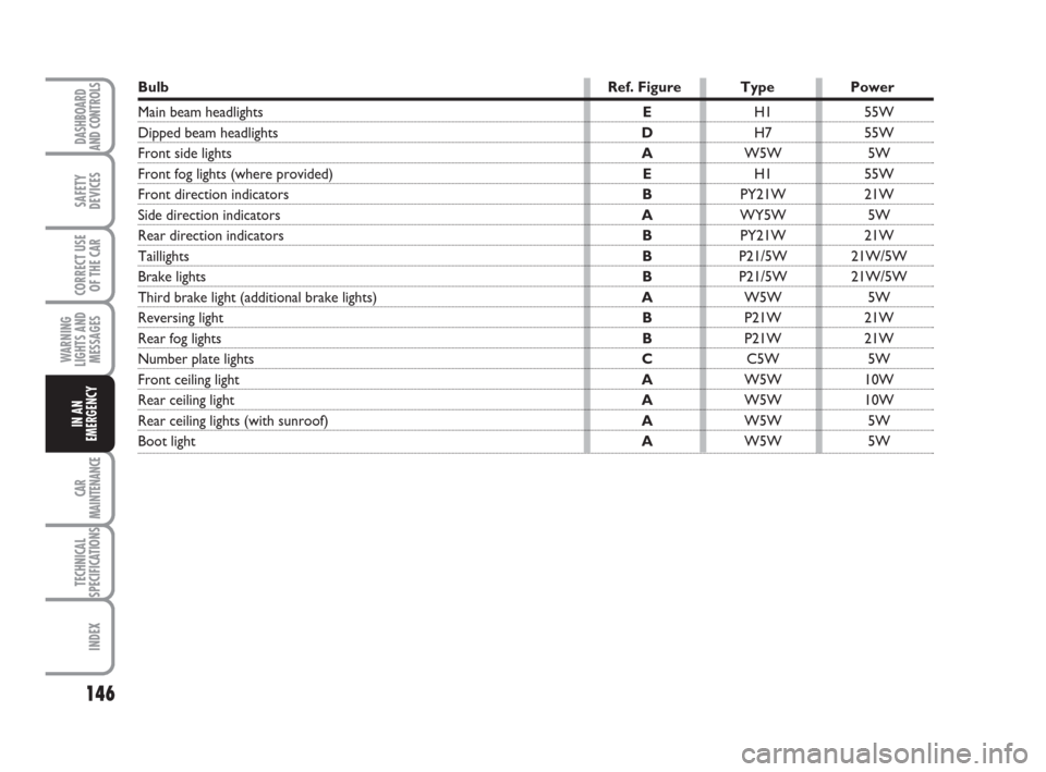
Bulb Ref. Figure Type Power
Main beam headlightsEH1 55W
Dipped beam headlights DH7 55W
Front side lights AW5W 5W
Front fog lights (where provided)EH1 55W
Front direction indicators BPY21W 21W
Side direction indicators AWY5W 5W
Rear direction indicators BPY21W 21W
Taillights BP21/5W 21W/5W
Brake lights BP21/5W 21W/5W
Third brake light (additional brake lights) AW5W 5W
Reversing light BP21W 21W
Rear fog lights BP21W 21W
Number plate lights CC5W 5W
Front ceiling lightAW5W 10W
Rear ceiling lightAW5W 10W
Rear ceiling lights (with sunroof)AW5W 5W
Boot light AW5W 5W
133-160 idea GB 1 ed 10-07-2008 8:30 Pagina 146