power steering FIAT IDEA 2008 1.G Owners Manual
[x] Cancel search | Manufacturer: FIAT, Model Year: 2008, Model line: IDEA, Model: FIAT IDEA 2008 1.GPages: 210, PDF Size: 3.64 MB
Page 5 of 210
4
SAFETY
DEVICES
CORRECT USE
OF THE CAR
WARNING
LIGHTS AND
MESSAGES
IN AN
EMERGENCY
CAR
MAINTENANCE
TECHNICAL
SPECIFICATIONS
INDEX
DASHBOARD
AND CONTROLSDASHBOARD........................................................................ 5
INSTRUMENT PANEL ....................................................... 7
SYMBOLS ............................................................................... 9
THE FIAT CODE SYSTEM ................................................. 9
KEY KIT AND DOOR LOCKING .................................. 10
IGNITION SWITCH ............................................................ 18
INSTRUMENTS ..................................................................... 19
MULTIFUNCTION DISPLAY ........................................... 20
RECONFIGURABLE MULTIFUNCTION DISPLAY ... 23
ADJUSTMENT OF THE WHEEL ...................................... 36
ADJUSTMENT OF THE SEATS ......................................... 36
HEAD RESTRAINTS ............................................................ 41
REARVIEW MIRRORS ......................................................... 42
HEATING/CLIMATE
CONTROL SYSTEM ........................................................... 44
HEATING AND VENTILATION ...................................... 45
MANUAL CLIMATE CONTROL SYSTEM ................... 48
AUTOMATIC TWO-ZONE CLIMATE
CONTROL SYSTEM ........................................................... 51
EXTERNAL LIGHTS............................................................. 58
WINDOW WASHING ....................................................... 60
CRUISE CONTROL ............................................................ 63CEILING LIGHTS ................................................................. 64
LIGHT CONTROL BUTTONS ......................................... 66
INERTIAL FUEL CUT- OFF SWITCH ............................. 67
INTERIOR FITTINGS ......................................................... 68
SMOKERS’ KIT ...................................................................... 71
SUNROOF.............................................................................. 72
POWER WINDOWS ......................................................... 74
REAR WINDOW WINDERS ............................................ 75
BOOT ...................................................................................... 76
BONNET ................................................................................ 80
ROOF RACK/SKI RACK .................................................... 81
HEADLIGHTS ........................................................................ 82
ABS SYSTEM ......................................................................... 83
EOBD SYSTEM ..................................................................... 84
SOUND SYSTEM .................................................................. 85
ACCESSORIES PURCHASED BY THE OWNER ......... 86
“DUALDRIVE” ELECTRIC POWER
STEERING SYSTEM ............................................................. 87
PARKING SENSORS ........................................................... 88
AT THE FILLING STATION ............................................. 90
PROTECTING THE ENVIRONMENT ............................ 92
DD D
A A
S S
H H
B B
O O
A A
R R
D D
A A
N N
D D
C C
O O
N N
T T
R R
O O
L L
S S
001-035 idea GB 1 ed 10-07-2008 8:27 Pagina 4
Page 19 of 210
18
SAFETY
DEVICES
CORRECT USE
OF THE CAR
WARNING
LIGHTS AND
MESSAGES
IN AN
EMERGENCY
CAR
MAINTENANCE
TECHNICAL
SPECIFICATIONS
INDEX
DASHBOARD
AND CONTROLS
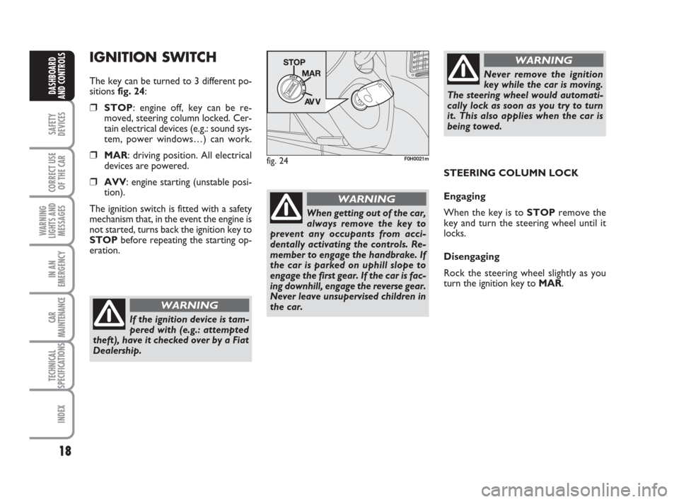
IGNITION SWITCH
The key can be turned to 3 different po-
sitions fig. 24:
❒STOP: engine off, key can be re-
moved, steering column locked. Cer-
tain electrical devices (e.g.: sound sys-
tem, power windows…) can work.
❒MAR: driving position. All electrical
devices are powered.
❒AVV: engine starting (unstable posi-
tion).
The ignition switch is fitted with a safety
mechanism that, in the event the engine is
not started, turns back the ignition key to
STOPbefore repeating the starting op-
eration.
fig. 24F0H0021m
STEERING COLUMN LOCK
Engaging
When the key is to STOPremove the
key and turn the steering wheel until it
locks.
Disengaging
Rock the steering wheel slightly as you
turn the ignition key to MAR.
If the ignition device is tam-
pered with (e.g.: attempted
theft), have it checked over by a Fiat
Dealership.
WARNING
Never remove the ignition
key while the car is moving.
The steering wheel would automati-
cally lock as soon as you try to turn
it. This also applies when the car is
being towed.
WARNING
When getting out of the car,
always remove the key to
prevent any occupants from acci-
dentally activating the controls. Re-
member to engage the handbrake. If
the car is parked on uphill slope to
engage the first gear. If the car is fac-
ing downhill, engage the reverse gear.
Never leave unsupervised children in
the car.
WARNING
001-035 idea GB 1 ed 10-07-2008 8:27 Pagina 18
Page 86 of 210
85
SAFETY
DEVICES
CORRECT USE
OF THE CAR
WARNING
LIGHTS AND
MESSAGES
IN AN
EMERGENCY
CAR
MAINTENANCE
TECHNICAL
SPECIFICATIONS
INDEX
DASHBOARD
AND CONTROLS
SOUND SYSTEM
(where fitted)
For the operation of the radio with CD or
CD MP3, read the instructions for use giv-
en in the attached Supplement.
PRESET SYSTEM (where fitted)
The system consists of:
❒radio power cables
❒front and rear loudspeaker power ca-
bles
❒aerial power cable
❒2 tweeters on front cross members
(power 30W max each);
❒2 mid-woofers on front doors (diam-
eter 165 mm, power 30W max each);
❒2 full-range on rear doors (diameter
165 mm, power 30W max each).
Sound system installation
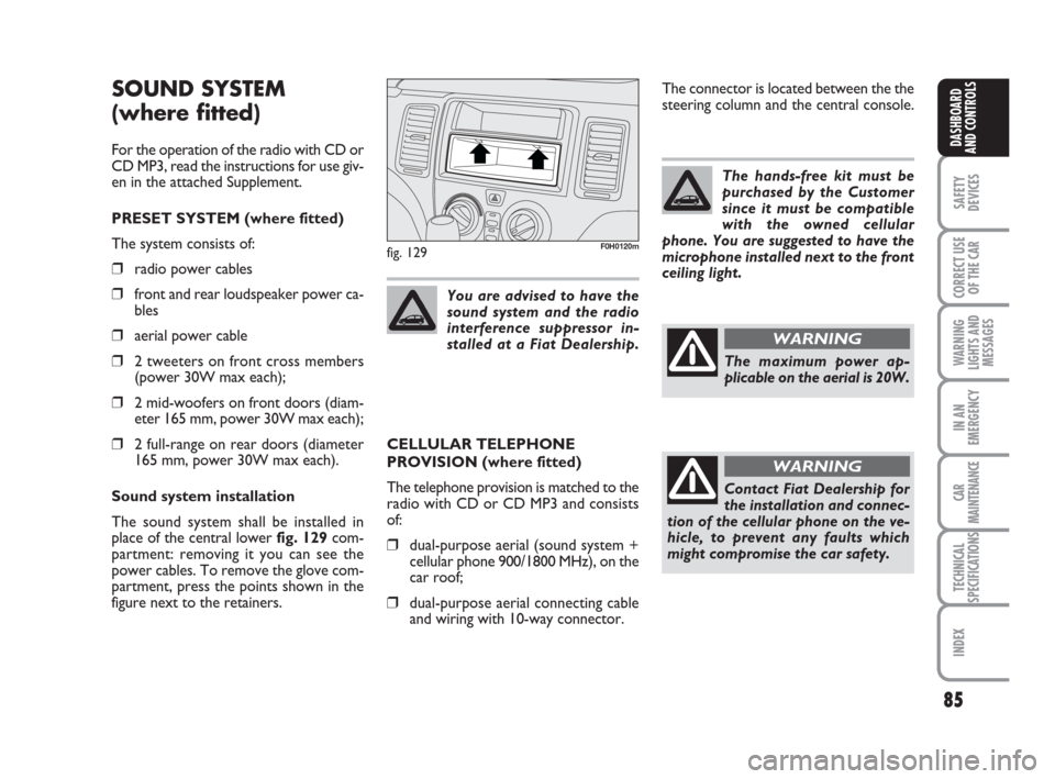
The sound system shall be installed in
place of the central lower fig. 129com-
partment: removing it you can see the
power cables. To remove the glove com-
partment, press the points shown in the
figure next to the retainers.You are advised to have the
sound system and the radio
interference suppressor in-
stalled at a Fiat Dealership.
fig. 129F0H0120m
CELLULAR TELEPHONE
PROVISION (where fitted)
The telephone provision is matched to the
radio with CD or CD MP3 and consists
of:
❒dual-purpose aerial (sound system +
cellular phone 900/1800 MHz), on the
car roof;
❒dual-purpose aerial connecting cable
and wiring with 10-way connector.The hands-free kit must be
purchased by the Customer
since it must be compatible
with the owned cellular
phone. You are suggested to have the
microphone installed next to the front
ceiling light.
The maximum power ap-
plicable on the aerial is 20W.
WARNING
Contact Fiat Dealership for
the installation and connec-
tion of the cellular phone on the ve-
hicle, to prevent any faults which
might compromise the car safety.
WARNING
The connector is located between the the
steering column and the central console.
036-092 idea GB 1 ed 10-07-2008 16:12 Pagina 85
Page 88 of 210
87
SAFETY
DEVICES
CORRECT USE
OF THE CAR
WARNING
LIGHTS AND
MESSAGES
IN AN
EMERGENCY
CAR
MAINTENANCE
TECHNICAL
SPECIFICATIONS
INDEX
DASHBOARD
AND CONTROLS
“DUALDRIVE” ELECTRIC
POWER STEERING
SYSTEM
The car is fitted with an electrically con-
trolled power steering called “Dualdrive”.
It only works when the ignition key is at
MARand the engine is running and it can
be customised by the driver according to
the driving conditions.
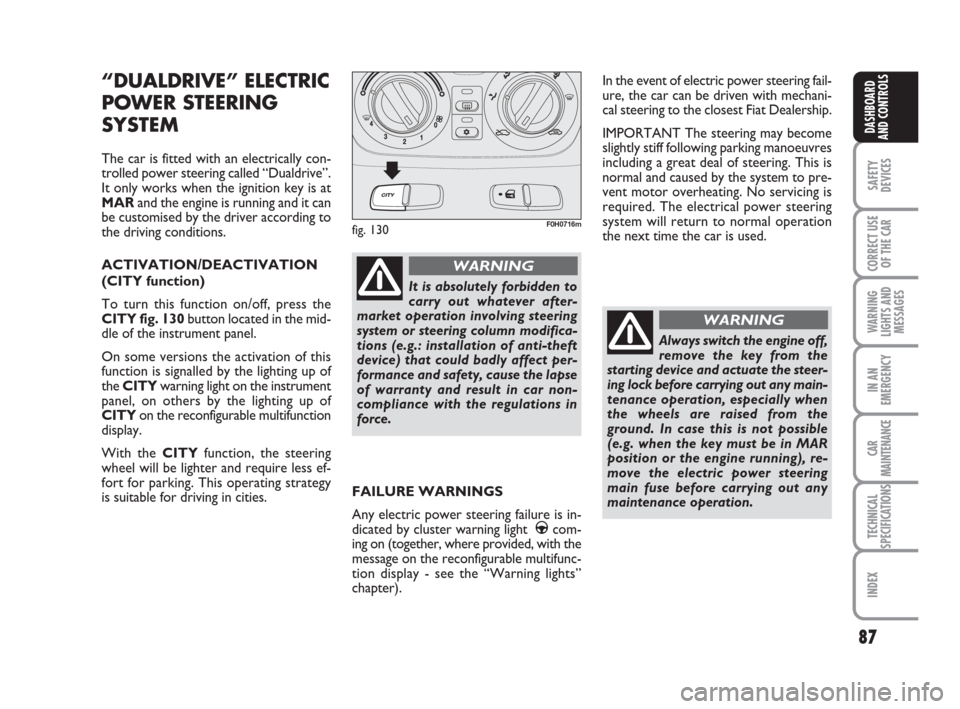
ACTIVATION/DEACTIVATION
(CITY function)
To turn this function on/off, press the
CITY fig. 130button located in the mid-
dle of the instrument panel.
On some versions the activation of this
function is signalled by the lighting up of
the CITYwarning light on the instrument
panel, on others by the lighting up of
CITYon the reconfigurable multifunction
display.
With the CITYfunction, the steering
wheel will be lighter and require less ef-
fort for parking. This operating strategy
is suitable for driving in cities.
fig. 130F0H0716m
It is absolutely forbidden to
carry out whatever after-
market operation involving steering
system or steering column modifica-
tions (e.g.: installation of anti-theft
device) that could badly affect per-
formance and safety, cause the lapse
of warranty and result in car non-
compliance with the regulations in
force.
WARNING
In the event of electric power steering fail-
ure, the car can be driven with mechani-
cal steering to the closest Fiat Dealership.
IMPORTANT The steering may become
slightly stiff following parking manoeuvres
including a great deal of steering. This is
normal and caused by the system to pre-
vent motor overheating. No servicing is
required. The electrical power steering
system will return to normal operation
the next time the car is used.
Always switch the engine off,
remove the key from the
starting device and actuate the steer-
ing lock before carrying out any main-
tenance operation, especially when
the wheels are raised from the
ground. In case this is not possible
(e.g. when the key must be in MAR
position or the engine running), re-
move the electric power steering
main fuse before carrying out any
maintenance operation.
WARNING
FAILURE WARNINGS
Any electric power steering failure is in-
dicated by cluster warning light
gcom-
ing on (together, where provided, with the
message on the reconfigurable multifunc-
tion display - see the “Warning lights”
chapter).
036-092 idea GB 1 ed 10-07-2008 16:12 Pagina 87
Page 114 of 210
113
WARNING
LIGHTS AND
MESSAGES
IN AN
EMERGENCY
CAR
MAINTENANCE
TECHNICAL
SPECIFICATIONS
INDEX
DASHBOARD
AND CONTROLS
SAFETY
DEVICES
CORRECT USE
OF THE CAR
❒Turn the ignition key to AVVas soon
as warning light m goes out. If you wait
too long you will lose the benefit of
the work done by the glow plugs. Re-
lease the key as soon as the engine
starts.
IMPORTANT With cold engine, the ac-
celerator pedal shall be completely re-
leased while turning the ignition key to
AVV.
If the engine does not start at the first at-
tempt, return the ignition key to STOP
before repeating starting.
If, when the ignition key is on MAR, warn-
ing light
Yremains lit, turn the key to
STOPand then back to MAR; if the
warning light remains on, try with the oth-
er keys provided with the car.
If you still cannot start the engine, contact
Fiat Dealership.
IMPORTANT Never leave the ignition key
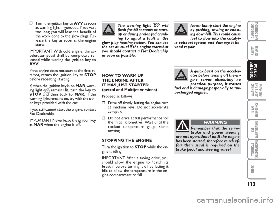
at MARwhen the engine is off.The warning light
mwill
flash for 60 seconds at start-
up or during prolonged crank-
ing to signal a fault in the
glow plug heating system. You can use
the car as usual if the engine starts but
you should contact a Fiat Dealership
as soon as possible.
HOW TO WARM UP
THE ENGINE AFTER
IT HAS JUST STARTED
(petrol and Multijet versions)
Proceed as follows:
❒Drive off slowly, letting the engine turn
at medium revs. Do not accelerate
abruptly;
❒Do not drive at full performance for
the initial kilometres. Wait until the
coolant temperature gauge starts
moving.
STOPPING THE ENGINE
Turn the ignition to STOPwhile the en-
gine is idling.
IMPORTANT After a taxing drive, you
should allow the engine to “catch its
breath” before turning it off by letting it
idle to allow the temperature in the en-
gine compartment to fall.Never bump start the engine
by pushing, towing or coast-
ing downhill. This could cause
fuel to flow into the catalyt-
ic exhaust system and damage it be-
yond repair.
A quick burst on the acceler-
ator before turning off the en-
gine serves absolutely no
practical purpose, it wastes
fuel and is damaging especially to tur-
bocharged engines.
Remember that the servo-
brake and power steering
are not operational until the engine
has been started, therefore much ef-
fort than usual is required on the
brake pedal and steering wheel.
WARNING
111-122 idea GB 1 ed 10-07-2008 8:29 Pagina 113
Page 124 of 210
123
IN AN
EMERGENCY
CAR
MAINTENANCE
TECHNICAL
SPECIFICATIONS
INDEX
DASHBOARD
AND CONTROLS
SAFETY
DEVICES
CORRECT USE
OF THE CAR
WARNING
LIGHTS AND
MESSAGES
GENERAL WARNINGS ...................................................... 124
LOW BRAKE FLUID LEVEL .............................................. 124
HANDBRAKE ON ............................................................... 124
AIRBAG FAILURE ................................................................. 124
HOT ENGINE COOLANT ................................................ 125
LOW BATTERY CHARGE................................................. 125
LOW ENGINE OIL PRESSURE ......................................... 126
EXHAUSTED OIL ................................................................. 126
“DUALDRIVE” ELECTRIC POWER
STEERING FAILURE............................................................. 126
INCOMPLETE DOOR LOCKING ................................... 126
SEAT BELTS NOT FASTENED ......................................... 126
EBD FAILURE......................................................................... 127
INJECTION SYSTEM FAILURE ......................................... 127
EOBD ENGINE CONTROL SYSTEM FAILURE ........... 127
FRONT PASSENGER AIRBAG DISABLED .................... 128
ABS SYSTEM FAILURE ........................................................ 128
FUEL RESERVE....................................................................... 128
GLOW PLUG HEATING.................................................... 129
GLOW PLUG HEATING FAILURE.................................. 129
WATER IN DIESEL FUEL FILTER ..................................... 129
CAR PROTECTION SYSTEM FAULT - FIAT CODE .. 129
REAR FOG LIGHTS ............................................................. 129
GENERAL FAILURE INDICATION ................................. 130
WW W
A A
R R
N N
I I
N N
G G
L L
I I
G G
H H
T T
S S
A A
N N
D D
M M
E E
S S
S S
A A
G G
E E E
S S
BRAKE PAD WEAR ............................................................. 131
PARTICULATE FILTER CLOGGED................................. 131
SIDE/TAIL LIGHTS AND LOW BEAMS ......................... 131
FOLLOW ME HOME ......................................................... 131
FRONT FOG LIGHTS ......................................................... 131
LEFT-HAND DIRECTION INDICATOR ....................... 132
RIGHT-HAND DIRECTION INDICATOR ................... 132
“DUALDRIVE” ELECTRIC POWER STEERING
ACTIVATION ........................................................................ 132
CRUISE CONTROL SYSTEM ............................................ 132
MAIN BEAMS ......................................................................... 132
POSSIBLE ICE ON ROAD.................................................. 132
LIMITED RANGE .................................................................. 132
123-132 idea GB 1 ed 10-07-2008 8:29 Pagina 123
Page 127 of 210
126
IN AN
EMERGENCY
CAR
MAINTENANCE
TECHNICAL
SPECIFICATIONS
INDEX
DASHBOARD
AND CONTROLS
SAFETY
DEVICES
CORRECT USE
OF THE CAR
WARNING
LIGHTS AND
MESSAGES
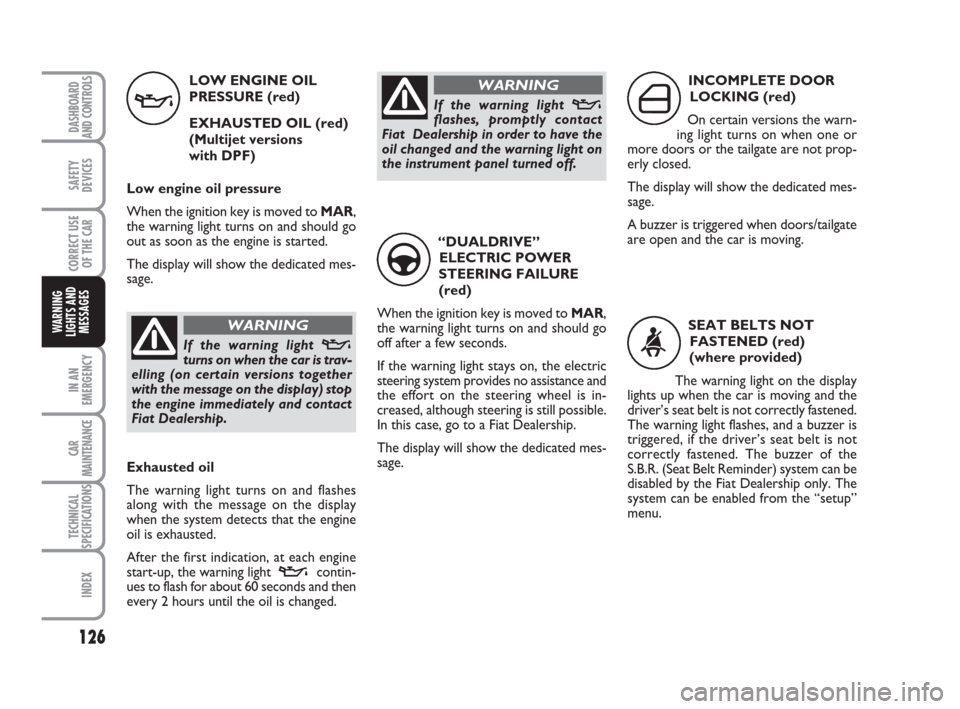
LOW ENGINE OIL
PRESSURE (red)
EXHAUSTED OIL (red)
(Multijet versions
with DPF)
Low engine oil pressure
When the ignition key is moved to MAR,
the warning light turns on and should go
out as soon as the engine is started.
The display will show the dedicated mes-
sage.
v
Exhausted oil
The warning light turns on and flashes
along with the message on the display
when the system detects that the engine
oil is exhausted.
After the first indication, at each engine
start-up, the warning light
vcontin-
ues to flash for about 60 seconds and then
every 2 hours until the oil is changed.“DUALDRIVE”
ELECTRIC POWER
STEERING FAILURE
(red)
When the ignition key is moved to MAR,
the warning light turns on and should go
off after a few seconds.
If the warning light stays on, the electric
steering system provides no assistance and
the effort on the steering wheel is in-
creased, although steering is still possible.
In this case, go to a Fiat Dealership.
The display will show the dedicated mes-
sage.
g
INCOMPLETE DOOR
LOCKING (red)
On certain versions the warn-
ing light turns on when one or
more doors or the tailgate are not prop-
erly closed.
The display will show the dedicated mes-
sage.
A buzzer is triggered when doors/tailgate
are open and the car is moving.
´
SEAT BELTS NOT
FASTENED (red)
(where provided)
The warning light on the display
lights up when the car is moving and the
driver’s seat belt is not correctly fastened.
The warning light flashes, and a buzzer is
triggered, if the driver’s seat belt is not
correctly fastened. The buzzer of the
S.B.R. (Seat Belt Reminder) system can be
disabled by the Fiat Dealership only. The
system can be enabled from the “setup”
menu.
with the message on the display) stop
the engine immediately and contact
Fiat Dealership.
WARNING
If the warning light vflashes, promptly contact
Fiat Dealership in order to have the
oil changed and the warning light on
the instrument panel turned off.
WARNING
123-132 idea GB 1 ed 10-07-2008 8:29 Pagina 126
Page 133 of 210
132
IN AN
EMERGENCY
CAR
MAINTENANCE
TECHNICAL
SPECIFICATIONS
INDEX
DASHBOARD
AND CONTROLS
SAFETY
DEVICES
CORRECT USE
OF THE CAR
WARNING
LIGHTS AND
MESSAGES
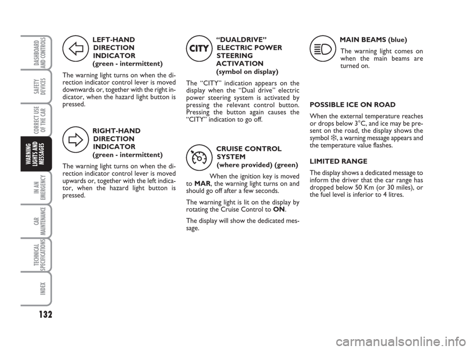
LEFT-HAND
DIRECTION
INDICATOR
(green - intermittent)
The warning light turns on when the di-
rection indicator control lever is moved
downwards or, together with the right in-
dicator, when the hazard light button is
pressed.
F
RIGHT-HAND
DIRECTION
INDICATOR
(green - intermittent)
The warning light turns on when the di-
rection indicator control lever is moved
upwards or, together with the left indica-
tor, when the hazard light button is
pressed.
D
“DUALDRIVE”
ELECTRIC POWER
STEERING
ACTIVATION
(symbol on display)
The “CITY” indication appears on the
display when the “Dual drive” electric
power steering system is activated by
pressing the relevant control button.
Pressing the button again causes the
“CITY” indication to go off.
CITY
CRUISE CONTROL
SYSTEM
(where provided) (green)
When the ignition key is moved
to MAR, the warning light turns on and
should go off after a few seconds.
The warning light is lit on the display by
rotating the Cruise Control to ON.
The display will show the dedicated mes-
sage.
Ü
MAIN BEAMS (blue)
The warning light comes on
when the main beams are
turned on.
1
POSSIBLE ICE ON ROAD
When the external temperature reaches
or drops below 3°C, and ice may be pre-
sent on the road, the display shows the
symbol
❄, a warning message appears and
the temperature value flashes.
LIMITED RANGE
The display shows a dedicated message to
inform the driver that the car range has
dropped below 50 Km (or 30 miles), or
the fuel level is inferior to 4 litres.
123-132 idea GB 1 ed 10-07-2008 8:29 Pagina 132
Page 136 of 210
135
CAR
MAINTENANCE
TECHNICAL
SPECIFICATIONS
INDEX
DASHBOARD
AND CONTROLS
SAFETY
DEVICES
CORRECT USE
OF THE CAR
WARNING
LIGHTS AND
MESSAGES
IN AN
EMERGENCY
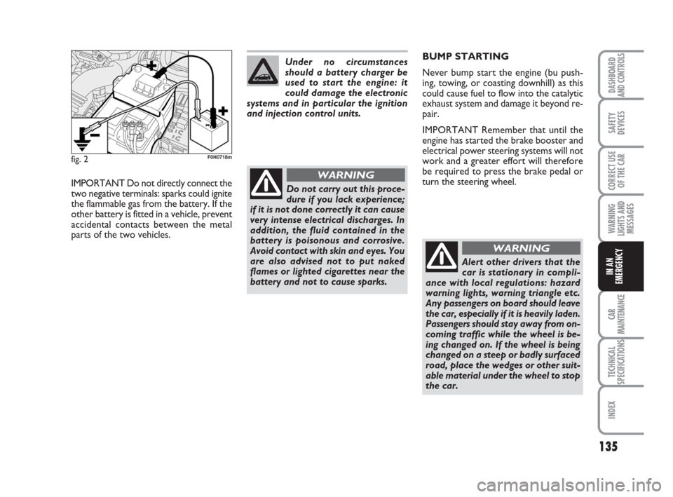
fig. 2F0H0718m
IMPORTANT Do not directly connect the
two negative terminals: sparks could ignite
the flammable gas from the battery. If the
other battery is fitted in a vehicle, prevent
accidental contacts between the metal
parts of the two vehicles.Do not carry out this proce-
dure if you lack experience;
if it is not done correctly it can cause
very intense electrical discharges. In
addition, the fluid contained in the
battery is poisonous and corrosive.
Avoid contact with skin and eyes. You
are also advised not to put naked
flames or lighted cigarettes near the
battery and not to cause sparks.
WARNING
Under no circumstances
should a battery charger be
used to start the engine: it
could damage the electronic
systems and in particular the ignition
and injection control units.BUMP STARTING
Never bump start the engine (bu push-
ing, towing, or coasting downhill) as this
could cause fuel to flow into the catalytic
exhaust system and damage it beyond re-
pair.
IMPORTANT Remember that until the
engine has started the brake booster and
electrical power steering systems will not
work and a greater effort will therefore
be required to press the brake pedal or
turn the steering wheel.
Alert other drivers that the
car is stationary in compli-
ance with local regulations: hazard
warning lights, warning triangle etc.
Any passengers on board should leave
the car, especially if it is heavily laden.
Passengers should stay away from on-
coming traffic while the wheel is be-
ing changed on. If the wheel is being
changed on a steep or badly surfaced
road, place the wedges or other suit-
able material under the wheel to stop
the car.
WARNING
133-160 idea GB 1 ed 10-07-2008 8:30 Pagina 135
Page 158 of 210
157
CAR
MAINTENANCE
TECHNICAL
SPECIFICATIONS
INDEX
DASHBOARD
AND CONTROLS
SAFETY
DEVICES
CORRECT USE
OF THE CAR
WARNING
LIGHTS AND
MESSAGES
IN AN
EMERGENCY
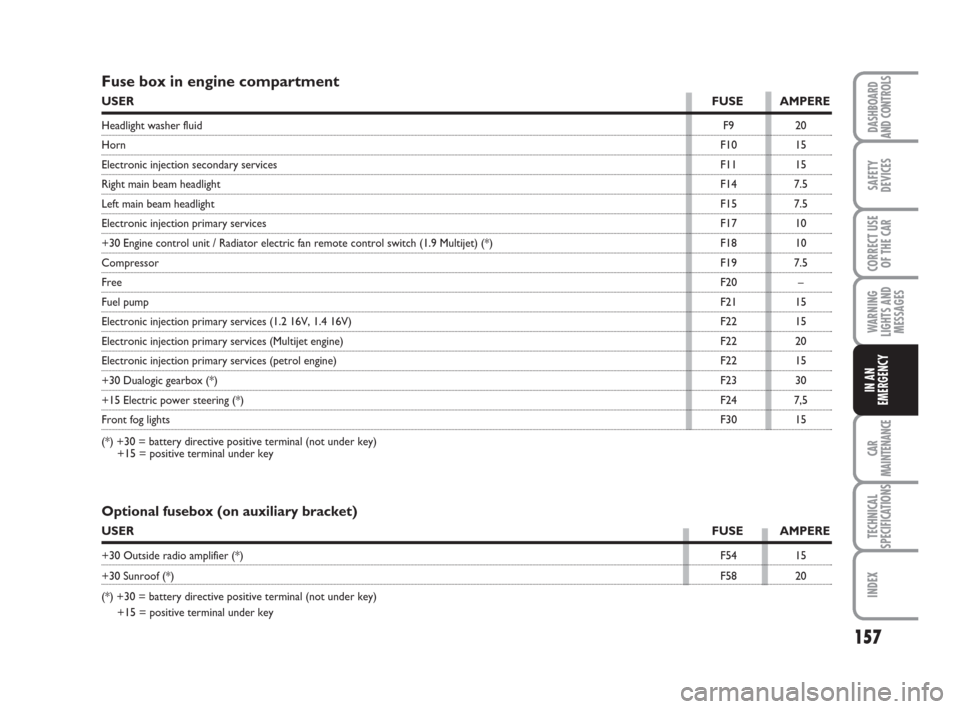
Fuse box in engine compartment
USERFUSE AMPERE
Headlight washer fluidF9 20
HornF10 15
Electronic injection secondary servicesF11 15
Right main beam headlightF14 7.5
Left main beam headlightF15 7.5
Electronic injection primary servicesF17 10
+30 Engine control unit / Radiator electric fan remote control switch (1.9 Multijet) (*) F18 10
CompressorF19 7.5
FreeF20 –
Fuel pumpF21 15
Electronic injection primary services (1.2 16V, 1.4 16V)F22 15
Electronic injection primary services (Multijet engine)F22 20
Electronic injection primary services (petrol engine)F22 15
+30 Dualogic gearbox (*)F23 30
+15 Electric power steering (*)F24 7,5
Front fog lightsF30 15
(*) +30 = battery directive positive terminal (not under key)
+15 = positive terminal under key
Optional fusebox (on auxiliary bracket)
USERFUSE AMPERE
+30 Outside radio amplifier (*)F54 15
+30 Sunroof (*)F58 20
(*) +30 = battery directive positive terminal (not under key)
+15 = positive terminal under key
133-160 idea GB 1 ed 10-07-2008 8:30 Pagina 157