ECU FIAT IDEA 2009 1.G User Guide
[x] Cancel search | Manufacturer: FIAT, Model Year: 2009, Model line: IDEA, Model: FIAT IDEA 2009 1.GPages: 210, PDF Size: 3.62 MB
Page 151 of 210

150
STARTING
AND DRIVING
MAINTENANCE
AND CARE
TECHNICAL
SPECIFICATIONS
ALPHABETICAL
INDEX
DASHBOARD
AND
CONTROLS
SAFETY
WARNING
LIGHTS AND
MESSAGES
IN AN
EMERGENCY
fig. 27F0H0187mfig. 28F0H0188m
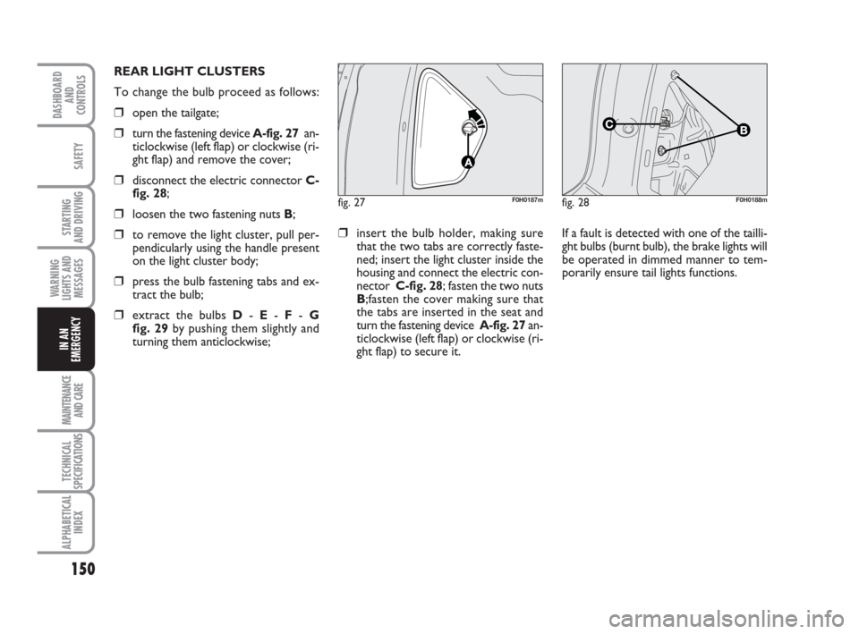
REAR LIGHT CLUSTERS
To change the bulb proceed as follows:
❒open the tailgate;
❒turn the fastening device A-fig. 27an-
ticlockwise (left flap) or clockwise (ri-
ght flap) and remove the cover;
❒disconnect the electric connector C-
fig. 28;
❒loosen the two fastening nuts B;
❒to remove the light cluster, pull per-
pendicularly using the handle present
on the light cluster body;
❒press the bulb fastening tabs and ex-
tract the bulb;
❒extract the bulbs D- E- F- G
fig. 29by pushing them slightly and
turning them anticlockwise;
❒insert the bulb holder, making sure
that the two tabs are correctly faste-
ned; insert the light cluster inside the
housing and connect the electric con-
nector C-fig. 28; fasten the two nuts
B;fasten the cover making sure that
the tabs are inserted in the seat and
turn the fastening device A-fig. 27an-
ticlockwise (left flap) or clockwise (ri-
ght flap) to secure it. If a fault is detected with one of the tailli-
ght bulbs (burnt bulb), the brake lights will
be operated in dimmed manner to tem-
porarily ensure tail lights functions.
Page 153 of 210

152
STARTING
AND DRIVING
MAINTENANCE
AND CARE
TECHNICAL
SPECIFICATIONS
ALPHABETICAL
INDEX
DASHBOARD
AND
CONTROLS
SAFETY
WARNING
LIGHTS AND
MESSAGES
IN AN
EMERGENCY
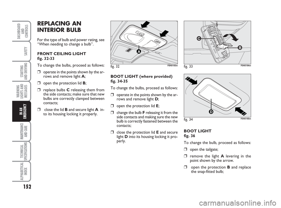
REPLACING AN
INTERIOR BULB
For the type of bulb and power rating, see
“When needing to change a bulb”.
FRONT CEILING LIGHT
fig. 32-33
To change the bulbs, proceed as follows:
❒operate in the points shown by the ar-
rows and remove light A;
❒open the protection lid B;
❒replace bulbs Creleasing them from
the side contacts; make sure that new
bulbs are correctly clamped between
contacts;
❒close the lid Band secure light Ain-
to its housing locking it properly. BOOT LIGHT (where provided)
fig. 34-35
To change the bulbs, proceed as follows:
❒operate in the points shown by the ar-
rows and remove light D;
❒open the protection lid E;
❒change the bulb F releasing it from the
side contacts and making sure the new
bulb is correctly fastened between the
contacts;
❒close the protection lid Eand secure
light Dinto its housing locking it pro-
perly.
fig. 32F0H0193mfig. 33F0H0194m
fig. 34F0H0195m
BOOT LIGHT
fig. 36
To change the bulb, proceed as follows:
❒open the tailgate;
❒remove the light Alevering in the
point shown by the arrow.
❒open the protection Band replace
the snap-fitted bulb;
Page 157 of 210

156
STARTING
AND DRIVING
MAINTENANCE
AND CARE
TECHNICAL
SPECIFICATIONS
ALPHABETICAL
INDEX
DASHBOARD
AND
CONTROLS
SAFETY
WARNING
LIGHTS AND
MESSAGES
IN AN
EMERGENCY
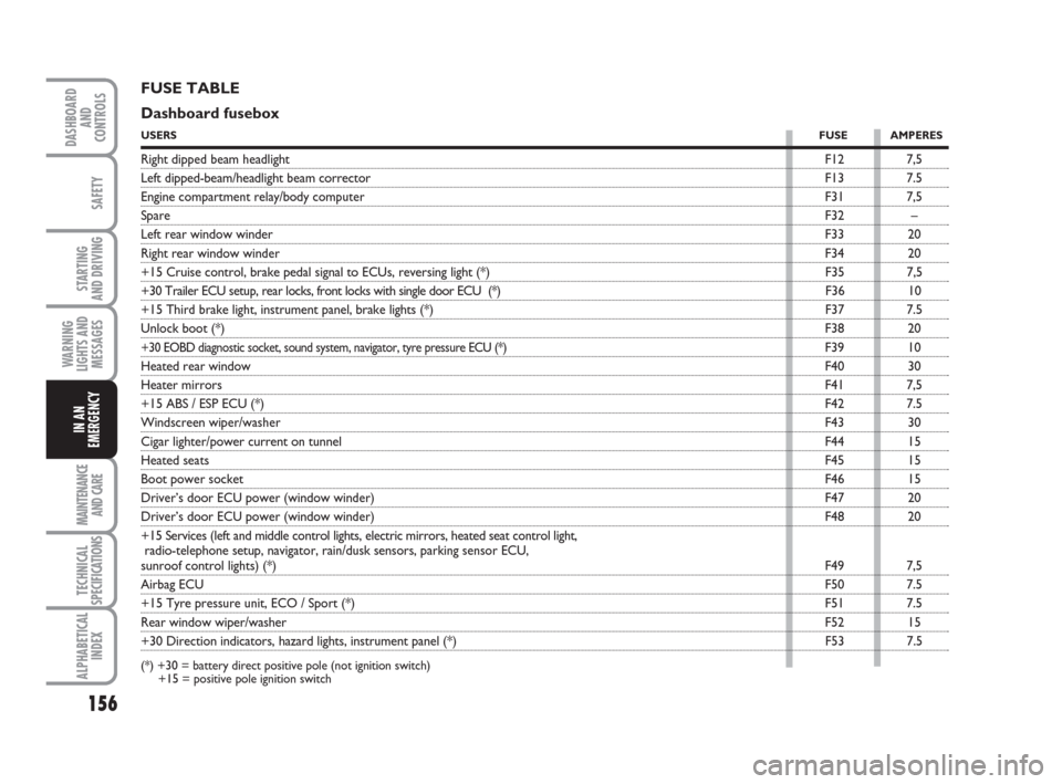
FUSE TABLE
Dashboard fusebox
USERSFUSE AMPERES
Right dipped beam headlightF12 7,5
Left dipped-beam/headlight beam correctorF13 7.5
Engine compartment relay/body computerF31 7,5
SpareF32 –
Left rear window winderF33 20
Right rear window winderF34 20
+15 Cruise control, brake pedal signal to ECUs, reversing light (*) F35 7,5
+30 Trailer ECU setup, rear locks, front locks with single door ECU (*) F36 10
+15 Third brake light, instrument panel, brake lights (*) F37 7.5
Unlock boot (*)F38 20
+30 EOBD diagnostic socket, sound system, navigator, tyre pressure ECU (*)F39 10
Heated rear windowF40 30
Heater mirrorsF41 7,5
+15 ABS / ESP ECU (*)F42 7.5
Windscreen wiper/washerF43 30
Cigar lighter/power current on tunnelF44 15
Heated seatsF45 15
Boot power socketF46 15
Driver’s door ECU power (window winder)F47 20
Driver’s door ECU power (window winder)F48 20
+15 Services (left and middle control lights, electric mirrors, heated seat control light,
radio-telephone setup, navigator, rain/dusk sensors, parking sensor ECU,
sunroof control lights) (*)F49 7,5
Airbag ECUF50 7.5
+15 Tyre pressure unit, ECO / Sport (*)F51 7.5
Rear window wiper/washerF52 15
+30 Direction indicators, hazard lights, instrument panel (*) F53 7.5
(*) +30 = battery direct positive pole (not ignition switch)
+15 = positive pole ignition switch
Page 158 of 210

157
STARTING
AND DRIVING
MAINTENANCE
AND CARE
TECHNICAL
SPECIFICATIONS
ALPHABETICAL
INDEX
DASHBOARD
AND
CONTROLS
SAFETY
WARNING
LIGHTS AND
MESSAGES
IN AN
EMERGENCY
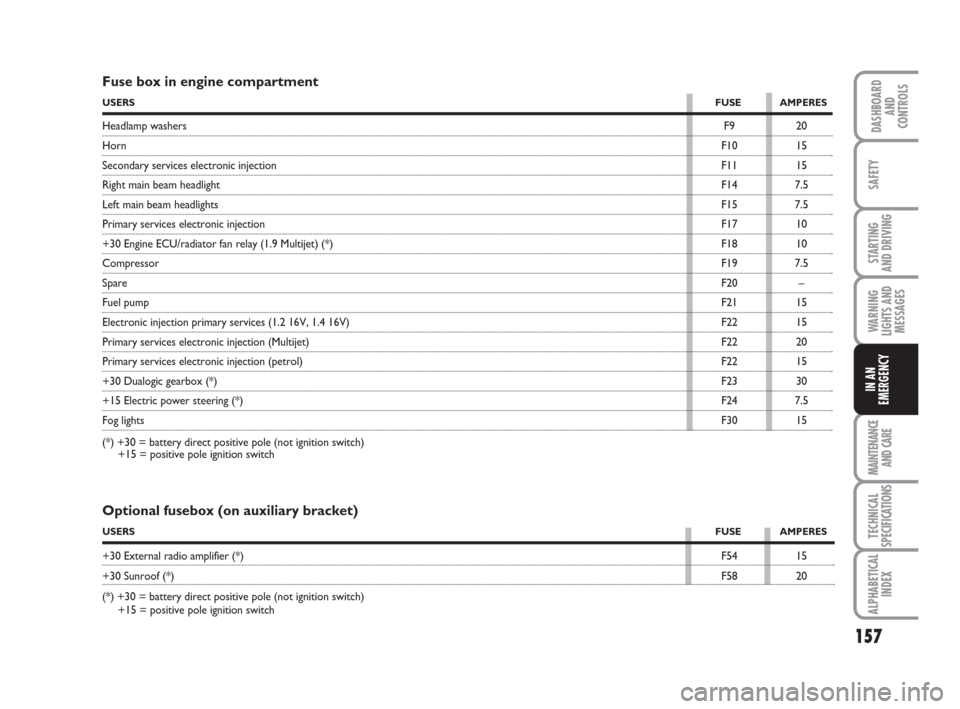
Fuse box in engine compartment
USERSFUSE AMPERES
Headlamp washersF9 20
HornF10 15
Secondary services electronic injectionF11 15
Right main beam headlightF14 7.5
Left main beam headlightsF15 7.5
Primary services electronic injectionF17 10
+30 Engine ECU/radiator fan relay (1.9 Multijet) (*)F18 10
CompressorF19 7.5
SpareF20 –
Fuel pumpF21 15
Electronic injection primary services (1.2 16V, 1.4 16V)F22 15
Primary services electronic injection (Multijet)F22 20
Primary services electronic injection (petrol)F22 15
+30 Dualogic gearbox (*)F23 30
+15 Electric power steering (*)F24 7.5
Fog lightsF30 15
(*) +30 = battery direct positive pole (not ignition switch)
+15 = positive pole ignition switch
Optional fusebox (on auxiliary bracket)
USERSFUSE AMPERES
+30 External radio amplifier (*)F54 15
+30 Sunroof (*)F58 20
(*) +30 = battery direct positive pole (not ignition switch)
+15 = positive pole ignition switch