boot FIAT IDEA 2009 1.G User Guide
[x] Cancel search | Manufacturer: FIAT, Model Year: 2009, Model line: IDEA, Model: FIAT IDEA 2009 1.GPages: 210, PDF Size: 3.62 MB
Page 82 of 210
81
SAFETY
STARTING
AND DRIVING
WARNING
LIGHTS AND
MESSAGES
IN AN
EMERGENCY
MAINTENANCE
AND CARE
TECHNICAL
SPECIFICATIONS
ALPHABETICAL
INDEX
DASHBOARD
AND CONTROLS
The bonnet may drop sud-
denly if the supporting rod is
not in correct position.
WARNING
Perform these operations
when the car is stationary
only.
WARNING
IMPORTANT Always check that the bon-
net is closed properly to avoid its opening
while the vehicle is travelling.ROOF BARS
(where provided)
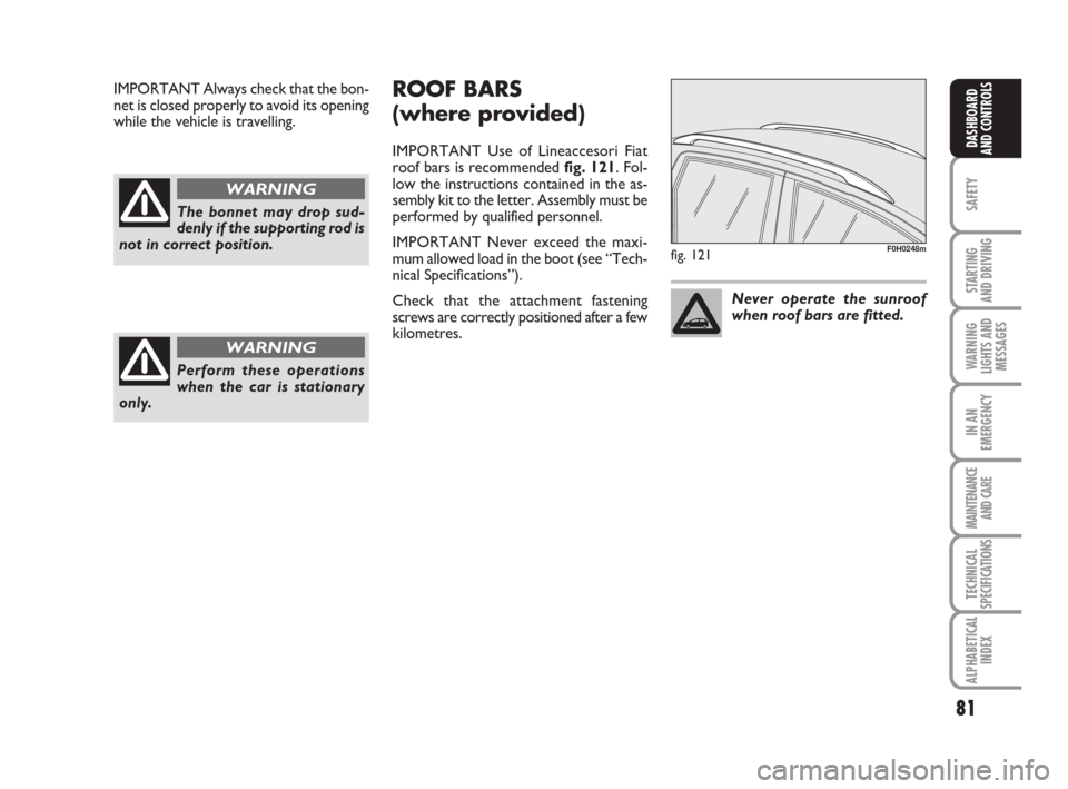
IMPORTANT Use of Lineaccesori Fiat
roof bars is recommended fig. 121. Fol-
low the instructions contained in the as-
sembly kit to the letter. Assembly must be
performed by qualified personnel.
IMPORTANT Never exceed the maxi-
mum allowed load in the boot (see “Tech-
nical Specifications”).
Check that the attachment fastening
screws are correctly positioned after a few
kilometres.
fig. 121F0H0248m
Never operate the sunroof
when roof bars are fitted.
Page 83 of 210
82
SAFETY
STARTING
AND DRIVING
WARNING
LIGHTS AND
MESSAGES
IN AN
EMERGENCY
MAINTENANCE
AND CARE
TECHNICAL
SPECIFICATIONS
ALPHABETICAL
INDEX
DASHBOARD
AND CONTROLS
HEADLIGHTS
BEAM DIRECTION
Correct direction of the headlights is es-
sential for the comfort and safety of the
driver and the other road users. The head-
lights must be correctly directed to ensure
the best visibility conditions when the
headlights are on. Contact a Fiat Dealer-
ship to have the headlights properly ad-
justed.
HEADLIGHT CORRECTOR
This device works with the key at MAR
and the dipped beam headlights on. The
car will slant backwards when it is loaded,
raising the light beam. The beams must
therefore be directed again in this case.
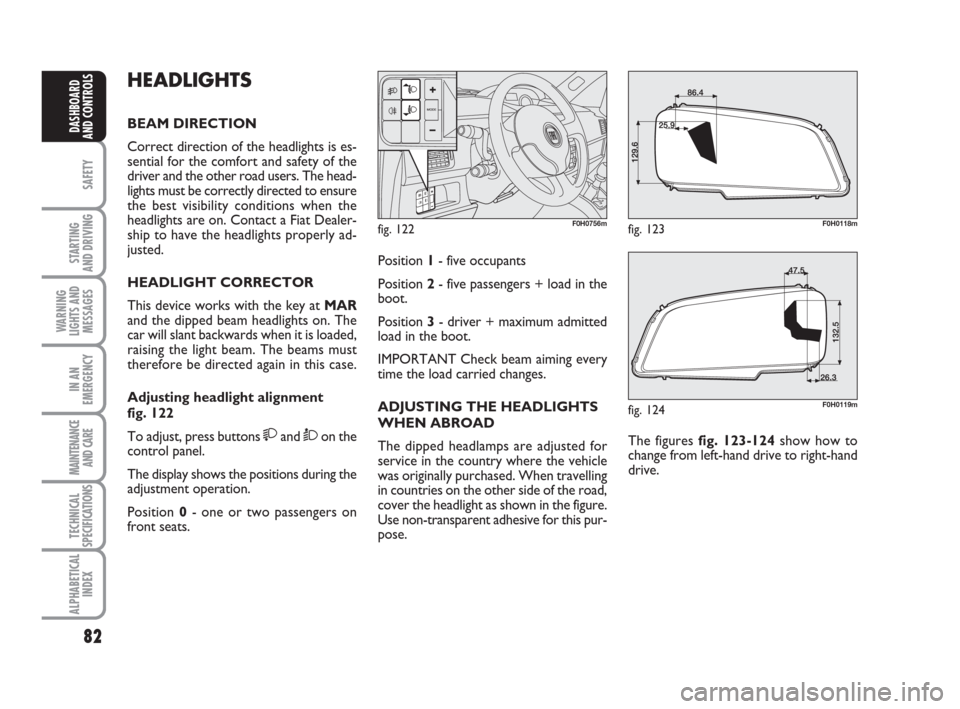
Adjusting headlight alignment
fig. 122
To adjust, press buttons
and Òon the
control panel.
The display shows the positions during the
adjustment operation.
Position 0- one or two passengers on
front seats.
fig. 122F0H0756m
Position 1- five occupants
Position 2- five passengers + load in the
boot.
Position 3- driver + maximum admitted
load in the boot.
IMPORTANT Check beam aiming every
time the load carried changes.
ADJUSTING THE HEADLIGHTS
WHEN ABROAD
The dipped headlamps are adjusted for
service in the country where the vehicle
was originally purchased. When travelling
in countries on the other side of the road,
cover the headlight as shown in the figure.
Use non-transparent adhesive for this pur-
pose.The figures fig. 123-124 show how to
change from left-hand drive to right-hand
drive.
fig. 123F0H0118m
fig. 124F0H0119m
Page 97 of 210
96
STARTING
AND DRIVING
WARNING
LIGHTS AND
MESSAGES
IN AN
EMERGENCY
MAINTENANCE
AND CARE
TECHNICAL
SPECIFICATIONS
ALPHABETICAL
INDEX
DASHBOARD
AND
CONTROLS
SAFETY
fig. 5F0H0311m
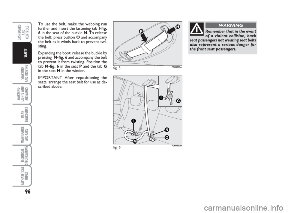
To use the belt, make the webbing run
further and insert the fastening tab I-fig.
6in the seat of the buckle N. To release
the belt: press button Oand accompany
the belt as it winds back to prevent twi-
sting.
Expanding the boot: release the buckle by
pressing M-fig. 6and accompany the belt
to prevent it from twisting. Position the
tab M-fig. 6in the seat Pand the tab G
in the seat Hin the winder.
IMPORTANT After repositioning the
seats, arrange the seat belt for use as de-
scribed above.
fig. 6F0H0310m
Remember that in the event
of a violent collision, back
seat passengers not wearing seat belts
also represent a serious danger for
the front seat passengers.
WARNING
Page 105 of 210
104
STARTING
AND DRIVING
WARNING
LIGHTS AND
MESSAGES
IN AN
EMERGENCY
MAINTENANCE
AND CARE
TECHNICAL
SPECIFICATIONS
ALPHABETICAL
INDEX
DASHBOARD
AND
CONTROLS
SAFETY
fig. 15F0H0140m
Fit the child seat when the
car is stationary. The child
seat is correctly anchored to the
brackets when you hear the click. Fol-
low the instructions for assembly, di-
sassembly and positioning that the
manufacturer must supply with the
child seat.
WARNING
fig. 14F0H0019m
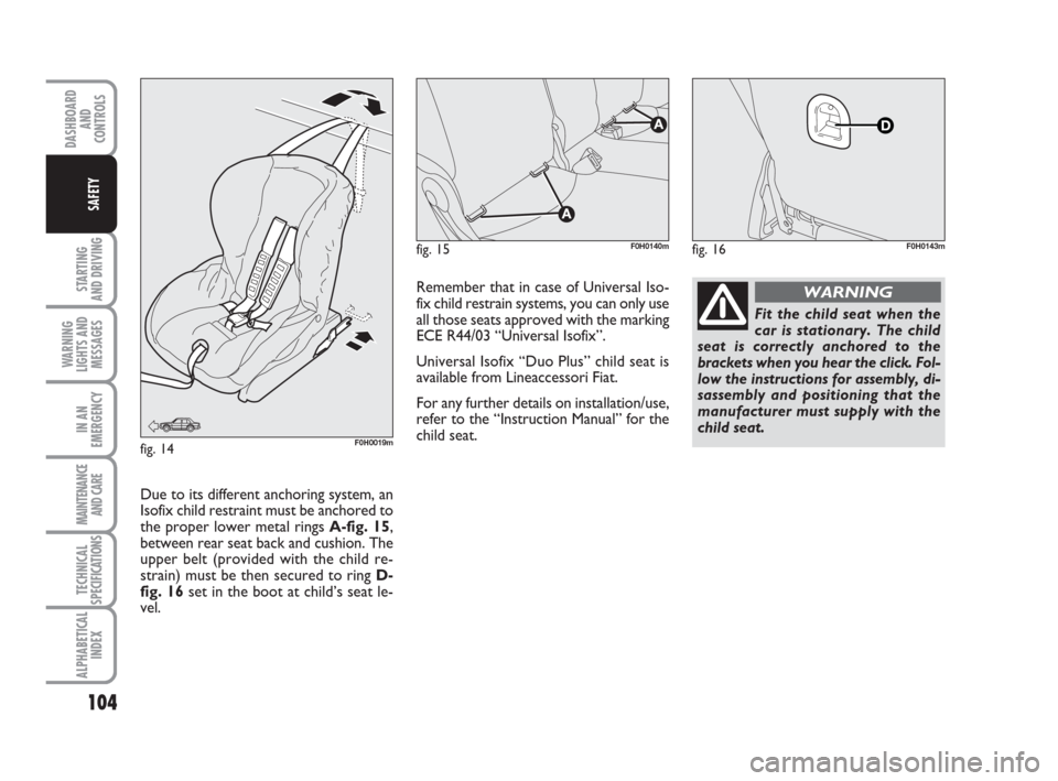
Due to its different anchoring system, an
Isofix child restraint must be anchored to
the proper lower metal rings A-fig. 15,
between rear seat back and cushion. The
upper belt (provided with the child re-
strain) must be then secured to ring D-
fig. 16set in the boot at child’s seat le-
vel.
fig. 16F0H0143m
Remember that in case of Universal Iso-
fix child restrain systems, you can only use
all those seats approved with the marking
ECE R44/03 “Universal Isofix”.
Universal Isofix “Duo Plus” child seat is
available from Lineaccessori Fiat.
For any further details on installation/use,
refer to the “Instruction Manual” for the
child seat.
Page 117 of 210
116
WARNING
LIGHTS AND
MESSAGES
IN AN
EMERGENCY
MAINTENANCE
AND CARE
TECHNICAL
SPECIFICATIONS
ALPHABETICAL
INDEX
DASHBOARD
AND
CONTROLS
SAFETY
STARTING
AND DRIVING
CONTAINING
RUNNING COSTS
Here are some suggestions which may
help you to keep the running costs of your
vehicle down and lower the amount of
toxic emissions released into the atmo-
sphere.
GENERAL CONSIDERATIONS
Car maintenance
Have checks and adjustments carried out
in accordance with the “Service schedu-
le”.
Tyres
Check tyre pressure regularly, at least on-
ce every four weeks: excessively low pres-
sure will increase fuel consumption be-
cause rolling resistance will be higher.
Unnecessary loads
Do not travel with an overloaded boot.
Do not travel with too much luggage
stowed in the boot. The weight of the car
(especially when driving in town) and its
trim greatly affects consumption and sta-
bility.Roof rack/ski rack
Remove the roof rack or the ski rack from
the roof after use. These accessories de-
crease aerodynamic penetration of the car
and have a negative effect on consumption.
It is better to use a trailer to transport
particularly bulky objects.
Electrical devices
Use electrical devices only for the amount
of time needed. Rear heated window, ad-
ditional headlights, windscreen wipers and
heater fan need a considerable amount of
energy, therefore increasing the require-
ment of current increases fuel consump-
tion (up to +25% in the urban cycle).
Climate control
The climate control system requires hi-
gher fuel consumption (up to +20% in ave-
rage): use the air vents when the exter-
nal temperature allows to.
Spoilers
The use of non-certified aerodynamic
items may adversely affect air drag and fuel
consumption levels.DRIVING STYLE
Starting
Do not warm the engine up with the car
standing: the engine warms up very slowly
in these conditions, increasing fuel con-
sumption and emissions. It is advisable to
start off immediately and slowly keeping
the engine speed down: the engine will
warm up much faster this way.
Unnecessary actions
Avoid revving up when starting at traffic
lights or before stopping the engine. The
latter action, like doubling the clutch, is un-
necessary and causes increase of con-
sumption and pollution.
Gear selection
Use a higher gear as soon as traffic and
road conditions allow. Using a low gear
for faster acceleration will increase fuel
consumption.
In the same way improper use of a high
gear increases consumption, emissions an
engine wear.
Page 137 of 210
136
STARTING
AND DRIVING
MAINTENANCE
AND CARE
TECHNICAL
SPECIFICATIONS
ALPHABETICAL
INDEX
DASHBOARD
AND
CONTROLS
SAFETY
WARNING
LIGHTS AND
MESSAGES
IN AN
EMERGENCY
FIX & GO AUTOMATIC
(QUICK TYRE REPAIR
KIT) (where provided)
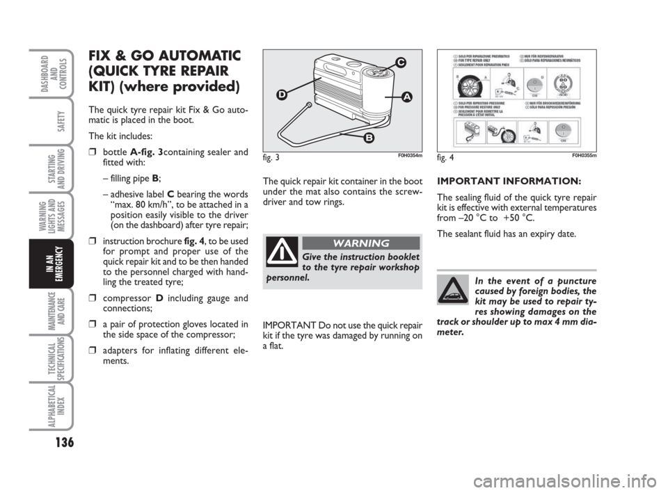
The quick tyre repair kit Fix & Go auto-
matic is placed in the boot.
The kit includes:
❒bottle A-fig. 3containing sealer and
fitted with:
– filling pipe B;
– adhesive label Cbearing the words
“max. 80 km/h”, to be attached in a
position easily visible to the driver
(on the dashboard) after tyre repair;
❒instruction brochure fig. 4, to be used
for prompt and proper use of the
quick repair kit and to be then handed
to the personnel charged with hand-
ling the treated tyre;
❒compressor Dincluding gauge and
connections;
❒a pair of protection gloves located in
the side space of the compressor;
❒adapters for inflating different ele-
ments.The quick repair kit container in the boot
under the mat also contains the screw-
driver and tow rings.
fig. 3F0H0354mfig. 4F0H0355m
Give the instruction booklet
to the tyre repair workshop
personnel.
WARNING
IMPORTANT Do not use the quick repair
kit if the tyre was damaged by running on
a flat.IMPORTANT INFORMATION:
The sealing fluid of the quick tyre repair
kit is effective with external temperatures
from –20 °C to +50 °C.
The sealant fluid has an expiry date.
In the event of a puncture
caused by foreign bodies, the
kit may be used to repair ty-
res showing damages on the
track or shoulder up to max 4 mm dia-
meter.
Page 142 of 210
141
STARTING
AND DRIVING
MAINTENANCE
AND CARE
TECHNICAL
SPECIFICATIONS
ALPHABETICAL
INDEX
DASHBOARD
AND
CONTROLS
SAFETY
WARNING
LIGHTS AND
MESSAGES
IN AN
EMERGENCY
The jack may only be used to
replace wheels on the car
which it equips or other cars of the
same model. Never use the jack for
other purposes, such as lifting other
models of vehicle. Never use the jack
to carry out repairs under the car. In-
correct positioning of the jack may
cause the car to fall. Do not use the
jack for loads higher than those
shown on the label. Snow chains can-
not be fitted on a space saver spare
wheel. Therefore, if a front wheel
(drive wheel) is punctured and you
need to use snow chains, swap with a
rear wheel. In this way, you will ha-
ve two normal wheels on the front on
which you can fit snow chains and
solve the emergency.
WARNING
Incorrect wheel cup assem-
bly may cause it to come off
when the car is travelling. Never tam-
per with the inflation valve. Never in-
troduce tools of any kind between the
rim and the tyre. Check tyre and spa-
ce saver spare wheel pressure regu-
larly referring to the values shown in
the “Technical Specifications” chap-
ter.
WARNINGImportant notes:
❒the jack cannot be repaired: replace
with an original spare part if damaged;
❒no tool other than its cranking devi-
ce may be fitted on the jack.
To change a wheel proceed as follows:
❒stop the car in a position so that it is
not a danger for on-coming traffic and
where you can replace the wheel sa-
fely. The ground must be flat and com-
pact;
❒Turn the engine off and pull up the
handbrake.
❒Engage first gear or reverse;
❒lift the boot mat;
❒loosen the fastening device A-fig. 11;
❒take out the tool container Band take
it near to the wheel to be changed;
❒take the space saver spare wheel C;
Page 145 of 210
144
STARTING
AND DRIVING
MAINTENANCE
AND CARE
TECHNICAL
SPECIFICATIONS
ALPHABETICAL
INDEX
DASHBOARD
AND
CONTROLS
SAFETY
WARNING
LIGHTS AND
MESSAGES
IN AN
EMERGENCY
WHEN NEEDING TO
CHANGE A BULB
GENERAL INSTRUCTIONS
❒When a bulb is not working, check
that the corresponding fuse is intact
before replacing it: refer to the “If a fu-
se blows” paragraph in this chapter for
fuse location.
❒before changing a bulb check the con-
tacts for oxidation;
❒Burnt bulbs must be replaced by
others of the same type and power.
❒Always check the height of the head-
light beam after changing a bulb. Versions with alloy rims
❒Check that the hub contact surfaces
are clean;
❒fit the normal wheel centring it on the
pins, lead in the fastening screws and
tighten them using the wrench provi-
ded;
❒lower the car and remove the jack;
❒using the wrench provided, fully tigh-
ten the bolts in the sequence shown
in fig. 16.
❒snap fit the wheel cup on the hub.
When you have finished
❒stow the spare wheel C-fig. 11 in the
space provided in the boot;
❒Fit the jack partially open in its box B-
fig. 11forcing it lightly to prevent it
from vibrating when travelling;
❒put the tools back into their places in
the container;
❒arrange the container and tools in the
spare wheel and secure the fastening
device A-fig. 11;
❒rearrange the preformed boot cover
correctly.
Modifications or repairs to
the electrical system (elec-
tronic control units) that are not car-
ried out properly or do not take the
technical specifications of the system
into account can cause malfunctions
leading to the risk of fire.
WARNING
Halogen bulbs contain pres-
surised gas which may cau-
se small fragments of glass to be
projected outwards if the bulb is
broken.
WARNING
Halogen lamps must be hand-
led holding the metallic part
only. Touching the transpa-
rent part of the bulb with
your fingers may reduce the intensity
of the emitted light and even compro-
mise duration of the lamp itself. In the
case of accidental contact, rub the
lamp with a cloth and spirit and leave
to dry.IMPORTANT A slight misting may appear
on the internal surface of the headlight:
this does not indicate a fault and is cau-
sed by low temperature and the degree of
humidity in the air. Misting will rapidly di-
sappear when the headlights are switched
on. The presence of drops inside the head-
lights indicates infiltration of water. Go to
a Fiat Dealership.
Page 147 of 210
146
STARTING
AND DRIVING
MAINTENANCE
AND CARE
TECHNICAL
SPECIFICATIONS
ALPHABETICAL
INDEX
DASHBOARD
AND
CONTROLS
SAFETY
WARNING
LIGHTS AND
MESSAGES
IN AN
EMERGENCY
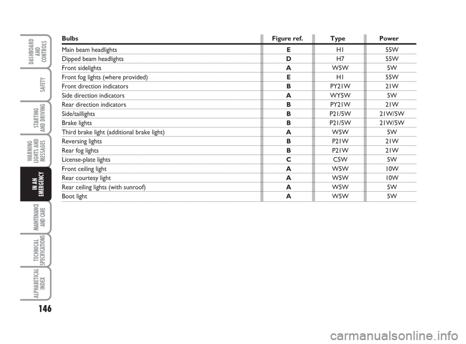
Bulbs Figure ref. Type Power
Main beam headlightsEH1 55W
Dipped beam headlights DH7 55W
Front sidelights AW5W 5W
Front fog lights (where provided)EH1 55W
Front direction indicators BPY21W 21W
Side direction indicators AWY5W 5W
Rear direction indicators BPY21W 21W
Side/taillights BP21/5W 21W/5W
Brake lights BP21/5W 21W/5W
Third brake light (additional brake light) AW5W 5W
Reversing lights BP21W 21W
Rear fog lights BP21W 21W
License-plate lights CC5W 5W
Front ceiling lightAW5W 10W
Rear courtesy lightAW5W 10W
Rear ceiling lights (with sunroof)AW5W 5W
Boot light AW5W 5W
Page 153 of 210
152
STARTING
AND DRIVING
MAINTENANCE
AND CARE
TECHNICAL
SPECIFICATIONS
ALPHABETICAL
INDEX
DASHBOARD
AND
CONTROLS
SAFETY
WARNING
LIGHTS AND
MESSAGES
IN AN
EMERGENCY
REPLACING AN
INTERIOR BULB
For the type of bulb and power rating, see
“When needing to change a bulb”.
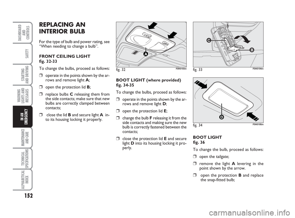
FRONT CEILING LIGHT
fig. 32-33
To change the bulbs, proceed as follows:
❒operate in the points shown by the ar-
rows and remove light A;
❒open the protection lid B;
❒replace bulbs Creleasing them from
the side contacts; make sure that new
bulbs are correctly clamped between
contacts;
❒close the lid Band secure light Ain-
to its housing locking it properly. BOOT LIGHT (where provided)
fig. 34-35
To change the bulbs, proceed as follows:
❒operate in the points shown by the ar-
rows and remove light D;
❒open the protection lid E;
❒change the bulb F releasing it from the
side contacts and making sure the new
bulb is correctly fastened between the
contacts;
❒close the protection lid Eand secure
light Dinto its housing locking it pro-
perly.
fig. 32F0H0193mfig. 33F0H0194m
fig. 34F0H0195m
BOOT LIGHT
fig. 36
To change the bulb, proceed as follows:
❒open the tailgate;
❒remove the light Alevering in the
point shown by the arrow.
❒open the protection Band replace
the snap-fitted bulb;