clock FIAT IDEA 2009 1.G User Guide
[x] Cancel search | Manufacturer: FIAT, Model Year: 2009, Model line: IDEA, Model: FIAT IDEA 2009 1.GPages: 210, PDF Size: 3.62 MB
Page 54 of 210
53
SAFETY
STARTING
AND DRIVING
WARNING
LIGHTS AND
MESSAGES
IN AN
EMERGENCY
MAINTENANCE
AND CARE
TECHNICAL
SPECIFICATIONS
ALPHABETICAL
INDEX
DASHBOARD
AND CONTROLS
Manual intervention is only required for
the following functions during fully auto-
matic operation.
❒MONOto uniform the temperature
and the air distribution on front pas-
senger or rear passenger zones to the
driver’s zone;
❒…air recirculation, to keep it always
on or off;
❒-to speed up demisting/defrosting of
windscreen, side windows, rear window
and door mirrors;
❒(to demist/defrost the heated rear
window and the external rearview
mirrors.
During completely automatic system op-
eration, you can vary the set temperature,
the air distribution and the fan speed us-
ing the corresponding buttons or knobs
at any time: the system will automatically
change settings to adapt to the new re-
quest.
During fully automatic operation (FULL
AUTO), the word FULLwill dissapear
if the air distribution, air speed, compres-
sor and/or recirculation settings are
changed. In this way, the functions will
switch from automatic to manual control until AUTOis pressed again. The fan
speed is the same in all the zones of the
passenger compartment.
With on or more manually set functions,
the introduced air temperature is still
managed automatically by the system, ex-
cept for when the compressor is off: in the
case, the air introduced into the passen-
ger compartment cannot be cooler than
the outside air.
CONTROLS FOR
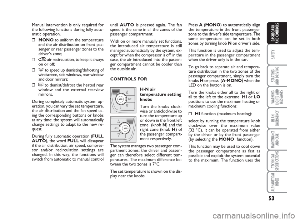
H-N air
temperature setting
knobs
Turn the knobs clock-
wise or anticlockwise to
turn the temperature up
or down in the front left
zone (knob N) and the
right zone (knob H) of
the passenger compart-
ment respectively.
The system manages two passenger com-
partment zones: the driver and passen-
ger can therefore select different tem-
peratures. The maximum difference be-
tween the two zones is 7°C.
The set temperature is shown on the dis-
play near the knobs.Press A(MONO) to automatically align
the temperature in the front passenger
zone to the driver’s side temperature. The
same temperature can be set in both
zones by turning knob N on driver’s side.
This function is used to adjust the tem-
perature in the passenger compartment
when the driver only is in the car.
To go back to separate air and tempera-
ture distribution in the two zones of the
passenger compartment, simply turn the
knobs H or press (A-MONO) when the
LED on the button is on.
Turn the knobs either all to the right or
all to the left to the extreme HIor LO
positions to use the maximum heating or
maximum cooling functions:
❒HIfunction (maximum heating):
select by turning the temperature knob
clockwise over the maximum value
(32 °C). It can be operated from either
by the driver or by the front passenger
(by selecting the MONOfunction).
This function may be used to cool down
the passenger compartment as fast as
possible and exploit the system potential
to the maximum. The function uses the
Page 55 of 210
54
SAFETY
STARTING
AND DRIVING
WARNING
LIGHTS AND
MESSAGES
IN AN
EMERGENCY
MAINTENANCE
AND CARE
TECHNICAL
SPECIFICATIONS
ALPHABETICAL
INDEX
DASHBOARD
AND CONTROLS
maximum coolant temperature while air
and fan speed distribution are managed
by the system according to conditions.
Specifically, if the heating fluid is not
warm enough, the fan will not start up at
the maximum speed immediately to limit
introducing excessively cool air into the
passenger compartment.
All manual settings will be allowed when
this function is on.
To switch the function off, simply turn
the temperature knob anticlockwise and
set the required temperature.
❒LOfunction (maximum cooling):
select by turning the temperature knob
anticlockwise beyond the minimum
value (16 °C). It can be operated from
either by the driver or by the front pas-
senger (by selecting the MONOfunc-
tion).
This function may be used to cool down
the passenger compartment as fast as
possible and exploit the system potential
to the maximum. The function activates
air recirculation and the climate control
compressor, air distribution and fan
speed are managed by the system
according to environmental conditions. All manual settings will be allowed when
this function is on.
To switch the function off, simply turn
the temperature knob clockwise and set
the required temperature.
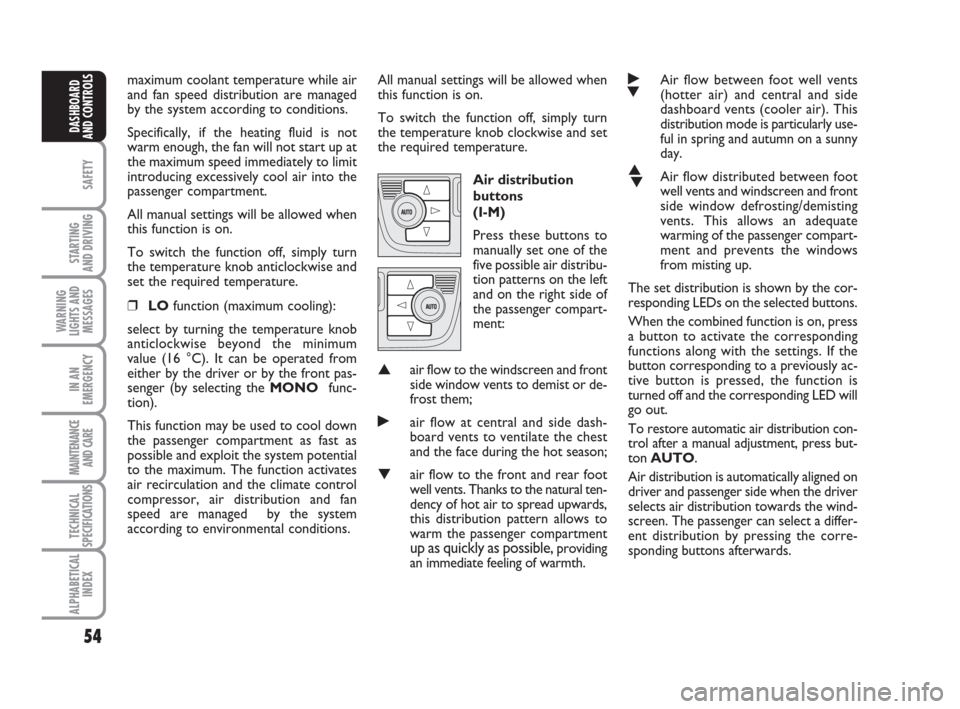
Air distribution
buttons
(I-M)
Press these buttons to
manually set one of the
five possible air distribu-
tion patterns on the left
and on the right side of
the passenger compart-
ment:
▲air flow to the windscreen and front
side window vents to demist or de-
frost them;
˙air flow at central and side dash-
board vents to ventilate the chest
and the face during the hot season;
▼air flow to the front and rear foot
well vents. Thanks to the natural ten-
dency of hot air to spread upwards,
this distribution pattern allows to
warm the passenger compartment
up as quickly as possible, providing
an immediate feeling of warmth.
˙
▼Air flow between foot well vents
(hotter air) and central and side
dashboard vents (cooler air). This
distribution mode is particularly use-
ful in spring and autumn on a sunny
day.
▲
▼Air flow distributed between foot
well vents and windscreen and front
side window defrosting/demisting
vents. This allows an adequate
warming of the passenger compart-
ment and prevents the windows
from misting up.
The set distribution is shown by the cor-
responding LEDs on the selected buttons.
When the combined function is on, press
a button to activate the corresponding
functions along with the settings. If the
button corresponding to a previously ac-
tive button is pressed, the function is
turned off and the corresponding LED will
go out.
To restore automatic air distribution con-
trol after a manual adjustment, press but-
ton AUTO.
Air distribution is automatically aligned on
driver and passenger side when the driver
selects air distribution towards the wind-
screen. The passenger can select a differ-
ent distribution by pressing the corre-
sponding buttons afterwards.
Page 74 of 210
73
SAFETY
STARTING
AND DRIVING
WARNING
LIGHTS AND
MESSAGES
IN AN
EMERGENCY
MAINTENANCE
AND CARE
TECHNICAL
SPECIFICATIONS
ALPHABETICAL
INDEX
DASHBOARD
AND CONTROLS
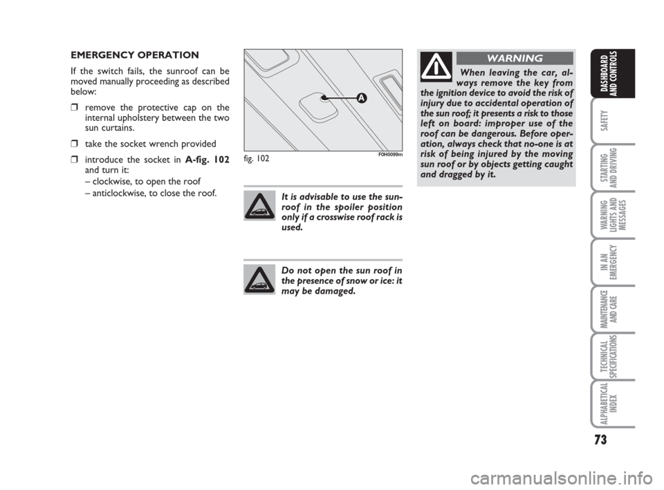
fig. 102F0H0099m
EMERGENCY OPERATION
If the switch fails, the sunroof can be
moved manually proceeding as described
below:
❒remove the protective cap on the
internal upholstery between the two
sun curtains.
❒take the socket wrench provided
❒introduce the socket in A-fig. 102
and turn it:
– clockwise, to open the roof
– anticlockwise, to close the roof.
It is advisable to use the sun-
roof in the spoiler position
only if a crosswise roof rack is
used.
Do not open the sun roof in
the presence of snow or ice: it
may be damaged.
When leaving the car, al-
ways remove the key from
the ignition device to avoid the risk of
injury due to accidental operation of
the sun roof; it presents a risk to those
left on board: improper use of the
roof can be dangerous. Before oper-
ation, always check that no-one is at
risk of being injured by the moving
sun roof or by objects getting caught
and dragged by it.
WARNING
Page 110 of 210
109
STARTING
AND DRIVING
WARNING
LIGHTS AND
MESSAGES
IN AN
EMERGENCY
MAINTENANCE
AND CARE
TECHNICAL
SPECIFICATIONS
ALPHABETICAL
INDEX
DASHBOARD
AND
CONTROLS
SAFETY
IMPORTANT The front air bags and/or si-
de bags may be deployed if the car is
subject to heavy knocks or accidents in-
volving the underbody area, such as for
example violent shocks, against steps,
kerbs or low obstacles, falling of the car in
big holes or sags in the road.
IMPORTANT A small amount of dust will
be released when the airbags are de-
ployed. The dust is not harmful and does
not indicate the beginning of a fire.
Furthermore, the surface of the deployed
bag and the interior of the car may be co-
vered in a dusty residue: This dust may ir-
ritate the skin and the eyes. Wash with
mild soap and water in the event of ex-
posure.
The airbag system expires after 14 years
(charge) and 10 years (clock contact). Go
to a Fiat Dealership to have the devices
replaced when the expiration date ap-
proaches.
IMPORTANT Should an accident occur in
which any of the safety devices is activa-
ted, take the car to a Fiat Dealership to
have the devices activated replaced and to
have the system checked.
Every control, repair and replacement
operations concerning the air bags must
only be carried out c/o Fiat Dealership.If you are having the car scrapped, have
the air bag system deactivated at a Fiat
Dealership first. If the car changes ow-
nership, the new owner must be informed
of the method of use of air bags and the
above warnings and also be given this
“Owner‘s Handbook”.
IMPORTANT Pretensioners, front airbags
and front side bags are deployed differen-
tly according to the type of collision. Non
deployment of one of the devices does not
therefore indicate a system fault.
Do not rest your head, arms
or elbows on the door, on
the windows and in the window bag
area to prevent injury in case of de-
ployment.
WARNING
Never lean head, arms and
elbows out of window.
WARNING
If when turning the key to
MAR the warning light
¬does not turn on or stays on whilst
driving (together with the message in
the multifunctional display, where
provided), a failure may have occur-
red in the restraint systems. In this ca-
se the air bags or pretensioners may
not be deployed after an impact or,
in a minor number of cases, they may
be deployed accidentally. Contact a
Fiat Dealership immediately to have
the system checked.
WARNING
GENERAL WARNINGS
Do not cover the backrest of
the front seats with covers
which are not suitable for use with si-
de bags.
WARNING
Always drive holding your
hands on the steering wheel
rim so that the airbag can inflate
freely in the case of need. Do not dri-
ve with your body bent forward. Keep
your back straight against the back
rest.
WARNING
Page 135 of 210
134
STARTING
AND DRIVING
MAINTENANCE
AND CARE
TECHNICAL
SPECIFICATIONS
ALPHABETICAL
INDEX
DASHBOARD
AND
CONTROLS
SAFETY
WARNING
LIGHTS AND
MESSAGES
IN AN
EMERGENCY
OPENING/CLOSING
THE DOORS
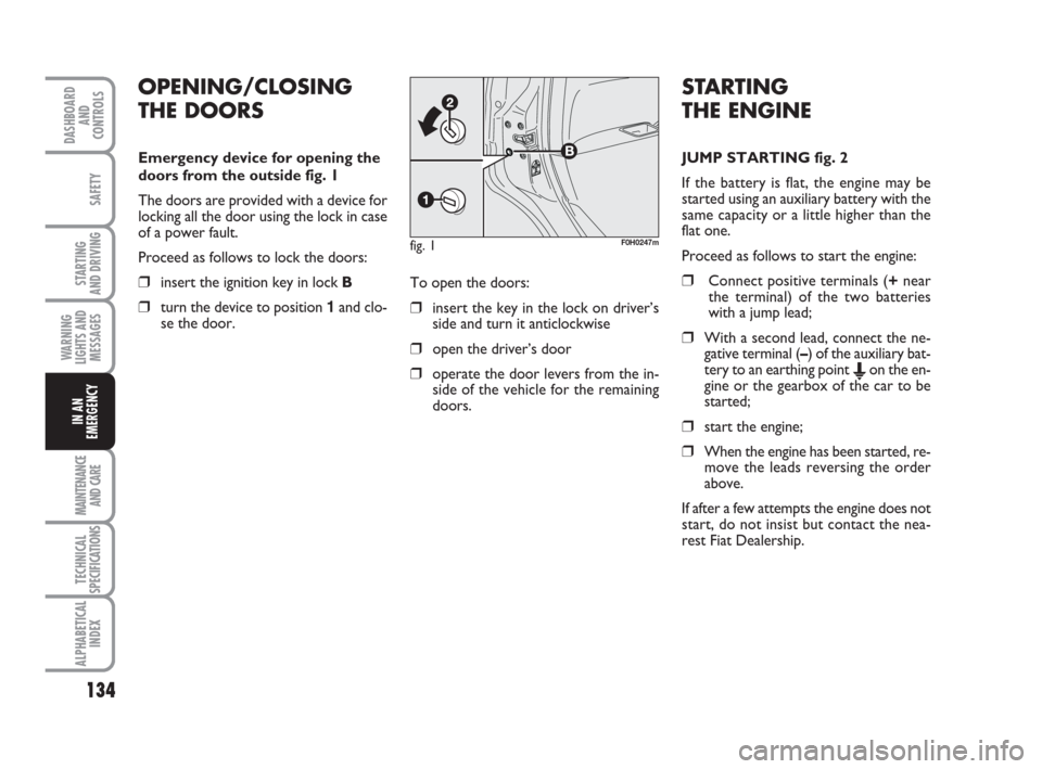
Emergency device for opening the
doors from the outside fig. 1
The doors are provided with a device for
locking all the door using the lock in case
of a power fault.
Proceed as follows to lock the doors:
❒insert the ignition key in lock B
❒turn the device to position 1and clo-
se the door.To open the doors:❒insert the key in the lock on driver’s
side and turn it anticlockwise
❒open the driver’s door
❒operate the door levers from the in-
side of the vehicle for the remaining
doors.
fig. 1F0H0247m
STARTING
THE ENGINE
JUMP STARTING fig. 2
If the battery is flat, the engine may be
started using an auxiliary battery with the
same capacity or a little higher than the
flat one.
Proceed as follows to start the engine:
❒Connect positive terminals (+near
the terminal) of the two batteries
with a jump lead;
❒With a second lead, connect the ne-
gative terminal (–) of the auxiliary bat-
tery to an earthing point
Eon the en-
gine or the gearbox of the car to be
started;
❒start the engine;
❒When the engine has been started, re-
move the leads reversing the order
above.
If after a few attempts the engine does not
start, do not insist but contact the nea-
rest Fiat Dealership.
Page 140 of 210
139
STARTING
AND DRIVING
MAINTENANCE
AND CARE
TECHNICAL
SPECIFICATIONS
ALPHABETICAL
INDEX
DASHBOARD
AND
CONTROLS
SAFETY
WARNING
LIGHTS AND
MESSAGES
IN AN
EMERGENCY
fig. 9F0H0749m
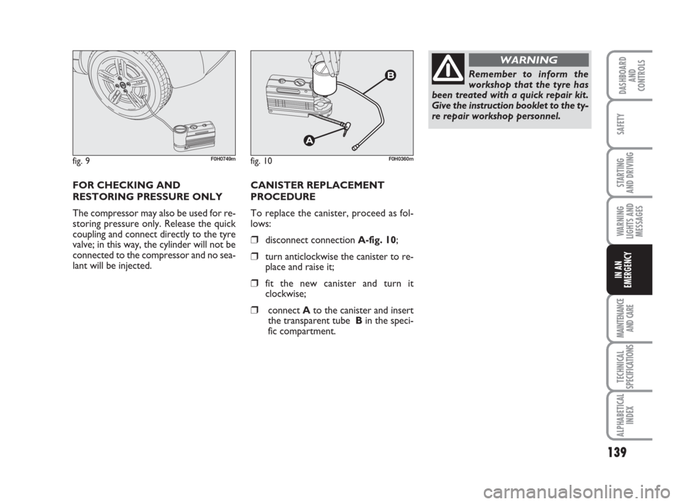
FOR CHECKING AND
RESTORING PRESSURE ONLY
The compressor may also be used for re-
storing pressure only. Release the quick
coupling and connect directly to the tyre
valve; in this way, the cylinder will not be
connected to the compressor and no sea-
lant will be injected.
fig. 10F0H0360m
CANISTER REPLACEMENT
PROCEDURE
To replace the canister, proceed as fol-
lows:
❒disconnect connection A-fig. 10;
❒turn anticlockwise the canister to re-
place and raise it;
❒fit the new canister and turn it
clockwise;
❒connect Ato the canister and insert
the transparent tube Bin the speci-
fic compartment.
Remember to inform the
workshop that the tyre has
been treated with a quick repair kit.
Give the instruction booklet to the ty-
re repair workshop personnel.
WARNING
Page 146 of 210
145
STARTING
AND DRIVING
MAINTENANCE
AND CARE
TECHNICAL
SPECIFICATIONS
ALPHABETICAL
INDEX
DASHBOARD
AND
CONTROLS
SAFETY
WARNING
LIGHTS AND
MESSAGES
IN AN
EMERGENCY
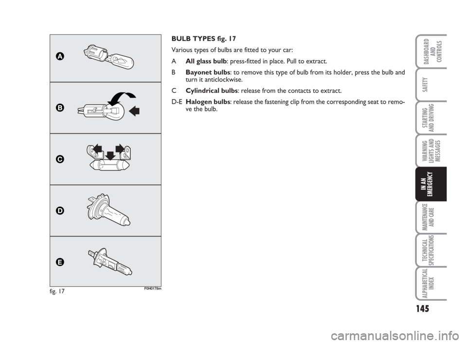
BULB TYPES fig. 17
Various types of bulbs are fitted to your car:
AAll glass bulb: press-fitted in place. Pull to extract.
BBayonet bulbs: to remove this type of bulb from its holder, press the bulb and
turn it anticlockwise.
CCylindrical bulbs: release from the contacts to extract.
D-EHalogen bulbs: release the fastening clip from the corresponding seat to remo-
ve the bulb.
fig. 17F0H0178m
Page 148 of 210
147
STARTING
AND DRIVING
MAINTENANCE
AND CARE
TECHNICAL
SPECIFICATIONS
ALPHABETICAL
INDEX
DASHBOARD
AND
CONTROLS
SAFETY
WARNING
LIGHTS AND
MESSAGES
IN AN
EMERGENCY
REPLACING EXTERIOR
BULBS
For the type of bulb and power rating, see
“When needing to change a bulb”.
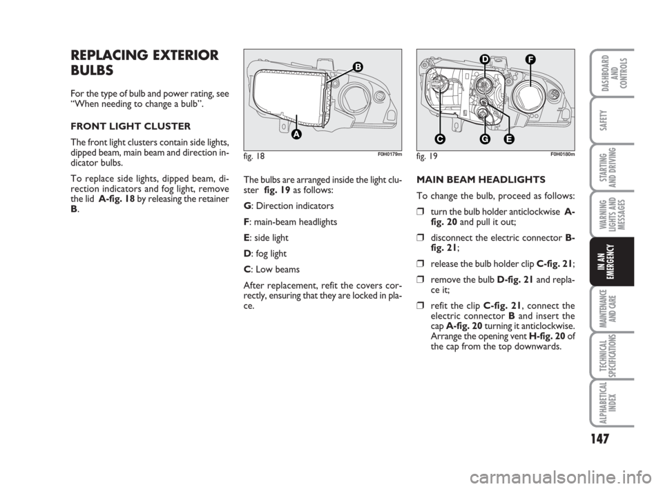
FRONT LIGHT CLUSTER
The front light clusters contain side lights,
dipped beam, main beam and direction in-
dicator bulbs.
To replace side lights, dipped beam, di-
rection indicators and fog light, remove
the lid A-fig. 18by releasing the retainer
B.
fig. 18F0H0179mfig. 19F0H0180m
The bulbs are arranged inside the light clu-
ster fig. 19as follows:
G: Direction indicators
F: main-beam headlights
E: side light
D: fog light
C: Low beams
After replacement, refit the covers cor-
rectly, ensuring that they are locked in pla-
ce.MAIN BEAM HEADLIGHTS
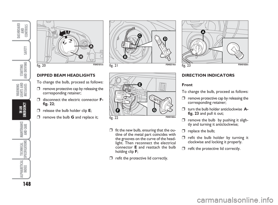
To change the bulb, proceed as follows:
❒turn the bulb holder anticlockwise A-
fig. 20and pull it out;
❒disconnect the electric connector B-
fig. 21;
❒release the bulb holder clip C-fig. 21;
❒remove the bulb D-fig. 21and repla-
ce it;
❒refit the clip C-fig. 21, connect the
electric connector Band insert the
cap A-fig. 20turning it anticlockwise.
Arrange the opening vent H-fig. 20of
the cap from the top downwards.
Page 149 of 210
148
STARTING
AND DRIVING
MAINTENANCE
AND CARE
TECHNICAL
SPECIFICATIONS
ALPHABETICAL
INDEX
DASHBOARD
AND
CONTROLS
SAFETY
WARNING
LIGHTS AND
MESSAGES
IN AN
EMERGENCY
fig. 20F0H0181mfig. 21
C
B
D
F0H0214m
fig. 22F0H0182m
DIPPED BEAM HEADLIGHTS
To change the bulb, proceed as follows:
❒remove protective cap by releasing the
corresponding retainer;
❒disconnect the electric connector F-
fig. 22;
❒release the bulb holder clip E;
❒remove the bulb Gand replace it;
fig. 23F0H0183m
DIRECTION INDICATORS
Front
To change the bulb, proceed as follows:
❒remove protective cap by releasing the
corresponding retainer;
❒turn the bulb holder anticlockwise A-
fig. 23and pull it out;
❒remove the bulb by pushing it sligh-
tly and turning it anticlockwise;
❒replace the bulb;
❒refit the bulb holder by turning it
clockwise and locking it properly.
❒refit the protective lid correctly.
❒fit the new bulb, ensuring that the ou-
tline of the metal part coincides with
the grooves on the curve of the head-
light. Then reconnect the electrical
connector Eand reattach the bulb
holding clip F;
❒refit the protective lid correctly.
Page 150 of 210
149
STARTING
AND DRIVING
MAINTENANCE
AND CARE
TECHNICAL
SPECIFICATIONS
ALPHABETICAL
INDEX
DASHBOARD
AND
CONTROLS
SAFETY
WARNING
LIGHTS AND
MESSAGES
IN AN
EMERGENCY
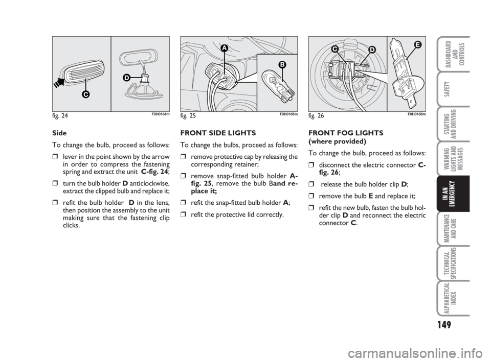
Side
To change the bulb, proceed as follows:
❒lever in the point shown by the arrow
in order to compress the fastening
spring and extract the unit C-fig. 24;
❒turn the bulb holder Danticlockwise,
extract the clipped bulb and replace it;
❒refit the bulb holder Din the lens,
then position the assembly to the unit
making sure that the fastening clip
clicks.
fig. 24F0H0184m
FRONT SIDE LIGHTS
To change the bulbs, proceed as follows:
❒remove protective cap by releasing the
corresponding retainer;
❒remove snap-fitted bulb holder A-
fig. 25, remove the bulb Band re-
place it;
❒refit the snap-fitted bulb holder A;
❒refit the protective lid correctly.FRONT FOG LIGHTS
(where provided)
To change the bulb, proceed as follows:
❒disconnect the electric connector C-
fig. 26;
❒release the bulb holder clip D;
❒remove the bulb Eand replace it;
❒refit the new bulb, fasten the bulb hol-
der clip Dand reconnect the electric
connector C.
fig. 25F0H0185mfig. 26F0H0186m