headlights FIAT IDEA 2009 1.G User Guide
[x] Cancel search | Manufacturer: FIAT, Model Year: 2009, Model line: IDEA, Model: FIAT IDEA 2009 1.GPages: 210, PDF Size: 3.62 MB
Page 117 of 210
116
WARNING
LIGHTS AND
MESSAGES
IN AN
EMERGENCY
MAINTENANCE
AND CARE
TECHNICAL
SPECIFICATIONS
ALPHABETICAL
INDEX
DASHBOARD
AND
CONTROLS
SAFETY
STARTING
AND DRIVING
CONTAINING
RUNNING COSTS
Here are some suggestions which may
help you to keep the running costs of your
vehicle down and lower the amount of
toxic emissions released into the atmo-
sphere.
GENERAL CONSIDERATIONS
Car maintenance
Have checks and adjustments carried out
in accordance with the “Service schedu-
le”.
Tyres
Check tyre pressure regularly, at least on-
ce every four weeks: excessively low pres-
sure will increase fuel consumption be-
cause rolling resistance will be higher.
Unnecessary loads
Do not travel with an overloaded boot.
Do not travel with too much luggage
stowed in the boot. The weight of the car
(especially when driving in town) and its
trim greatly affects consumption and sta-
bility.Roof rack/ski rack
Remove the roof rack or the ski rack from
the roof after use. These accessories de-
crease aerodynamic penetration of the car
and have a negative effect on consumption.
It is better to use a trailer to transport
particularly bulky objects.
Electrical devices
Use electrical devices only for the amount
of time needed. Rear heated window, ad-
ditional headlights, windscreen wipers and
heater fan need a considerable amount of
energy, therefore increasing the require-
ment of current increases fuel consump-
tion (up to +25% in the urban cycle).
Climate control
The climate control system requires hi-
gher fuel consumption (up to +20% in ave-
rage): use the air vents when the exter-
nal temperature allows to.
Spoilers
The use of non-certified aerodynamic
items may adversely affect air drag and fuel
consumption levels.DRIVING STYLE
Starting
Do not warm the engine up with the car
standing: the engine warms up very slowly
in these conditions, increasing fuel con-
sumption and emissions. It is advisable to
start off immediately and slowly keeping
the engine speed down: the engine will
warm up much faster this way.
Unnecessary actions
Avoid revving up when starting at traffic
lights or before stopping the engine. The
latter action, like doubling the clutch, is un-
necessary and causes increase of con-
sumption and pollution.
Gear selection
Use a higher gear as soon as traffic and
road conditions allow. Using a low gear
for faster acceleration will increase fuel
consumption.
In the same way improper use of a high
gear increases consumption, emissions an
engine wear.
Page 124 of 210
123
STARTING
AND DRIVING
IN AN
EMERGENCY
MAINTENANCE
AND CARE
TECHNICAL
SPECIFICATIONS
ALPHABETICAL
INDEX
DASHBOARD
AND
CONTROLS
SAFETY
WARNING
LIGHTS AND
MESSAGES
GENERAL WARNINGS ...................................................... 124
LOW BRAKE FLUID LEVEL ............................................... 124
HANDBRAKE APPLIED ...................................................... 124
AIRBAG FAILURE ................................................................. 124
HOT ENGINE COOLANT ............................................... 125
LOW BATTERY CHARGE................................................. 125
LOW ENGINE OIL PRESSURE -
EXHAUSTED OIL .............................................................. 126
“DUALDRIVE” ELECTRIC POWER STEERING
SYSTEM ................................................................................... 126
DOOR OPEN ........................................................................ 126
SEAT BELTS NOT FASTENED ........................................ 126
EBD FAILURE......................................................................... 127
EOBD/INJECTION SYSTEM FAILURE ............................ 127
FRONT PASSENGER AIRBAG DEACTIVATED ......... 128
ABS FAILURE ......................................................................... 128
FUEL RESERVE....................................................................... 128
GLOW PLUGS ...................................................................... 129
GLOW PLUG FAILURE ...................................................... 129
WATER IN DIESEL FUEL FILTER ..................................... 129
CAR PROTECTION SYSTEM
FAILURE - FIAT CODE ...................................................... 129
REAR FOG LIGHTS ............................................................. 129
GENERIC INDICATION .................................................... 130
WORN BRAKE PADS ......................................................... 131
W W
A A
R R
N N
I I
N N
G G
L L
I I
G G
H H
T T
S S
A A
N N
D D
M M
E E
S S
S S
A A
G G
E E
S S
OBSTRUCTED PARTICULATE TRAP ............................ 131
SIDE/TAIL LIGHTS AND
DIPPED BEAM HEADLIGHTS - FOLLOW ME HOME 131
FOG LIGHTS ......................................................................... 131
LEFT-HAND DIRECTION INDICATOR ....................... 131
RIGHT-HAND DIRECTION INDICATOR ................... 131
“DUALDRIVE” ELECTRIC POWER STEERING
SYSTEM ON .......................................................................... 132
CRUISE CONTROL ............................................................ 132
MAIN BEAM HEADLIGHTS............................................... 132
POSSIBLE ICE ON ROAD.................................................. 132
LIMITED RANGE .................................................................. 132
Page 133 of 210
132
STARTING
AND DRIVING
IN AN
EMERGENCY
MAINTENANCE
AND CARE
TECHNICAL
SPECIFICATIONS
ALPHABETICAL
INDEX
DASHBOARD
AND
CONTROLS
SAFETY
WARNING
LIGHTS AND
MESSAGES
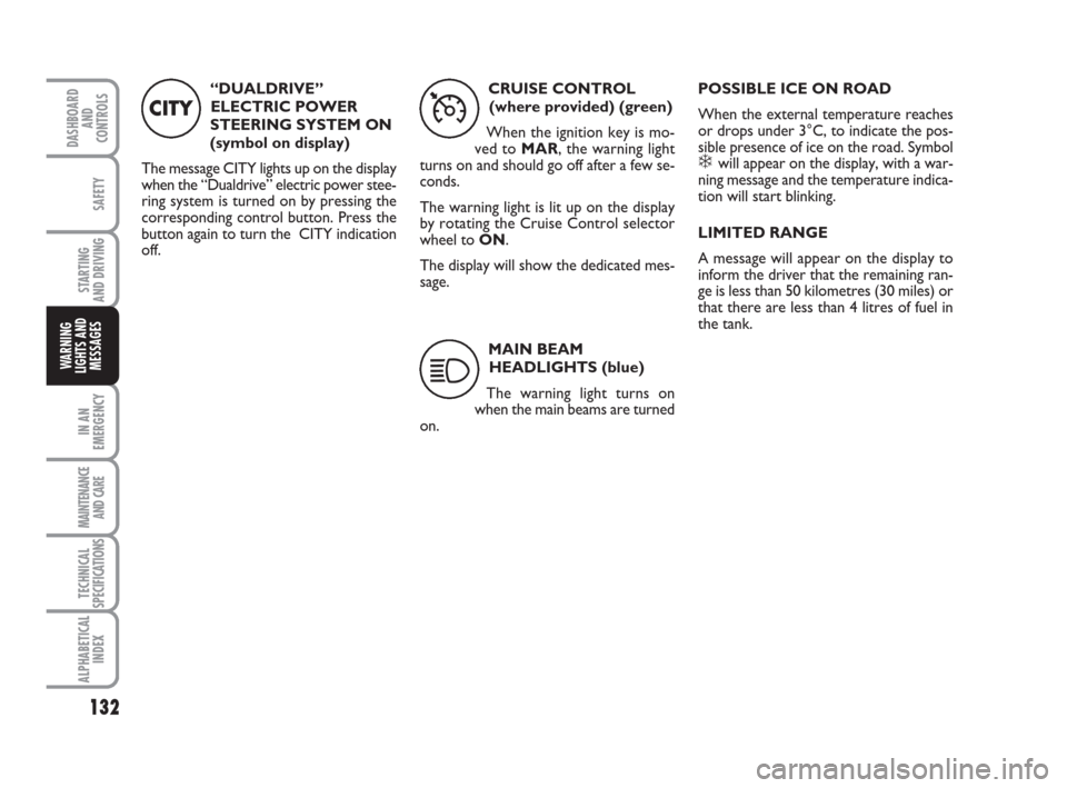
“DUALDRIVE”
ELECTRIC POWER
STEERING SYSTEM ON
(symbol on display)
The message CITY lights up on the display
when the “Dualdrive” electric power stee-
ring system is turned on by pressing the
corresponding control button. Press the
button again to turn the CITY indication
off.
CITY
CRUISE CONTROL
(where provided) (green)
When the ignition key is mo-
ved to MAR, the warning light
turns on and should go off after a few se-
conds.
The warning light is lit up on the display
by rotating the Cruise Control selector
wheel to ON.
The display will show the dedicated mes-
sage.
Ü
MAIN BEAM
HEADLIGHTS (blue)
The warning light turns on
when the main beams are turned
on.
1
POSSIBLE ICE ON ROAD
When the external temperature reaches
or drops under 3°C, to indicate the pos-
sible presence of ice on the road. Symbol
❄ will appear on the display, with a war-
ning message and the temperature indica-
tion will start blinking.
LIMITED RANGE
A message will appear on the display to
inform the driver that the remaining ran-
ge is less than 50 kilometres (30 miles) or
that there are less than 4 litres of fuel in
the tank.
Page 145 of 210
144
STARTING
AND DRIVING
MAINTENANCE
AND CARE
TECHNICAL
SPECIFICATIONS
ALPHABETICAL
INDEX
DASHBOARD
AND
CONTROLS
SAFETY
WARNING
LIGHTS AND
MESSAGES
IN AN
EMERGENCY
WHEN NEEDING TO
CHANGE A BULB
GENERAL INSTRUCTIONS
❒When a bulb is not working, check
that the corresponding fuse is intact
before replacing it: refer to the “If a fu-
se blows” paragraph in this chapter for
fuse location.
❒before changing a bulb check the con-
tacts for oxidation;
❒Burnt bulbs must be replaced by
others of the same type and power.
❒Always check the height of the head-
light beam after changing a bulb. Versions with alloy rims
❒Check that the hub contact surfaces
are clean;
❒fit the normal wheel centring it on the
pins, lead in the fastening screws and
tighten them using the wrench provi-
ded;
❒lower the car and remove the jack;
❒using the wrench provided, fully tigh-
ten the bolts in the sequence shown
in fig. 16.
❒snap fit the wheel cup on the hub.
When you have finished
❒stow the spare wheel C-fig. 11 in the
space provided in the boot;
❒Fit the jack partially open in its box B-
fig. 11forcing it lightly to prevent it
from vibrating when travelling;
❒put the tools back into their places in
the container;
❒arrange the container and tools in the
spare wheel and secure the fastening
device A-fig. 11;
❒rearrange the preformed boot cover
correctly.
Modifications or repairs to
the electrical system (elec-
tronic control units) that are not car-
ried out properly or do not take the
technical specifications of the system
into account can cause malfunctions
leading to the risk of fire.
WARNING
Halogen bulbs contain pres-
surised gas which may cau-
se small fragments of glass to be
projected outwards if the bulb is
broken.
WARNING
Halogen lamps must be hand-
led holding the metallic part
only. Touching the transpa-
rent part of the bulb with
your fingers may reduce the intensity
of the emitted light and even compro-
mise duration of the lamp itself. In the
case of accidental contact, rub the
lamp with a cloth and spirit and leave
to dry.IMPORTANT A slight misting may appear
on the internal surface of the headlight:
this does not indicate a fault and is cau-
sed by low temperature and the degree of
humidity in the air. Misting will rapidly di-
sappear when the headlights are switched
on. The presence of drops inside the head-
lights indicates infiltration of water. Go to
a Fiat Dealership.
Page 147 of 210
146
STARTING
AND DRIVING
MAINTENANCE
AND CARE
TECHNICAL
SPECIFICATIONS
ALPHABETICAL
INDEX
DASHBOARD
AND
CONTROLS
SAFETY
WARNING
LIGHTS AND
MESSAGES
IN AN
EMERGENCY
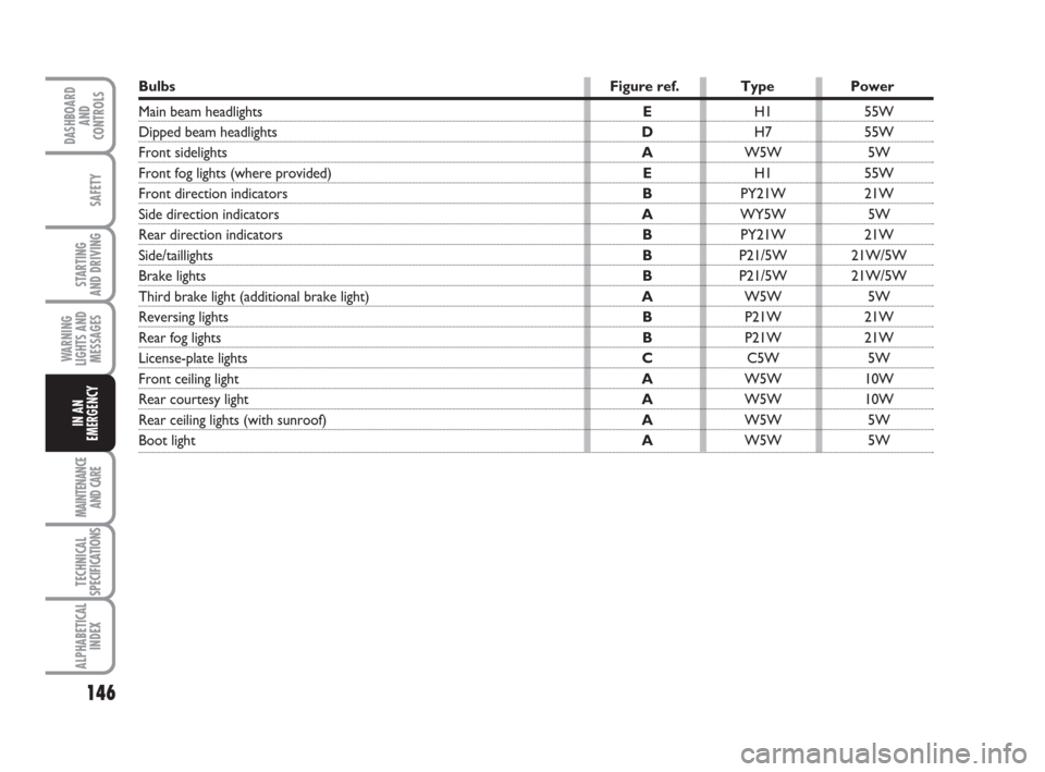
Bulbs Figure ref. Type Power
Main beam headlightsEH1 55W
Dipped beam headlights DH7 55W
Front sidelights AW5W 5W
Front fog lights (where provided)EH1 55W
Front direction indicators BPY21W 21W
Side direction indicators AWY5W 5W
Rear direction indicators BPY21W 21W
Side/taillights BP21/5W 21W/5W
Brake lights BP21/5W 21W/5W
Third brake light (additional brake light) AW5W 5W
Reversing lights BP21W 21W
Rear fog lights BP21W 21W
License-plate lights CC5W 5W
Front ceiling lightAW5W 10W
Rear courtesy lightAW5W 10W
Rear ceiling lights (with sunroof)AW5W 5W
Boot light AW5W 5W
Page 148 of 210
147
STARTING
AND DRIVING
MAINTENANCE
AND CARE
TECHNICAL
SPECIFICATIONS
ALPHABETICAL
INDEX
DASHBOARD
AND
CONTROLS
SAFETY
WARNING
LIGHTS AND
MESSAGES
IN AN
EMERGENCY
REPLACING EXTERIOR
BULBS
For the type of bulb and power rating, see
“When needing to change a bulb”.
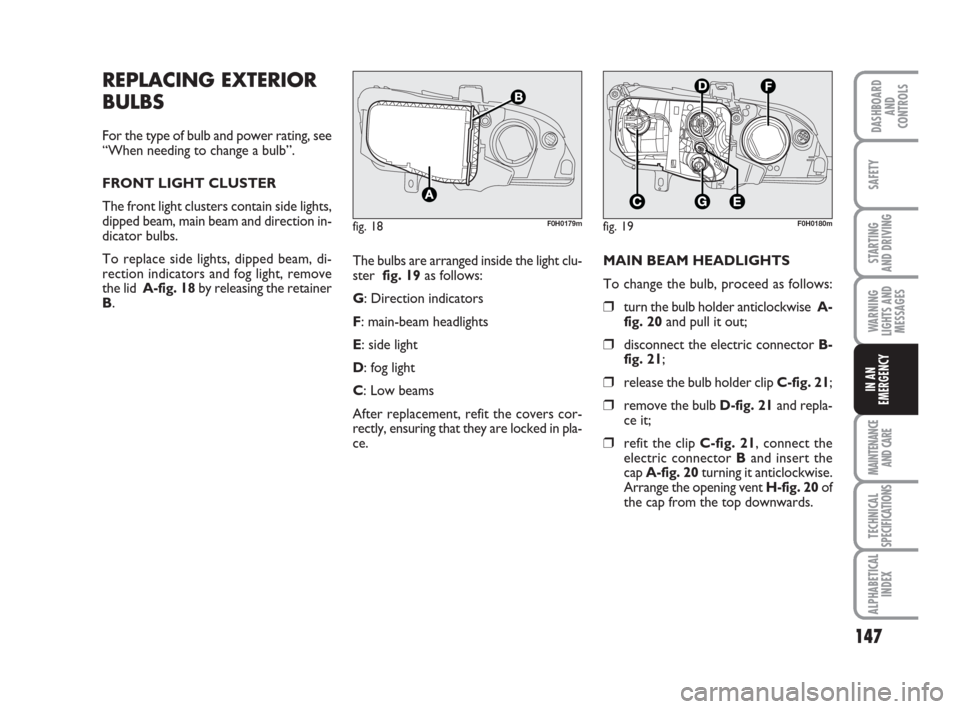
FRONT LIGHT CLUSTER
The front light clusters contain side lights,
dipped beam, main beam and direction in-
dicator bulbs.
To replace side lights, dipped beam, di-
rection indicators and fog light, remove
the lid A-fig. 18by releasing the retainer
B.
fig. 18F0H0179mfig. 19F0H0180m
The bulbs are arranged inside the light clu-
ster fig. 19as follows:
G: Direction indicators
F: main-beam headlights
E: side light
D: fog light
C: Low beams
After replacement, refit the covers cor-
rectly, ensuring that they are locked in pla-
ce.MAIN BEAM HEADLIGHTS
To change the bulb, proceed as follows:
❒turn the bulb holder anticlockwise A-
fig. 20and pull it out;
❒disconnect the electric connector B-
fig. 21;
❒release the bulb holder clip C-fig. 21;
❒remove the bulb D-fig. 21and repla-
ce it;
❒refit the clip C-fig. 21, connect the
electric connector Band insert the
cap A-fig. 20turning it anticlockwise.
Arrange the opening vent H-fig. 20of
the cap from the top downwards.
Page 149 of 210
148
STARTING
AND DRIVING
MAINTENANCE
AND CARE
TECHNICAL
SPECIFICATIONS
ALPHABETICAL
INDEX
DASHBOARD
AND
CONTROLS
SAFETY
WARNING
LIGHTS AND
MESSAGES
IN AN
EMERGENCY
fig. 20F0H0181mfig. 21
C
B
D
F0H0214m
fig. 22F0H0182m
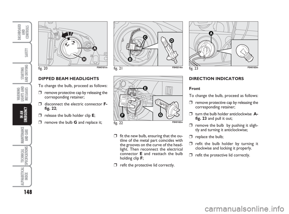
DIPPED BEAM HEADLIGHTS
To change the bulb, proceed as follows:
❒remove protective cap by releasing the
corresponding retainer;
❒disconnect the electric connector F-
fig. 22;
❒release the bulb holder clip E;
❒remove the bulb Gand replace it;
fig. 23F0H0183m
DIRECTION INDICATORS
Front
To change the bulb, proceed as follows:
❒remove protective cap by releasing the
corresponding retainer;
❒turn the bulb holder anticlockwise A-
fig. 23and pull it out;
❒remove the bulb by pushing it sligh-
tly and turning it anticlockwise;
❒replace the bulb;
❒refit the bulb holder by turning it
clockwise and locking it properly.
❒refit the protective lid correctly.
❒fit the new bulb, ensuring that the ou-
tline of the metal part coincides with
the grooves on the curve of the head-
light. Then reconnect the electrical
connector Eand reattach the bulb
holding clip F;
❒refit the protective lid correctly.
Page 158 of 210
157
STARTING
AND DRIVING
MAINTENANCE
AND CARE
TECHNICAL
SPECIFICATIONS
ALPHABETICAL
INDEX
DASHBOARD
AND
CONTROLS
SAFETY
WARNING
LIGHTS AND
MESSAGES
IN AN
EMERGENCY
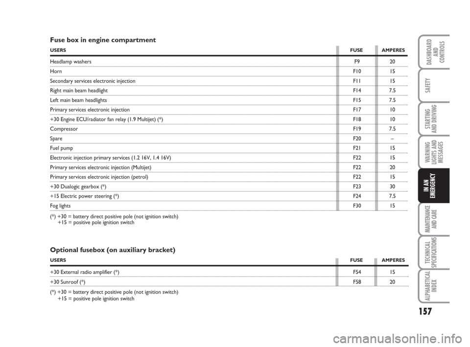
Fuse box in engine compartment
USERSFUSE AMPERES
Headlamp washersF9 20
HornF10 15
Secondary services electronic injectionF11 15
Right main beam headlightF14 7.5
Left main beam headlightsF15 7.5
Primary services electronic injectionF17 10
+30 Engine ECU/radiator fan relay (1.9 Multijet) (*)F18 10
CompressorF19 7.5
SpareF20 –
Fuel pumpF21 15
Electronic injection primary services (1.2 16V, 1.4 16V)F22 15
Primary services electronic injection (Multijet)F22 20
Primary services electronic injection (petrol)F22 15
+30 Dualogic gearbox (*)F23 30
+15 Electric power steering (*)F24 7.5
Fog lightsF30 15
(*) +30 = battery direct positive pole (not ignition switch)
+15 = positive pole ignition switch
Optional fusebox (on auxiliary bracket)
USERSFUSE AMPERES
+30 External radio amplifier (*)F54 15
+30 Sunroof (*)F58 20
(*) +30 = battery direct positive pole (not ignition switch)
+15 = positive pole ignition switch
Page 164 of 210
163
STARTING
AND DRIVING
IN AN
EMERGENCY
TECHNICAL
SPECIFICATIONS
ALPHABETICAL
INDEX
DASHBOARD
AND
CONTROLS
SAFETY
WARNING
LIGHTS AND
MESSAGES
MAINTENANCE
AND CARE
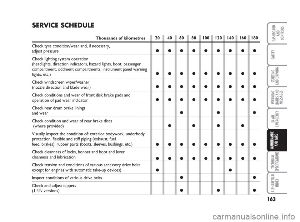
20 40 60 80 100 120 140 160 180
●●●●● ●●●●
●●●●● ●●●●
●●●●● ●●●●
●●●●● ●●●●
●●●
●● ● ●
●●●●● ●●●●
●●●●● ●●●●
●●
●●
●●●
SERVICE SCHEDULE
Thousands of kilometres
Check tyre condition/wear and, if necessary,
adjust pressure
Check lighting system operation
(headlights, direction indicators, hazard lights, boot, passenger
compartment, oddment compartments, instrument panel warning
lights, etc.)
Check windscreen wiper/washer
(nozzle direction and blade wear)
Check conditions and wear of front disk brake pads and
operation of pad wear indicator
Check rear drum brake linings
and wear
Check condition and wear of rear brake discs
(where provided)
Visually inspect the condition of: exterior bodywork, underbody
protection, flexible and stiff piping (exhaust, fuel
feed, brakes), rubber parts (boots, sleeves, bushings, etc.)
Check cleanness of locks, bonnet and boot and lever
cleanness and lubrication
Check tension and conditions of various accessory drive belts
except for engines with automatic take-up devices)
Inspect conditions of various drive belts
Check and adjust tappets
(1.48Vversions)
Page 180 of 210
179
STARTING
AND DRIVING
IN AN
EMERGENCY
TECHNICAL
SPECIFICATIONS
ALPHABETICAL
INDEX
DASHBOARD
AND
CONTROLS
SAFETY
WARNING
LIGHTS AND
MESSAGES
MAINTENANCE
AND CARE
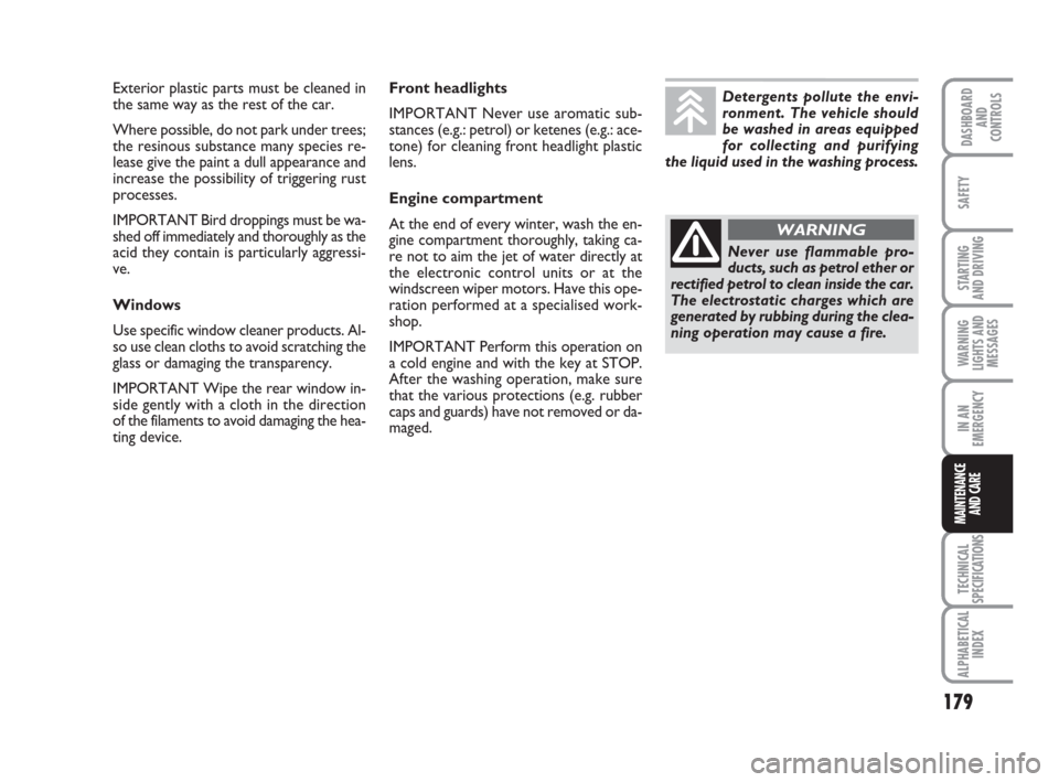
Exterior plastic parts must be cleaned in
the same way as the rest of the car.
Where possible, do not park under trees;
the resinous substance many species re-
lease give the paint a dull appearance and
increase the possibility of triggering rust
processes.
IMPORTANT Bird droppings must be wa-
shed off immediately and thoroughly as the
acid they contain is particularly aggressi-
ve.
Windows
Use specific window cleaner products. Al-
so use clean cloths to avoid scratching the
glass or damaging the transparency.
IMPORTANT Wipe the rear window in-
side gently with a cloth in the direction
of the filaments to avoid damaging the hea-
ting device.Front headlights
IMPORTANT Never use aromatic sub-
stances (e.g.: petrol) or ketenes (e.g.: ace-
tone) for cleaning front headlight plastic
lens.
Engine compartment
At the end of every winter, wash the en-
gine compartment thoroughly, taking ca-
re not to aim the jet of water directly at
the electronic control units or at the
windscreen wiper motors. Have this ope-
ration performed at a specialised work-
shop.
IMPORTANT Perform this operation on
a cold engine and with the key at STOP.
After the washing operation, make sure
that the various protections (e.g. rubber
caps and guards) have not removed or da-
maged.Detergents pollute the envi-
ronment. The vehicle should
be washed in areas equipped
for collecting and purifying
the liquid used in the washing process.
Never use flammable pro-
ducts, such as petrol ether or
rectified petrol to clean inside the car.
The electrostatic charges which are
generated by rubbing during the clea-
ning operation may cause a fire.
WARNING