instrument panel FIAT IDEA 2009 1.G Owners Manual
[x] Cancel search | Manufacturer: FIAT, Model Year: 2009, Model line: IDEA, Model: FIAT IDEA 2009 1.GPages: 210, PDF Size: 3.62 MB
Page 5 of 210
4
SAFETY
STARTING
AND DRIVING
WARNING
LIGHTS AND
MESSAGES
IN AN
EMERGENCY
MANUTENZIONE
E CURA
TECHNICAL
SPECIFICATIONS
ALPHABETICAL
INDEX
DASHBOARD
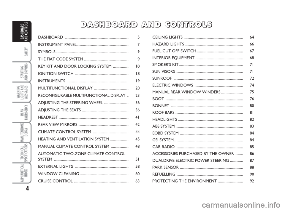
AND CONTROLSDASHBOARD ...................................................................... 5
INSTRUMENT PANEL......................................................... 7
SYMBOLS ................................................................................ 9
THE FIAT CODE SYSTEM ................................................. 9
KEY KIT AND DOOR LOCKING SYSTEM ................. 10
IGNITION SWITCH ........................................................... 18
INSTRUMENTS .................................................................... 19
MULTIFUNCTIONAL DISPLAY ...................................... 20
RECONFIGURABLE MULTIFUNCTIONAL DISPLAY .. 23
ADJUSTING THE STEERING WHEEL ........................... 36
ADJUSTING THE SEATS ................................................... 36
HEADREST ............................................................................ 41
REAR VIEW MIRRORS ....................................................... 42
CLIMATE CONTROL SYSTEM ....................................... 44
HEATING AND VENTILATION SYSTEM .................... 45
MANUAL CLIMATE CONTROL SYSTEM ................... 48
AUTOMATIC TWO-ZONE CLIMATE CONTROL
SYSTEM .................................................................................. 51
EXTERNAL LIGHTS ........................................................... 58
WINDOW CLEANING ..................................................... 60
CRUISE CONTROL ............................................................ 63CEILING LIGHTS ................................................................. 64
HAZARD LIGHTS ................................................................ 66
FUEL CUT OFF SWITCH................................................... 67
INTERIOR EQUIPMENT ................................................... 68
SMOKER’S KIT ...................................................................... 71
SUN VISORS ......................................................................... 71
SUNROOF ............................................................................ 72
ELECTRIC WINDOWS ..................................................... 74
MANUAL REAR WINDOW WINDERS ........................ 75
BOOT ..................................................................................... 76
BONNET ............................................................................... 80
ROOF BARS .......................................................................... 81
HEADLIGHTS ....................................................................... 82
ABS SYSTEM ......................................................................... 83
EOBD SYSTEM ..................................................................... 84
GSI SYSTEM............................................................................ 84
CAR RADIO ......................................................................... 85
ACCESSORIES PURCHASED BY THE OWNER ........ 86
DUALDRIVE ELECTRIC POWER STEERING .............. 87
PARK SENSOR ..................................................................... 88
REFUELLING ........................................................................ 90
PROTECTING THE ENVIRONMENT ........................... 92
D D
A A
S S
H H
B B
O O
A A
R R
D D
A A
N N
D D
C C
O O
N N
T T
R R
O O
L L
S S
Page 6 of 210
DASHBOARD
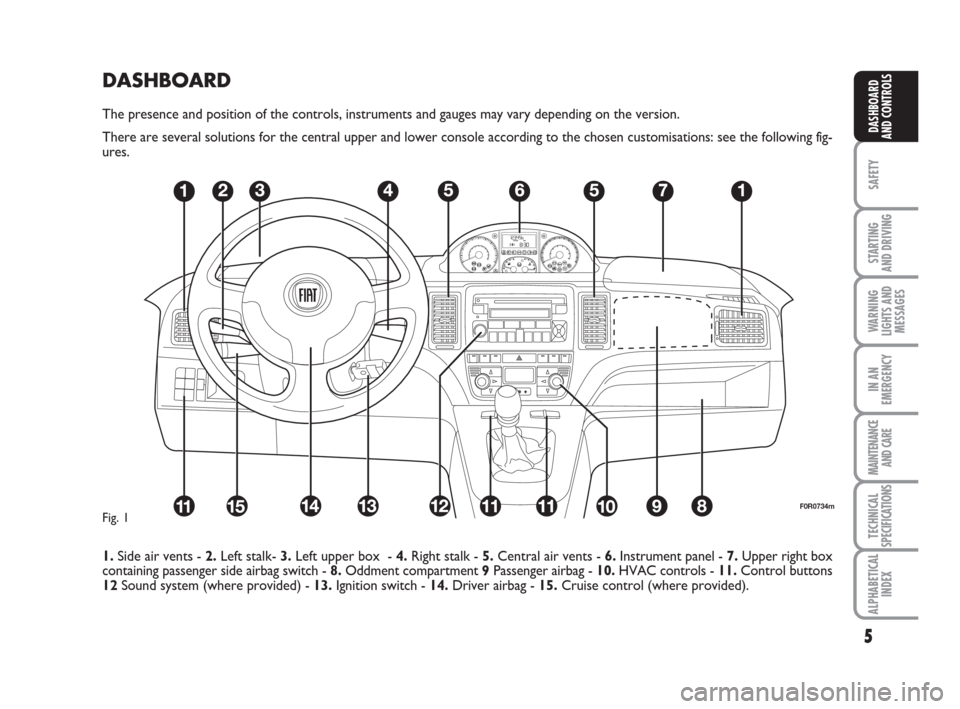
The presence and position of the controls, instruments and gauges may vary depending on the version.
There are several solutions for the central upper and lower console according to the chosen customisations: see the following fig-
ures.
1.Side air vents - 2.Left stalk- 3.Left upper box - 4.Right stalk - 5.Central air vents - 6.Instrument panel - 7.Upper right box
containing passenger side airbag switch - 8.Oddment compartment 9Passenger airbag - 10.HVAC controls - 11.Control buttons
12Sound system (where provided) - 13.Ignition switch - 14.Driver airbag - 15.Cruise control (where provided).
5
SAFETY
STARTING
AND DRIVING
WARNING
LIGHTS AND
MESSAGES
IN AN
EMERGENCY
MAINTENANCE
AND CARE
TECHNICAL
SPECIFICATIONS
ALPHABETICAL
INDEX
DASHBOARD
AND CONTROLS
F0R0734mFig. 1
Page 8 of 210
7
SAFETY
STARTING
AND DRIVING
WARNING
LIGHTS AND
MESSAGES
IN AN
EMERGENCY
MAINTENANCE
AND CARE
TECHNICAL
SPECIFICATIONS
ALPHABETICAL
INDEX
DASHBOARD
AND CONTROLS
F0H0706m
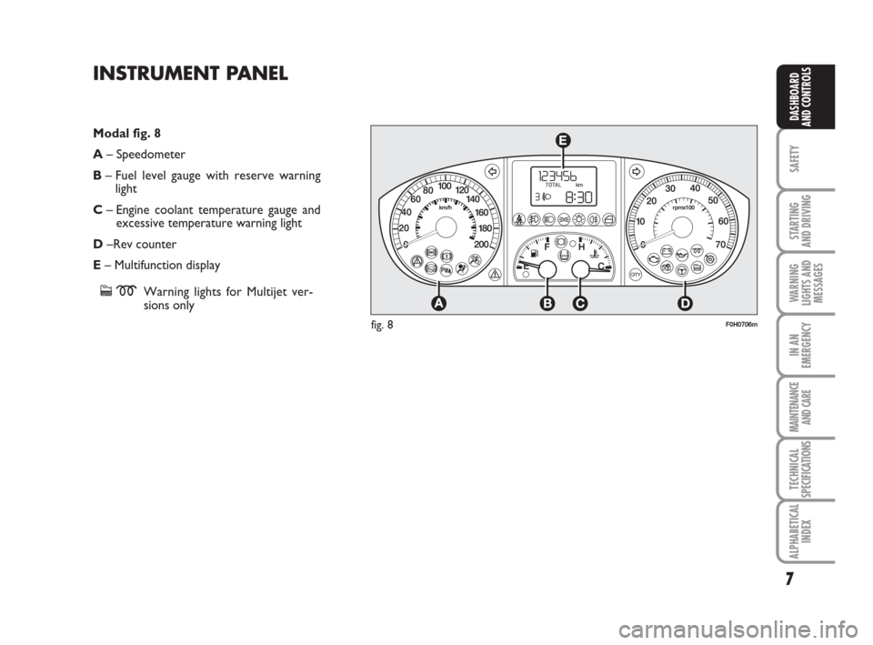
Modal fig. 8
A– Speedometer
B– Fuel level gauge with reserve warning
light
C– Engine coolant temperature gauge and
excessive temperature warning light
D–Rev counter
E– Multifunction display
cmWarning lights for Multijet ver-
sions only
INSTRUMENT PANEL
fig. 8
Page 25 of 210
24
SAFETY
STARTING
AND DRIVING
WARNING
LIGHTS AND
MESSAGES
IN AN
EMERGENCY
MAINTENANCE
AND CARE
TECHNICAL
SPECIFICATIONS
ALPHABETICAL
INDEX
DASHBOARD
AND CONTROLS
Headlight adjustment (only
with dipped beam headlights on)
– when the standard page is displayed, this
is used to adjust the headlights (see the
“Headlights” paragraph in this chapter).
Setup menu
– for scrolling the menu up and down;
– to increase or decrease values during
settings.
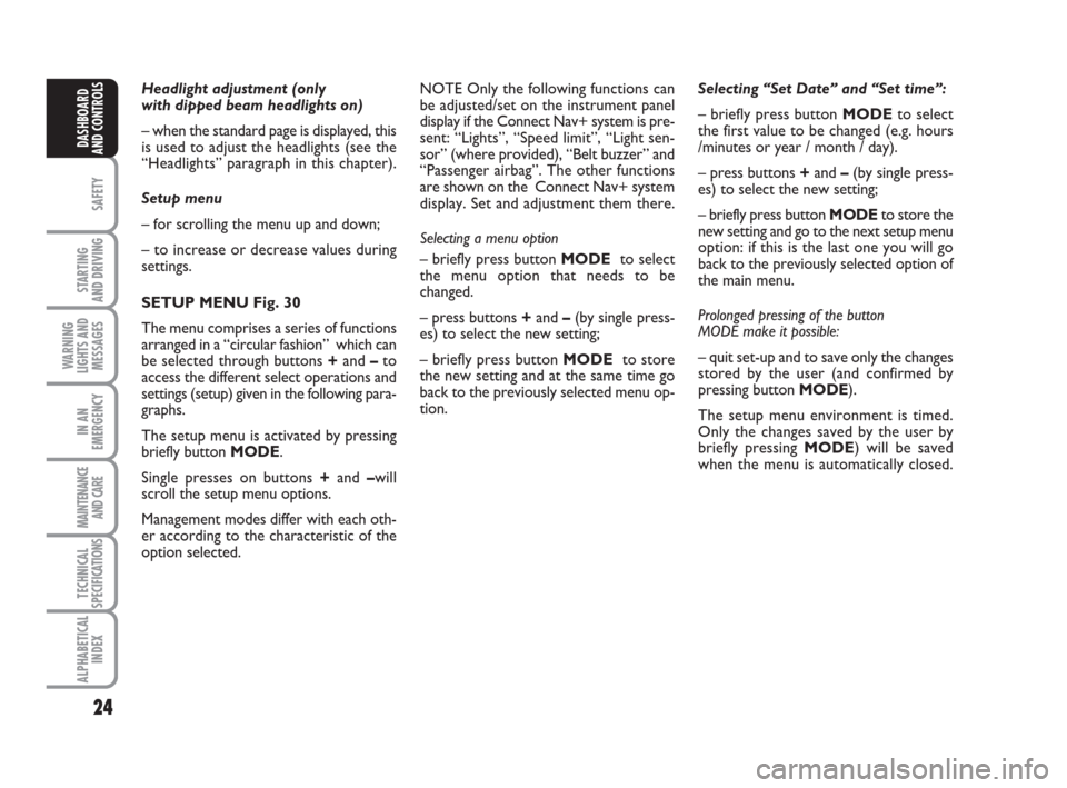
SETUP MENU Fig. 30
The menu comprises a series of functions
arranged in a “circular fashion” which can
be selected through buttons +and –to
access the different select operations and
settings (setup) given in the following para-
graphs.
The setup menu is activated by pressing
briefly button MODE.
Single presses on buttons +and –will
scroll the setup menu options.
Management modes differ with each oth-
er according to the characteristic of the
option selected.Selecting “Set Date” and “Set time”:
– briefly press button MODEto select
the first value to be changed (e.g. hours
/minutes or year / month / day).
– press buttons +and –(by single press-
es) to select the new setting;
– briefly press button MODEto store the
new setting and go to the next setup menu
option: if this is the last one you will go
back to the previously selected option of
the main menu.
Prolonged pressing of the button
MODE make it possible:
– quit set-up and to save only the changes
stored by the user (and confirmed by
pressing button MODE).
The setup menu environment is timed.
Only the changes saved by the user by
briefly pressing MODE) will be saved
when the menu is automatically closed. NOTE Only the following functions can
be adjusted/set on the instrument panel
display if the Connect Nav+ system is pre-
sent: “Lights”, “Speed limit”, “Light sen-
sor” (where provided), “Belt buzzer” and
“Passenger airbag”. The other functions
are shown on the Connect Nav+ system
display. Set and adjustment them there.
Selecting a menu option
– briefly press button MODEto select
the menu option that needs to be
changed.
– press buttons +and –(by single press-
es) to select the new setting;
– briefly press button MODEto store
the new setting and at the same time go
back to the previously selected menu op-
tion.
Page 59 of 210
58
SAFETY
STARTING
AND DRIVING
WARNING
LIGHTS AND
MESSAGES
IN AN
EMERGENCY
MAINTENANCE
AND CARE
TECHNICAL
SPECIFICATIONS
ALPHABETICAL
INDEX
DASHBOARD
AND CONTROLS
EXTERNAL LIGHTS
The left-hand lever includes the controls
for the external lights.
The external lights can only be switched
on when the ignition key is at MAR.
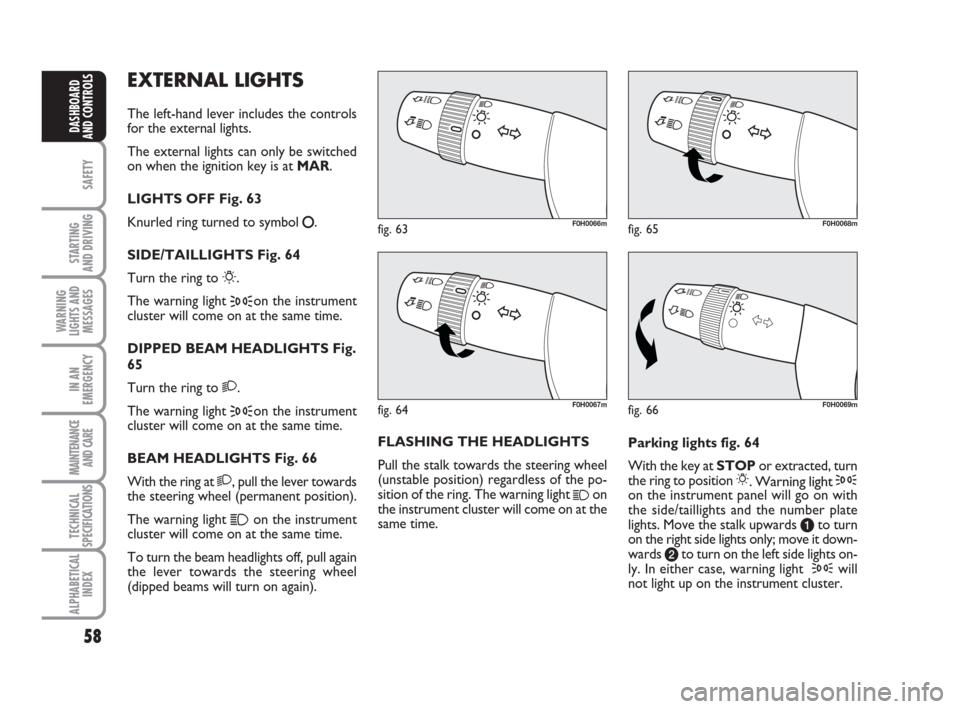
LIGHTS OFF Fig. 63
Knurled ring turned to symbol
å.
SIDE/TAILLIGHTS Fig. 64
Turn the ring to
6.
The warning light
3on the instrument
cluster will come on at the same time.
DIPPED BEAM HEADLIGHTS Fig.
65
Turn the ring to 2.
The warning light
3on the instrument
cluster will come on at the same time.
BEAM HEADLIGHTS Fig. 66
With the ring at 2, pull the lever towards
the steering wheel (permanent position).
The warning light
1on the instrument
cluster will come on at the same time.
To turn the beam headlights off, pull again
the lever towards the steering wheel
(dipped beams will turn on again).FLASHING THE HEADLIGHTS
Pull the stalk towards the steering wheel
(unstable position) regardless of the po-
sition of the ring. The warning light
1on
the instrument cluster will come on at the
same time.Parking lights fig. 64
With the key at STOPor extracted, turn
the ring to position 6. Warning light 3on the instrument panel will go on with
the side/taillights and the number plate
lights. Move the stalk upwards ato turn
on the right side lights only; move it down-
wards bto turn on the left side lights on-
ly. In either case, warning light
3will
not light up on the instrument cluster.
fig. 63F0H0066m
fig. 66F0H0069m
fig. 65F0H0068m
fig. 64F0H0067m
Page 60 of 210
59
SAFETY
STARTING
AND DRIVING
WARNING
LIGHTS AND
MESSAGES
IN AN
EMERGENCY
MAINTENANCE
AND CARE
TECHNICAL
SPECIFICATIONS
ALPHABETICAL
INDEX
DASHBOARD
AND CONTROLS
fig. 67F0H0071mfig. 68F0H0070mfig. 69F0H0072m
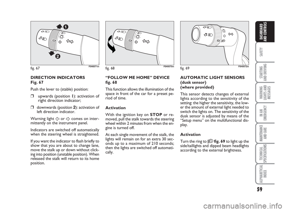
DIRECTION INDICATORS
Fig. 67
Push the lever to (stable) position:
❒upwards (position 11): activation of
right direction indicator;
❒
downwards (position 2): activation of
left direction indicator.
Warning light
ForDcomes on inter-
mittently on the instrument panel.
Indicators are switched off automatically
when the steering wheel is straightened.
If you want the indicator to flash briefly to
show that you are about to change lane,
move the stalk up or down without click-
ing into position (unstable position). When
released the stalk will return to its home
position.“FOLLOW ME HOME” DEVICE
fig. 68
This function allows the illumination of the
space in front of the car for a preset pe-
riod of time.
Activation
With the ignition key on STOPor re-
moved, pull the stalk towards the steering
wheel within 2 minutes from when the en-
gine is turned off.
At each single movement of the stalk, the
lights will remain on for an extra 30 sec-
onds up to a maximum of 210 seconds;
then the lights are switched off automati-
cally. AUTOMATIC LIGHT SENSORS
(dusk sensor)
(where provided)
This sensor detects changes of external
lights according to the sensitivity of the
setting: the higher the sensitivity, the low-
er the amount of external light needed to
switch the lights on. The sensitivity of the
dusk sensor is adjusted by means of the
“Setup menu” on the multifunctional dis-
play.
Activation
Turn the ring to
2Afig. 69to light up the
side/taillights and dipped beam headlights
according to the external brightness.
Page 64 of 210

63
SAFETY
STARTING
AND DRIVING
WARNING
LIGHTS AND
MESSAGES
IN AN
EMERGENCY
MAINTENANCE
AND CARE
TECHNICAL
SPECIFICATIONS
ALPHABETICAL
INDEX
DASHBOARD
AND CONTROLS
CRUISE CONTROL
(constant speed
regulator) (where
provided)
It is a device able to support the driver,
with electronic control, which allows dri-
ving at speed over 30 km/h on long and
straight dry roads (e.g.: motorways), at a
desired speed, without pressing the ac-
celerator pedal. Therefore it is not sug-
gested to use this device on extra-urban
roads with traffic. Do not use it in town.
TURING THE DEVICE ON
Turn the ring A-fig. 75to ON.
The device can be turned on in 4th or 5th
gear only. Travelling downhill with the de-
vice engaged, the car speed may increase
more than the memorised one.
When the device is activated the warn-
ing light
Üturns on together with the rel-
evant message on the instrument panel
(where provided).
fig. 75F0H0074m
STORING THE SPEED
Proceed as follows:
❒turn ring A-fig. 75to ONand press
the accelerator pedal to the required
speed;
❒push the lever upwards (+) for at
least 1 second, then release it: the
car speed will be stored. The accel-
erator pedal may be released.
If needed (e.g. for overtaking), press the
accelerator pedal to accelerate: the car
will return to the previously set speed
when the pedal is released.RESTORING MEMORIZED
SPEED
If the device has been disengaged, for ex-
ample by pressing the brake or clutch ped-
al, the memorized speed can be reset as
follows:
❒accelerate gradually until reaching a
speed approaching the stored speed;
❒engage the gear selected when the
speed was stored (4th or 5th gear);
❒press button RES B-fig. 75.
INCREASING THE MEMORIZED
SPEED
The stored speed can be increased in two
ways:
❒by pressing the accelerator and then
storing the new speed reached;
or
❒ by moving the stalk upwards (+).
Each operation of the stalk will correspond
to a slight increase in speed (about 1 km/h),
while keeping the stalk upwards will cor-
respond to a continuous speed increase.
When travelling with the de-
vice on, never set the
gearshift lever to neutral.
WARNING
Page 77 of 210
76
SAFETY
STARTING
AND DRIVING
WARNING
LIGHTS AND
MESSAGES
IN AN
EMERGENCY
MAINTENANCE
AND CARE
TECHNICAL
SPECIFICATIONS
ALPHABETICAL
INDEX
DASHBOARD
AND CONTROLS
BOOT
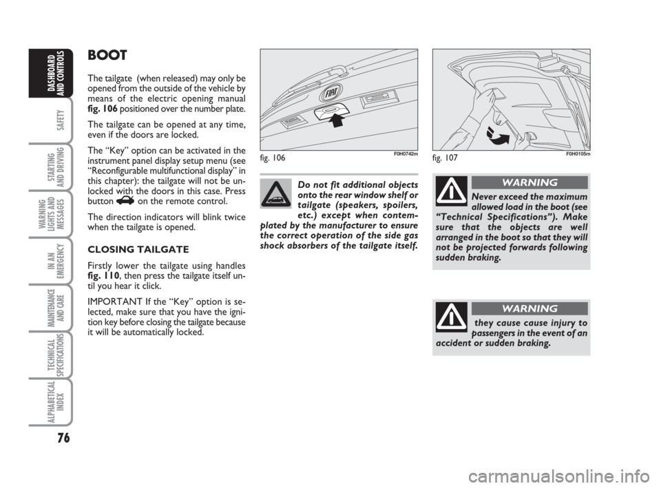
The tailgate (when released) may only be
opened from the outside of the vehicle by
means of the electric opening manual
fig. 106 positioned over the number plate.
The tailgate can be opened at any time,
even if the doors are locked.
The “Key” option can be activated in the
instrument panel display setup menu (see
“Reconfigurable multifunctional display” in
this chapter): the tailgate will not be un-
locked with the doors in this case. Press
button
Ron the remote control.
The direction indicators will blink twice
when the tailgate is opened.
CLOSING TAILGATE
Firstly lower the tailgate using handles
fig. 110, then press the tailgate itself un-
til you hear it click.
IMPORTANT If the “Key” option is se-
lected, make sure that you have the igni-
tion key before closing the tailgate because
it will be automatically locked.
fig. 106F0H0742m
Do not fit additional objects
onto the rear window shelf or
tailgate (speakers, spoilers,
etc.) except when contem-
plated by the manufacturer to ensure
the correct operation of the side gas
shock absorbers of the tailgate itself.
Never exceed the maximum
allowed load in the boot (see
“Technical Specifications”). Make
sure that the objects are well
arranged in the boot so that they will
not be projected forwards following
sudden braking.
WARNING
they cause cause injury to
passengers in the event of an
accident or sudden braking.
WARNING
fig. 107F0H0105m
Page 84 of 210
83
SAFETY
STARTING
AND DRIVING
WARNING
LIGHTS AND
MESSAGES
IN AN
EMERGENCY
MAINTENANCE
AND CARE
TECHNICAL
SPECIFICATIONS
ALPHABETICAL
INDEX
DASHBOARD
AND CONTROLS
ABS SYSTEM
If you have never driven a vehicle with
ABS before, it is advisable to perform a
few tests on slippery ground, naturally in
conditions of safety and respecting the
Highway Code of the country where you
are driving. Read the following informa-
tion carefully.
The car is fitted with an ABS braking sys-
tem, which prevents the wheels from lock-
ing when braking, makes the most of road
grip and gives the best control when
emergency braking under difficulty road
conditions.
System is completed by EBD (Electronic
Braking force Distribution), which dis-
tributes the braking action between front
and rear wheels.
IMPORTANT The braking system needs
to settle for approximately 500 km: dur-
ing this time, avoid sudden, repeated and
prolonged braking.ABS SYSTEM INTERVENTION
Intervention of the ABS is detected by a
slight pulsing of the brake pedal accom-
panied by noise: such an event indicates
that you need to adjust your speed to the
type of road on which you are travelling.
When the ABS intervenes it means that
you are approaching the grip limit be-
tween tyres and road: slow down to ex-
ploit all the available grip.
FAILURE INDICATIONS
ABS failure
ABS failure is indicated by the turning on
of warning light
>on the instrument pan-
el together with the dedicated message on
the multifunctional display (where pro-
vided), (see section “Warning lights and
messages”). In the case, the braking sys-
tem will work as normal without the ex-
tra potentials offered by the ABS system.
Drive carefully to the nearest Fiat Deal-
ership to have the system checked.EBD failure
ABS failure is indicated by the turning on
of warning light >and xon the instru-
ment panel together with the dedicated
message on the multifunctional display
(where provided), (see section “Warning
lights and messages”). In this case, the rear
wheels may suddenly lock and the vehi-
cle may swerve when braking sharply. Dri-
ve carefully to the nearest Fiat Dealership
to have the system checked.
When the ABS intervenes it
means that you are ap-
proaching the grip limit between tyres
and road: slow down to exploit all the
available grip.
WARNING
The ABS exploits the tyre-
road grip at the best, but it
cannot improve it; you should there-
fore take every care when driving on
slippery surfaces without taking un-
necessary risks.
WARNING
When the ABS cuts in, and
you feel the brake pedal pul-
sating, do not remove your foot, but
keep it pressed; in doing so you will
stop in the shortest amount of space
possible under the current road con-
ditions.
WARNING
Page 85 of 210
84
SAFETY
STARTING
AND DRIVING
WARNING
LIGHTS AND
MESSAGES
IN AN
EMERGENCY
MAINTENANCE
AND CARE
TECHNICAL
SPECIFICATIONS
ALPHABETICAL
INDEX
DASHBOARD
AND CONTROLS
If warning light xonly lights
up on the instrument panel
(with a message on the reconfigurable
multifunctional display, where pro-
vided), stop the car immediately and
go to the nearest Fiat Dealership.
Leakage of hydraulic fluid from the
braking system will compromise func-
tionality of the braking system, either
of the conventional type or with ABS.
WARNINGEOBD SYSTEM
The EOBD system (European On Board
Diagnosis) allows continuous diagnosis of
the components of the car correlated with
emissions. It also alerts the driver, by turn-
ing on the warning light
Uon the in-
strument panel (together with relevant
message on the multifunctional display,
where provided) (see section “Warning
lights and messages”), when these condi-
tions are no longer in peak conditions.
The objective is:
❒to keep the system efficiency under
control;
❒warn when a fault causes emissions
levels to increase;
❒warn of the need to replace deterio-
rated components.
The system also has a diagnostic connec-
tor that can be interfaced with appropri-
ate tools, which makes it possible to read
the error codes stored in the control unit
together with a series of specific parame-
ters for engine operation and diagnosis.
This check can also be carried out by the
traffic police.
IMPORTANT After eliminating the in-
convenience, to check the system com-
pletely, Fiat Dealerships are obliged to run
a bench test and, if necessary, road tests
which may also call for a long journey. Go to a Fiat Dealership as
soon as possible if warning
light
Ueither does not light
up when the key is turned to
MAR to if while travelling the warning
lights comes on either steady or blink-
ing (along with a message on the mul-
tifunctional display, where provided).
The operation of warning light
Umay
be checked by the traffic police using
specific devices. Follow the laws in
force in the country where you are dri-
ving.
GSI SYSTEM
(for versions with
mechanical gearbox
only)
(where provided)
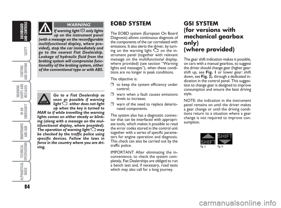
The gear shift indication makes it possible,
on cars with a manual gearbox, to suggest
the driver should change gear (higher gear:
shift up, see Fig. 1or lower gear: shift
down, see Fig. 2), through a dedicated in-
dication in the control panel. This sugges-
tion to change gear is designed to improve
consumption and ensure the best driving
style.
NOTE: the indication in the instrument
panel remains on until the driver makes
a gear change or until the driving condi-
tions return to a situation where a gear
change is not required to improve con-
sumption.
fig. a fig. b