ESP FIAT IDEA 2009 1.G Owner's Manual
[x] Cancel search | Manufacturer: FIAT, Model Year: 2009, Model line: IDEA, Model: FIAT IDEA 2009 1.GPages: 210, PDF Size: 3.62 MB
Page 114 of 210
113
WARNING
LIGHTS AND
MESSAGES
IN AN
EMERGENCY
MAINTENANCE
AND CARE
TECHNICAL
SPECIFICATIONS
ALPHABETICAL
INDEX
DASHBOARD
AND
CONTROLS
SAFETY
STARTING
AND DRIVING
❒turn the ignition key to AVVas soon
as the warning light mturns off.
Waiting too long will waste the work
done by the heater plugs. Release the
key as soon as the engine starts.
IMPORTANT With the engine cold, the
accelerator must be entirely released
when turning the ignition key to position
AVV.
If the engine does not start at the first at-
tempt, return the ignition key to STOP
before repeating starting.
If, when the ignition key is at MAR, the
instrument panel warning light
Yre-
mains lit, turn the key to STOPand then
back to MAR; if the warning lights remain
on, try with the other keys provided with
the car.
Contact a Fiat Dealership if you still can-
not start the engine.
IMPORTANT Never leave the ignition key
to MARwhen the engine is off. Warning light
mwill blink
for 60 seconds after starting
or during prolonged cranking
to indicate a fault to the glow
plug heating system. Use the car nor-
mally if the engine starts and go to a
Fiat Dealership as soon as possible.
HOW TO WARM UP THE
ENGINE AFTER IT HAS JUST
STARTED (petrol and Multijet
engines)
Proceed as follows:
❒drive off slowly, letting the engine turn
at medium speed. Do not accelerate
abruptly;
❒do not demand maximum performan-
ce for the first few kilometres. Wait
until the engine coolant gauge starts
moving.
STOPPING THE ENGINE
Turn the ignition to STOPwhile the en-
gine is idling.
IMPORTANT After a taxing drive, you
should allow the engine to “catch its
breath” before turning it off by letting it
idle to allow the temperature in the engi-
ne compartment to fall. Never jump start the engine
by pushing, towing or driving
downhill. This could cause a
flow of fuel into the catalytic
converter and damage it beyond re-
pair.
A quick burst on the accele-
rator before turning off the
engine serves absolutely no
practical purpose, it wastes
fuel and is damaging especially to tur-
bocharged engines.
Remember that the brake
booster and power steering
are not operational until the engine
has been started, therefore much
effort than usual is required on the
brake pedal and steering wheel.
WARNING
Page 117 of 210
116
WARNING
LIGHTS AND
MESSAGES
IN AN
EMERGENCY
MAINTENANCE
AND CARE
TECHNICAL
SPECIFICATIONS
ALPHABETICAL
INDEX
DASHBOARD
AND
CONTROLS
SAFETY
STARTING
AND DRIVING
CONTAINING
RUNNING COSTS
Here are some suggestions which may
help you to keep the running costs of your
vehicle down and lower the amount of
toxic emissions released into the atmo-
sphere.
GENERAL CONSIDERATIONS
Car maintenance
Have checks and adjustments carried out
in accordance with the “Service schedu-
le”.
Tyres
Check tyre pressure regularly, at least on-
ce every four weeks: excessively low pres-
sure will increase fuel consumption be-
cause rolling resistance will be higher.
Unnecessary loads
Do not travel with an overloaded boot.
Do not travel with too much luggage
stowed in the boot. The weight of the car
(especially when driving in town) and its
trim greatly affects consumption and sta-
bility.Roof rack/ski rack
Remove the roof rack or the ski rack from
the roof after use. These accessories de-
crease aerodynamic penetration of the car
and have a negative effect on consumption.
It is better to use a trailer to transport
particularly bulky objects.
Electrical devices
Use electrical devices only for the amount
of time needed. Rear heated window, ad-
ditional headlights, windscreen wipers and
heater fan need a considerable amount of
energy, therefore increasing the require-
ment of current increases fuel consump-
tion (up to +25% in the urban cycle).
Climate control
The climate control system requires hi-
gher fuel consumption (up to +20% in ave-
rage): use the air vents when the exter-
nal temperature allows to.
Spoilers
The use of non-certified aerodynamic
items may adversely affect air drag and fuel
consumption levels.DRIVING STYLE
Starting
Do not warm the engine up with the car
standing: the engine warms up very slowly
in these conditions, increasing fuel con-
sumption and emissions. It is advisable to
start off immediately and slowly keeping
the engine speed down: the engine will
warm up much faster this way.
Unnecessary actions
Avoid revving up when starting at traffic
lights or before stopping the engine. The
latter action, like doubling the clutch, is un-
necessary and causes increase of con-
sumption and pollution.
Gear selection
Use a higher gear as soon as traffic and
road conditions allow. Using a low gear
for faster acceleration will increase fuel
consumption.
In the same way improper use of a high
gear increases consumption, emissions an
engine wear.
Page 119 of 210
118
WARNING
LIGHTS AND
MESSAGES
IN AN
EMERGENCY
MAINTENANCE
AND CARE
TECHNICAL
SPECIFICATIONS
ALPHABETICAL
INDEX
DASHBOARD
AND
CONTROLS
SAFETY
STARTING
AND DRIVING
Respect the speed limits specific for each
country for vehicles towing trailers. In all
cases, the top speed must not exceed 100
km/h.
The ABS with which the car
may be equipped will not
control the braking system of the trai-
ler. Particular caution is required on
slippery roads.
Never modify the braking sy-
stem of the car to control
the trailer brake. The trailer braking
system must be fully independent
from the hydraulic system of the car.
WARNING
WARNING
INSTALLING THE TOW HOOK
The towing device should be fastened to
the body by specialised personnel accor-
ding to any additional and/or integrative
information supplied by the Manufacturer
of the device.
The towing device must meet current re-
gulations with reference to 94/20/EC Di-
rective and subsequent amendments.
For any version the towing device used
must match the towable weight of the car
on which it is to be installed.
For the electric connection a unified con-
nector should be used which is generally
placed on a special bracket normally fa-
stened to the towing device, and a spe-
cial ECU for external trailer light control
shall be installed on the car. For the electrical connection, 7 or 13 pin
12VDC connection is to be used (CU-
NA/UNI and ISO/DIN Standards). Follow
the instructions provided by the car ma-
nufacturer and/or the tow hitch manufac-
turer.
An electric brake should be supplied di-
rectly by the battery through a cable with
a cross section of no less than 2.5 mm2,5.
IMPORTANT Electric brake or other de-
vice shall be used with running engine.
In addition to the electrical branches, the
car’s electric system can only be connec-
ted to the supply cable for an electric
brake and to the cable for an internal li-
ght, though not above 15W.
For connections use the preset control
unit with battery cable no less than 2.5
mm
2.
Page 133 of 210
132
STARTING
AND DRIVING
IN AN
EMERGENCY
MAINTENANCE
AND CARE
TECHNICAL
SPECIFICATIONS
ALPHABETICAL
INDEX
DASHBOARD
AND
CONTROLS
SAFETY
WARNING
LIGHTS AND
MESSAGES
“DUALDRIVE”
ELECTRIC POWER
STEERING SYSTEM ON
(symbol on display)
The message CITY lights up on the display
when the “Dualdrive” electric power stee-
ring system is turned on by pressing the
corresponding control button. Press the
button again to turn the CITY indication
off.
CITY
CRUISE CONTROL
(where provided) (green)
When the ignition key is mo-
ved to MAR, the warning light
turns on and should go off after a few se-
conds.
The warning light is lit up on the display
by rotating the Cruise Control selector
wheel to ON.
The display will show the dedicated mes-
sage.
Ü
MAIN BEAM
HEADLIGHTS (blue)
The warning light turns on
when the main beams are turned
on.
1
POSSIBLE ICE ON ROAD
When the external temperature reaches
or drops under 3°C, to indicate the pos-
sible presence of ice on the road. Symbol
❄ will appear on the display, with a war-
ning message and the temperature indica-
tion will start blinking.
LIMITED RANGE
A message will appear on the display to
inform the driver that the remaining ran-
ge is less than 50 kilometres (30 miles) or
that there are less than 4 litres of fuel in
the tank.
Page 143 of 210
142
STARTING
AND DRIVING
MAINTENANCE
AND CARE
TECHNICAL
SPECIFICATIONS
ALPHABETICAL
INDEX
DASHBOARD
AND
CONTROLS
SAFETY
WARNING
LIGHTS AND
MESSAGES
IN AN
EMERGENCY
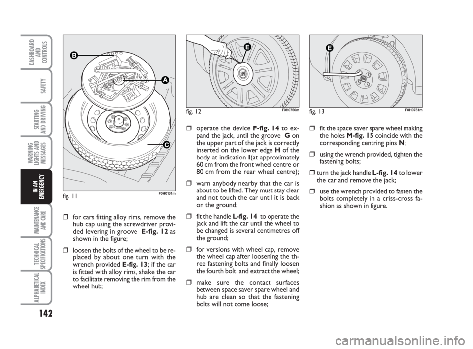
❒for cars fitting alloy rims, remove the
hub cap using the screwdriver provi-
ded levering in groove E-fig. 12as
shown in the figure;
❒loosen the bolts of the wheel to be re-
placed by about one turn with the
wrench provided E-fig. 13; if the car
is fitted with alloy rims, shake the car
to facilitate removing the rim from the
wheel hub;
fig. 12F0H0750m
❒operate the device F-fig. 14to ex-
pand the jack, until the groove Gon
the upper part of the jack is correctly
inserted on the lower edge Hof the
body at indication I(at approximately
60 cm from the front wheel centre or
80 cm from the rear wheel centre);
❒warn anybody nearby that the car is
about to be lifted. They must stay clear
and not touch the car until it is back
on the ground;
❒fit the handle L-fig. 14to operate the
jack and lift the car until the wheel to
be changed is several centimetres off
the ground;
❒for versions with wheel cap, remove
the wheel cap after loosening the th-
ree fastening bolts and finally loosen
the fourth bolt and extract the wheel;
❒make sure the contact surfaces
between space saver spare wheel and
hub are clean so that the fastening
bolts will not come loose;
fig. 13F0H0751m
❒fit the space saver spare wheel making
the holes M-fig. 15coincide with the
corresponding centring pins N;
❒using the wrench provided, tighten the
fastening bolts;
❒turn the jack handle L-fig. 14to lower
the car and remove the jack;
❒use the wrench provided to fasten the
bolts completely in a criss-cross fa-
shion as shown in figure.fig. 11F0H0161m
Page 145 of 210
144
STARTING
AND DRIVING
MAINTENANCE
AND CARE
TECHNICAL
SPECIFICATIONS
ALPHABETICAL
INDEX
DASHBOARD
AND
CONTROLS
SAFETY
WARNING
LIGHTS AND
MESSAGES
IN AN
EMERGENCY
WHEN NEEDING TO
CHANGE A BULB
GENERAL INSTRUCTIONS
❒When a bulb is not working, check
that the corresponding fuse is intact
before replacing it: refer to the “If a fu-
se blows” paragraph in this chapter for
fuse location.
❒before changing a bulb check the con-
tacts for oxidation;
❒Burnt bulbs must be replaced by
others of the same type and power.
❒Always check the height of the head-
light beam after changing a bulb. Versions with alloy rims
❒Check that the hub contact surfaces
are clean;
❒fit the normal wheel centring it on the
pins, lead in the fastening screws and
tighten them using the wrench provi-
ded;
❒lower the car and remove the jack;
❒using the wrench provided, fully tigh-
ten the bolts in the sequence shown
in fig. 16.
❒snap fit the wheel cup on the hub.
When you have finished
❒stow the spare wheel C-fig. 11 in the
space provided in the boot;
❒Fit the jack partially open in its box B-
fig. 11forcing it lightly to prevent it
from vibrating when travelling;
❒put the tools back into their places in
the container;
❒arrange the container and tools in the
spare wheel and secure the fastening
device A-fig. 11;
❒rearrange the preformed boot cover
correctly.
Modifications or repairs to
the electrical system (elec-
tronic control units) that are not car-
ried out properly or do not take the
technical specifications of the system
into account can cause malfunctions
leading to the risk of fire.
WARNING
Halogen bulbs contain pres-
surised gas which may cau-
se small fragments of glass to be
projected outwards if the bulb is
broken.
WARNING
Halogen lamps must be hand-
led holding the metallic part
only. Touching the transpa-
rent part of the bulb with
your fingers may reduce the intensity
of the emitted light and even compro-
mise duration of the lamp itself. In the
case of accidental contact, rub the
lamp with a cloth and spirit and leave
to dry.IMPORTANT A slight misting may appear
on the internal surface of the headlight:
this does not indicate a fault and is cau-
sed by low temperature and the degree of
humidity in the air. Misting will rapidly di-
sappear when the headlights are switched
on. The presence of drops inside the head-
lights indicates infiltration of water. Go to
a Fiat Dealership.
Page 146 of 210
145
STARTING
AND DRIVING
MAINTENANCE
AND CARE
TECHNICAL
SPECIFICATIONS
ALPHABETICAL
INDEX
DASHBOARD
AND
CONTROLS
SAFETY
WARNING
LIGHTS AND
MESSAGES
IN AN
EMERGENCY
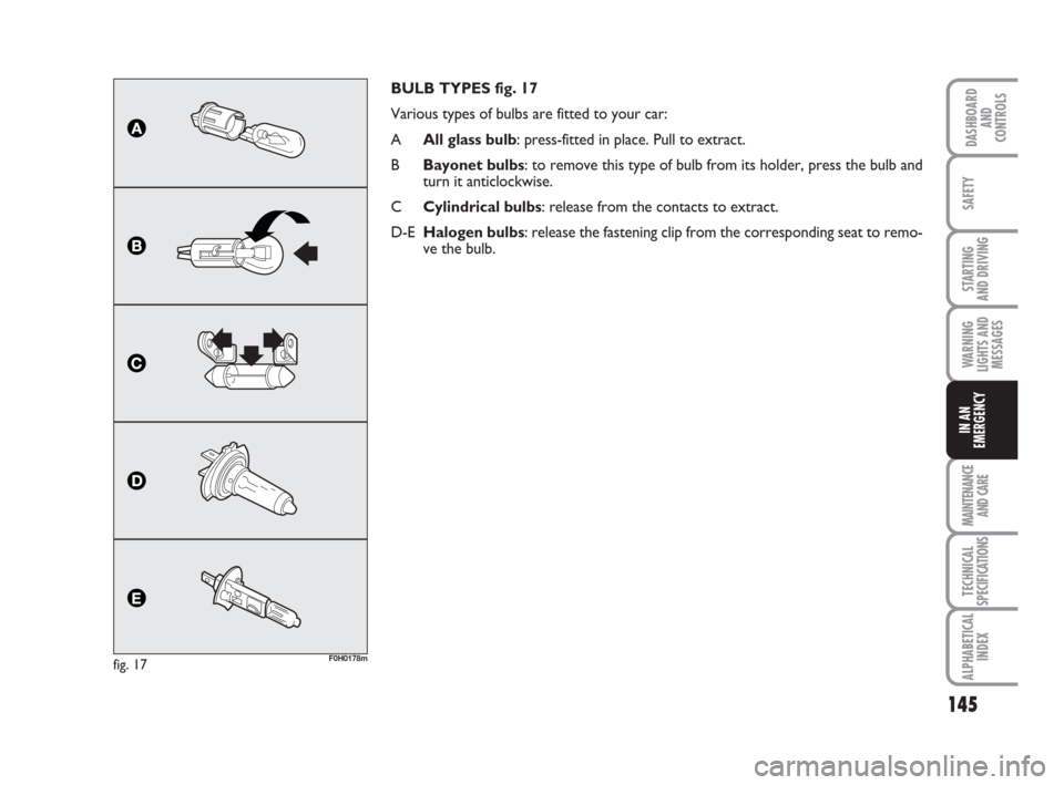
BULB TYPES fig. 17
Various types of bulbs are fitted to your car:
AAll glass bulb: press-fitted in place. Pull to extract.
BBayonet bulbs: to remove this type of bulb from its holder, press the bulb and
turn it anticlockwise.
CCylindrical bulbs: release from the contacts to extract.
D-EHalogen bulbs: release the fastening clip from the corresponding seat to remo-
ve the bulb.
fig. 17F0H0178m
Page 149 of 210
148
STARTING
AND DRIVING
MAINTENANCE
AND CARE
TECHNICAL
SPECIFICATIONS
ALPHABETICAL
INDEX
DASHBOARD
AND
CONTROLS
SAFETY
WARNING
LIGHTS AND
MESSAGES
IN AN
EMERGENCY
fig. 20F0H0181mfig. 21
C
B
D
F0H0214m
fig. 22F0H0182m
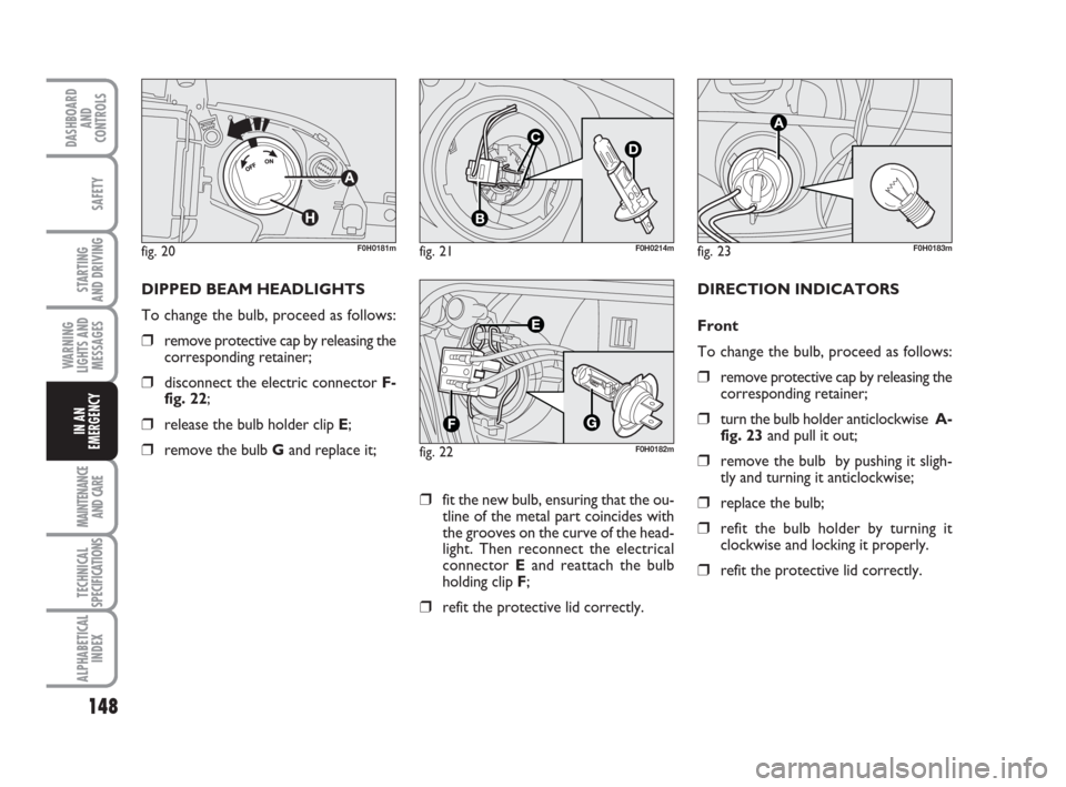
DIPPED BEAM HEADLIGHTS
To change the bulb, proceed as follows:
❒remove protective cap by releasing the
corresponding retainer;
❒disconnect the electric connector F-
fig. 22;
❒release the bulb holder clip E;
❒remove the bulb Gand replace it;
fig. 23F0H0183m
DIRECTION INDICATORS
Front
To change the bulb, proceed as follows:
❒remove protective cap by releasing the
corresponding retainer;
❒turn the bulb holder anticlockwise A-
fig. 23and pull it out;
❒remove the bulb by pushing it sligh-
tly and turning it anticlockwise;
❒replace the bulb;
❒refit the bulb holder by turning it
clockwise and locking it properly.
❒refit the protective lid correctly.
❒fit the new bulb, ensuring that the ou-
tline of the metal part coincides with
the grooves on the curve of the head-
light. Then reconnect the electrical
connector Eand reattach the bulb
holding clip F;
❒refit the protective lid correctly.
Page 150 of 210
149
STARTING
AND DRIVING
MAINTENANCE
AND CARE
TECHNICAL
SPECIFICATIONS
ALPHABETICAL
INDEX
DASHBOARD
AND
CONTROLS
SAFETY
WARNING
LIGHTS AND
MESSAGES
IN AN
EMERGENCY
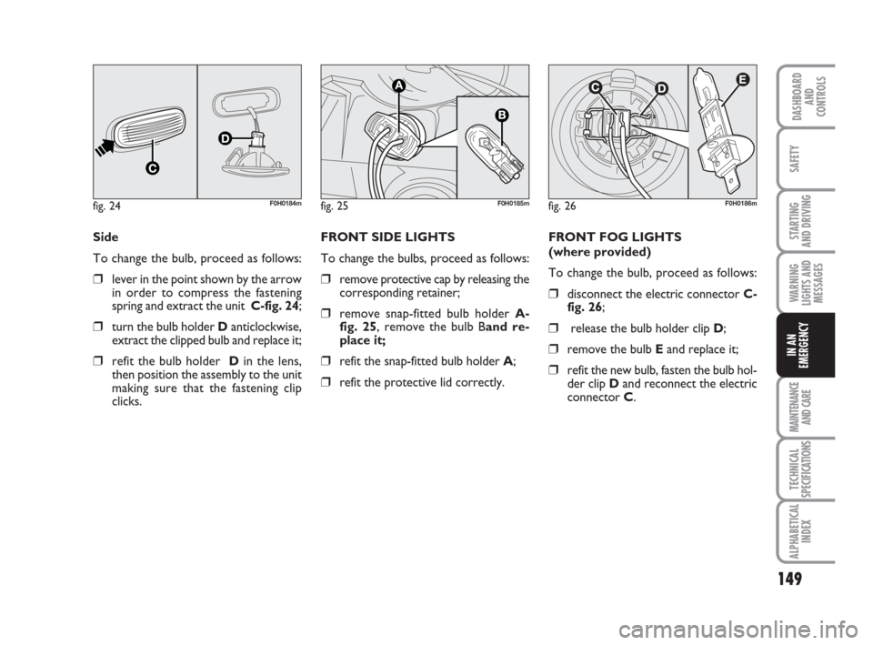
Side
To change the bulb, proceed as follows:
❒lever in the point shown by the arrow
in order to compress the fastening
spring and extract the unit C-fig. 24;
❒turn the bulb holder Danticlockwise,
extract the clipped bulb and replace it;
❒refit the bulb holder Din the lens,
then position the assembly to the unit
making sure that the fastening clip
clicks.
fig. 24F0H0184m
FRONT SIDE LIGHTS
To change the bulbs, proceed as follows:
❒remove protective cap by releasing the
corresponding retainer;
❒remove snap-fitted bulb holder A-
fig. 25, remove the bulb Band re-
place it;
❒refit the snap-fitted bulb holder A;
❒refit the protective lid correctly.FRONT FOG LIGHTS
(where provided)
To change the bulb, proceed as follows:
❒disconnect the electric connector C-
fig. 26;
❒release the bulb holder clip D;
❒remove the bulb Eand replace it;
❒refit the new bulb, fasten the bulb hol-
der clip Dand reconnect the electric
connector C.
fig. 25F0H0185mfig. 26F0H0186m
Page 154 of 210
153
STARTING
AND DRIVING
MAINTENANCE
AND CARE
TECHNICAL
SPECIFICATIONS
ALPHABETICAL
INDEX
DASHBOARD
AND
CONTROLS
SAFETY
WARNING
LIGHTS AND
MESSAGES
IN AN
EMERGENCY
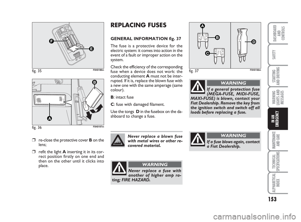
❒re-close the protective cover Bon the
lens;
❒refit the light Ainserting it in its cor-
rect position firstly on one end and
then on the other until it clicks into
place.
fig. 35F0H0196m
fig. 36F0H0197m
REPLACING FUSES
GENERAL INFORMATION fig. 37
The fuse is a protective device for the
electric system: it comes into action in the
event of a fault or improper action on the
system.
Check the efficiency of the corresponding
fuse when a device does not work: the
conducting element Amust not be inter-
rupted. If it is, replace the blown fuse with
a new one with the same amperage (same
colour).
B: intact fuse
C: fuse with damaged filament.
Use the tongs Din the fusebox on the da-
shboard to change a fuse.
fig. 37F0H0198m
Never replace a blown fuse
with metal wires or other re-
covered material.
Never replace a fuse with
another of higher amp ra-
ting; FIRE HAZARD.
WARNING
If a general protection fuse
(MEGA-FUSE, MIDI-FUSE,
MAXI-FUSE) is blown, contact your
Fiat Dealership. Remove the key from
the ignition switch and switch off all
loads before replacing a fuse.
WARNING
If a fuse blows again, contact
a Fiat Dealership.
WARNING