display FIAT IDEA 2009 1.G Owners Manual
[x] Cancel search | Manufacturer: FIAT, Model Year: 2009, Model line: IDEA, Model: FIAT IDEA 2009 1.GPages: 210, PDF Size: 3.62 MB
Page 5 of 210
4
SAFETY
STARTING
AND DRIVING
WARNING
LIGHTS AND
MESSAGES
IN AN
EMERGENCY
MANUTENZIONE
E CURA
TECHNICAL
SPECIFICATIONS
ALPHABETICAL
INDEX
DASHBOARD
AND CONTROLSDASHBOARD ...................................................................... 5
INSTRUMENT PANEL......................................................... 7
SYMBOLS ................................................................................ 9
THE FIAT CODE SYSTEM ................................................. 9
KEY KIT AND DOOR LOCKING SYSTEM ................. 10
IGNITION SWITCH ........................................................... 18
INSTRUMENTS .................................................................... 19
MULTIFUNCTIONAL DISPLAY ...................................... 20
RECONFIGURABLE MULTIFUNCTIONAL DISPLAY .. 23
ADJUSTING THE STEERING WHEEL ........................... 36
ADJUSTING THE SEATS ................................................... 36
HEADREST ............................................................................ 41
REAR VIEW MIRRORS ....................................................... 42
CLIMATE CONTROL SYSTEM ....................................... 44
HEATING AND VENTILATION SYSTEM .................... 45
MANUAL CLIMATE CONTROL SYSTEM ................... 48
AUTOMATIC TWO-ZONE CLIMATE CONTROL
SYSTEM .................................................................................. 51
EXTERNAL LIGHTS ........................................................... 58
WINDOW CLEANING ..................................................... 60
CRUISE CONTROL ............................................................ 63CEILING LIGHTS ................................................................. 64
HAZARD LIGHTS ................................................................ 66
FUEL CUT OFF SWITCH................................................... 67
INTERIOR EQUIPMENT ................................................... 68
SMOKER’S KIT ...................................................................... 71
SUN VISORS ......................................................................... 71
SUNROOF ............................................................................ 72
ELECTRIC WINDOWS ..................................................... 74
MANUAL REAR WINDOW WINDERS ........................ 75
BOOT ..................................................................................... 76
BONNET ............................................................................... 80
ROOF BARS .......................................................................... 81
HEADLIGHTS ....................................................................... 82
ABS SYSTEM ......................................................................... 83
EOBD SYSTEM ..................................................................... 84
GSI SYSTEM............................................................................ 84
CAR RADIO ......................................................................... 85
ACCESSORIES PURCHASED BY THE OWNER ........ 86
DUALDRIVE ELECTRIC POWER STEERING .............. 87
PARK SENSOR ..................................................................... 88
REFUELLING ........................................................................ 90
PROTECTING THE ENVIRONMENT ........................... 92
D D
A A
S S
H H
B B
O O
A A
R R
D D
A A
N N
D D
C C
O O
N N
T T
R R
O O
L L
S S
Page 8 of 210
7
SAFETY
STARTING
AND DRIVING
WARNING
LIGHTS AND
MESSAGES
IN AN
EMERGENCY
MAINTENANCE
AND CARE
TECHNICAL
SPECIFICATIONS
ALPHABETICAL
INDEX
DASHBOARD
AND CONTROLS
F0H0706m
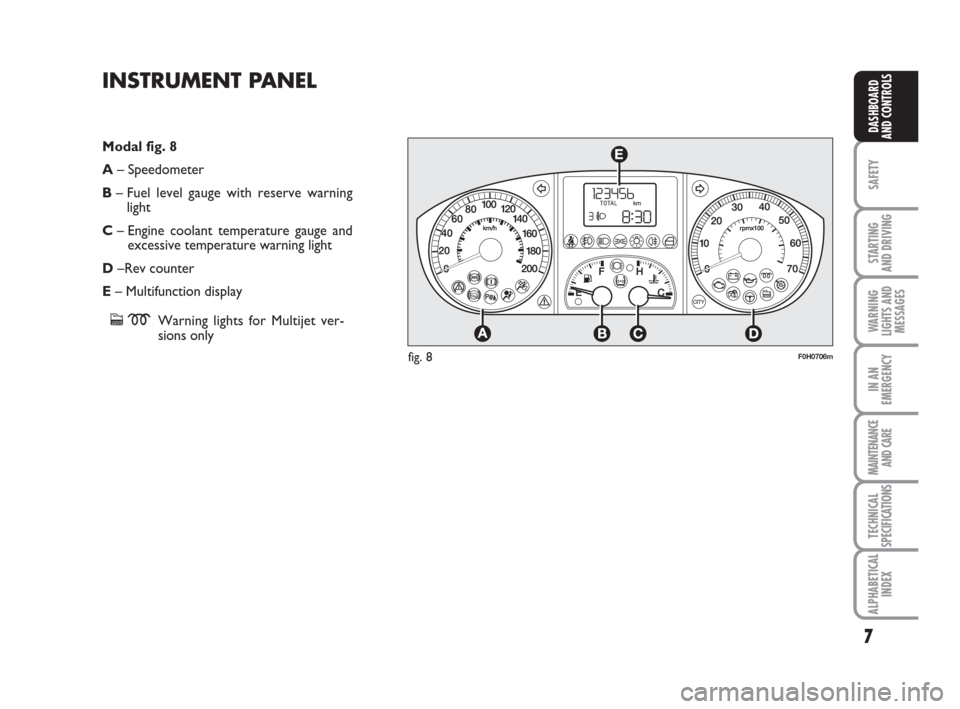
Modal fig. 8
A– Speedometer
B– Fuel level gauge with reserve warning
light
C– Engine coolant temperature gauge and
excessive temperature warning light
D–Rev counter
E– Multifunction display
cmWarning lights for Multijet ver-
sions only
INSTRUMENT PANEL
fig. 8
Page 9 of 210
8
SAFETY
STARTING
AND DRIVING
WARNING
LIGHTS AND
MESSAGES
IN AN
EMERGENCY
MAINTENANCE
AND CARE
TECHNICAL
SPECIFICATIONS
ALPHABETICAL
INDEX
DASHBOARD
AND CONTROLS
F0H0707m
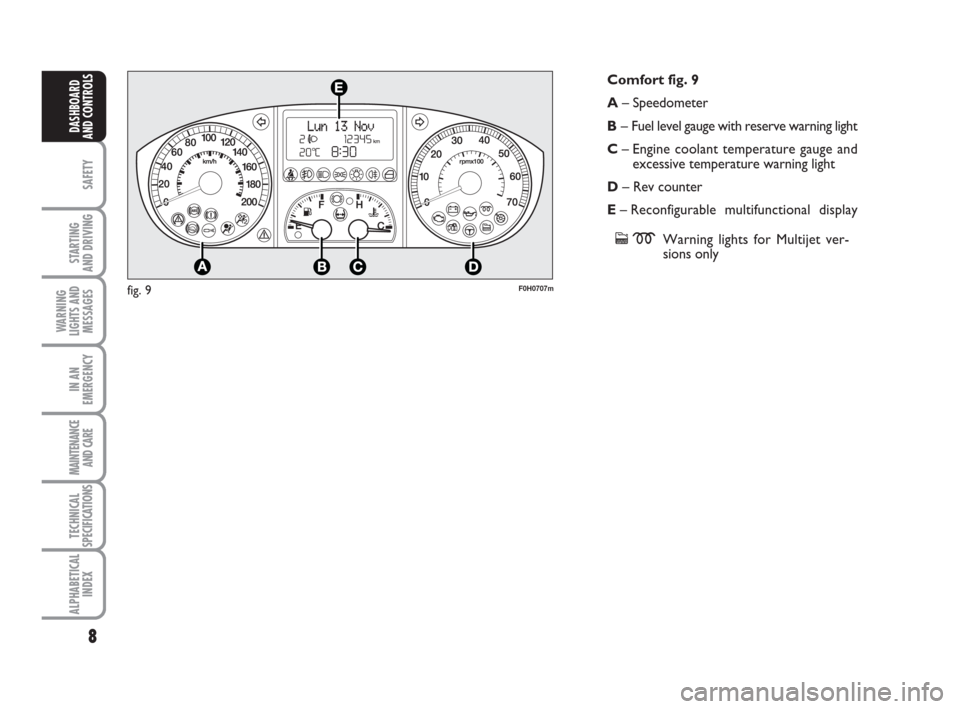
Comfort fig. 9
A– Speedometer
B– Fuel level gauge with reserve warning light
C– Engine coolant temperature gauge and
excessive temperature warning light
D– Rev counter
E– Reconfigurable multifunctional display
cmWarning lights for Multijet ver-
sions only
fig. 9
Page 11 of 210
10
SAFETY
STARTING
AND DRIVING
WARNING
LIGHTS AND
MESSAGES
IN AN
EMERGENCY
MAINTENANCE
AND CARE
TECHNICAL
SPECIFICATIONS
ALPHABETICAL
INDEX
DASHBOARD
AND CONTROLS
KEY KIT AND DOOR
LOCKING SYSTEM
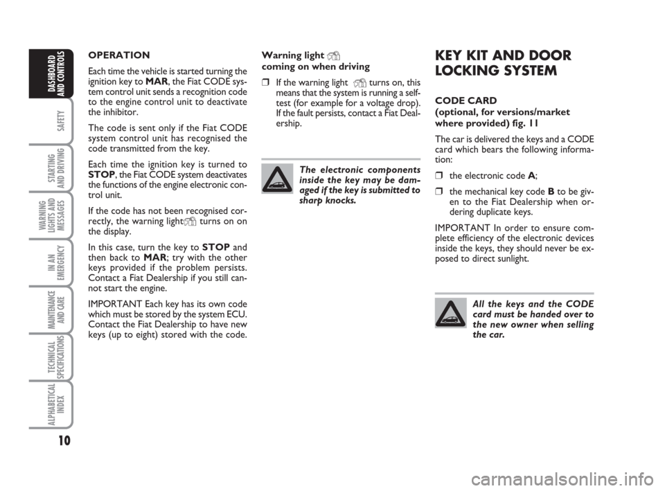
CODE CARD
(optional, for versions/market
where provided) fig. 11
The car is delivered the keys and a CODE
card which bears the following informa-
tion:
❒the electronic code A;
❒the mechanical key code Bto be giv-
en to the Fiat Dealership when or-
dering duplicate keys.
IMPORTANT In order to ensure com-
plete efficiency of the electronic devices
inside the keys, they should never be ex-
posed to direct sunlight. OPERATION
Each time the vehicle is started turning the
ignition key to MAR, the Fiat CODE sys-
tem control unit sends a recognition code
to the engine control unit to deactivate
the inhibitor.
The code is sent only if the Fiat CODE
system control unit has recognised the
code transmitted from the key.
Each time the ignition key is turned to
STOP, the Fiat CODE system deactivates
the functions of the engine electronic con-
trol unit.
If the code has not been recognised cor-
rectly, the warning light
Yturns on on
the display.
In this case, turn the key to STOPand
then back to MAR; try with the other
keys provided if the problem persists.
Contact a Fiat Dealership if you still can-
not start the engine.
IMPORTANT Each key has its own code
which must be stored by the system ECU.
Contact the Fiat Dealership to have new
keys (up to eight) stored with the code.Warning light
Ycoming on when driving
❒If the warning light Yturns on, this
means that the system is running a self-
test (for example for a voltage drop).
If the fault persists, contact a Fiat Deal-
ership.
The electronic components
inside the key may be dam-
aged if the key is submitted to
sharp knocks.
All the keys and the CODE
card must be handed over to
the new owner when selling
the car.
Page 21 of 210
20
SAFETY
STARTING
AND DRIVING
WARNING
LIGHTS AND
MESSAGES
IN AN
EMERGENCY
MAINTENANCE
AND CARE
TECHNICAL
SPECIFICATIONS
ALPHABETICAL
INDEX
DASHBOARD
AND CONTROLS
This shows the temperature of the engine
coolant fluid and starts working when the
fluid temperature exceeds approx. 50°C
circa. In normal conditions, the needle may
point to different positions according to
use and the engine cooling system man-
agement.
IMPORTANT The needle will point to the
lowest value of the scale (low tempera-
ture) and warning light Awill light up to
indicate a fault in the system. Go to a Fi-
at Dealership to have the system checked.
If the needle reaches the red
area, stop the engine imme-
diately and contact a Fiat
Dealership.MULTIFUNCTIONAL
DISPLAY
(on two-line
modal panel)
The car can be equipped with the multi-
function display for showing useful infor-
mation necessary when driving according
to settings.
fig. 26F0H0782m
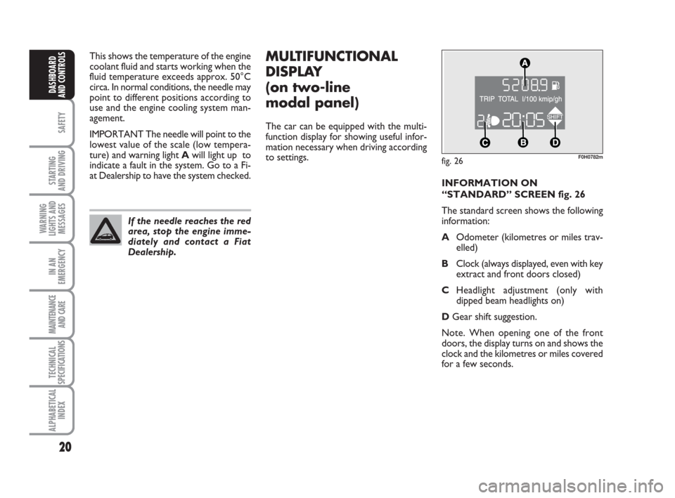
INFORMATION ON
“STANDARD” SCREEN fig. 26
The standard screen shows the following
information:
AOdometer (kilometres or miles trav-
elled)
BClock (always displayed, even with key
extract and front doors closed)
CHeadlight adjustment (only with
dipped beam headlights on)
DGear shift suggestion.
Note. When opening one of the front
doors, the display turns on and shows the
clock and the kilometres or miles covered
for a few seconds.
Page 22 of 210
21
SAFETY
STARTING
AND DRIVING
WARNING
LIGHTS AND
MESSAGES
IN AN
EMERGENCY
MAINTENANCE
AND CARE
TECHNICAL
SPECIFICATIONS
ALPHABETICAL
INDEX
DASHBOARD
AND CONTROLS
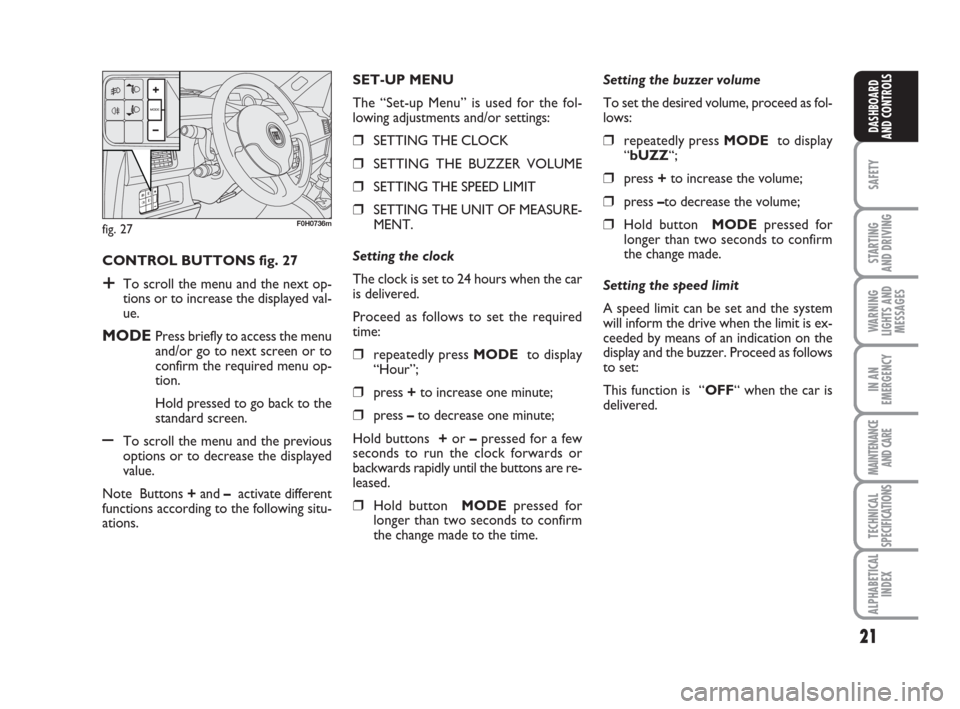
CONTROL BUTTONS fig. 27
+To scroll the menu and the next op-
tions or to increase the displayed val-
ue.
MODEPress briefly to access the menu
and/or go to next screen or to
confirm the required menu op-
tion.
Hold pressed to go back to the
standard screen.
–To scroll the menu and the previous
options or to decrease the displayed
value.
Note Buttons +and –activate different
functions according to the following situ-
ations.Setting the buzzer volume
To set the desired volume, proceed as fol-
lows:
❒repeatedly press MODE to display
“bUZZ“;
❒press +to increase the volume;
❒press –to decrease the volume;
❒Hold button MODEpressed for
longer than two seconds to confirm
the change made.
Setting the speed limit
A speed limit can be set and the system
will inform the drive when the limit is ex-
ceeded by means of an indication on the
display and the buzzer. Proceed as follows
to set:
This function is “OFF“ when the car is
delivered. SET-UP MENU
The “Set-up Menu” is used for the fol-
lowing adjustments and/or settings:
❒SETTING THE CLOCK
❒SETTING THE BUZZER VOLUME
❒SETTING THE SPEED LIMIT
❒SETTING THE UNIT OF MEASURE-
MENT.
Setting the clock
The clock is set to 24 hours when the car
is delivered.
Proceed as follows to set the required
time:
❒repeatedly press MODE to display
“Hour”;
❒press +to increase one minute;
❒press –to decrease one minute;
Hold buttons +or –pressed for a few
seconds to run the clock forwards or
backwards rapidly until the buttons are re-
leased.
❒Hold button MODEpressed for
longer than two seconds to confirm
the change made to the time.
fig. 27F0H0736m
Page 23 of 210
22
SAFETY
STARTING
AND DRIVING
WARNING
LIGHTS AND
MESSAGES
IN AN
EMERGENCY
MAINTENANCE
AND CARE
TECHNICAL
SPECIFICATIONS
ALPHABETICAL
INDEX
DASHBOARD
AND CONTROLS
Setting the unit of measurement
Proceed as follows to set the required unit
of measurement (kilometres or miles):
❒repeatedly press MODE to dis-
play“Unit”;
❒press button + or – to change the unit
of measurement;
❒to confirm the setting, hold button
MODEpressed for longer than two
seconds.
Fuel inertia
switch tripped indication
The indication appears automatically if the
fuel inertia switch trips follow a collision
of considerable severity.
The switch cuts off fuel feed.
See the “Fuel inertia switch” chapter for
more information. Proceed as follows to select:
❒repeatedly press MODE to display
“SPEEd“;
❒press + to increase the value corre-
sponding to speed (the maximum lim-
it is 250 km/h);
❒press – to decrease the value corre-
sponding to speed (the limit is 30
km/h under which it switches to
“OFF”);
❒to confirm the setting, hold button
MODEpressed for longer than two
seconds.
If after the “FPSon” message
appears, you smell fuel or
see leaks from the fuel system, do not
reset the switch to avoid fine risk.
WARNING
Page 24 of 210
23
SAFETY
STARTING
AND DRIVING
WARNING
LIGHTS AND
MESSAGES
IN AN
EMERGENCY
MAINTENANCE
AND CARE
TECHNICAL
SPECIFICATIONS
ALPHABETICAL
INDEX
DASHBOARD
AND CONTROLS
fig. 28F0H0781m
MULTIFUNCTIONAL
DISPLAY
(on three-line comfort
panel)
The car can be equipped with the multi-
function display for showing useful infor-
mation necessary when driving according
to settings.
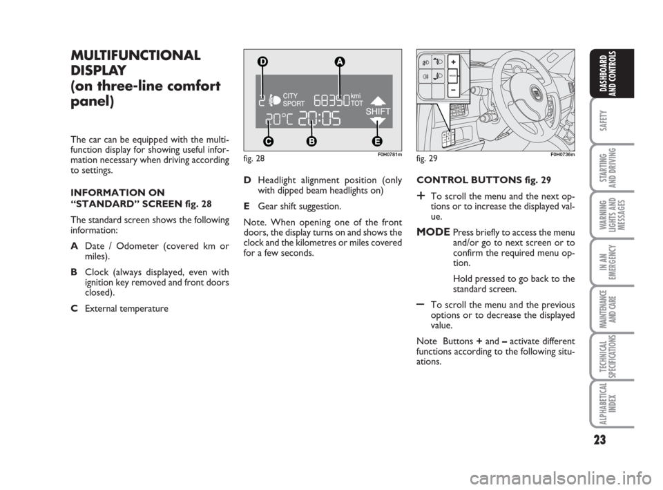
INFORMATION ON
“STANDARD” SCREEN fig. 28
The standard screen shows the following
information:
ADate / Odometer (covered km or
miles).
BClock (always displayed, even with
ignition key removed and front doors
closed).
CExternal temperature CONTROL BUTTONS fig. 29
+To scroll the menu and the next op-
tions or to increase the displayed val-
ue.
MODEPress briefly to access the menu
and/or go to next screen or to
confirm the required menu op-
tion.
Hold pressed to go back to the
standard screen.
–To scroll the menu and the previous
options or to decrease the displayed
value.
Note Buttons +and –activate different
functions according to the following situ-
ations. DHeadlight alignment position (only
with dipped beam headlights on)
EGear shift suggestion.
Note. When opening one of the front
doors, the display turns on and shows the
clock and the kilometres or miles covered
for a few seconds.
fig. 29F0H0736m
Page 25 of 210
24
SAFETY
STARTING
AND DRIVING
WARNING
LIGHTS AND
MESSAGES
IN AN
EMERGENCY
MAINTENANCE
AND CARE
TECHNICAL
SPECIFICATIONS
ALPHABETICAL
INDEX
DASHBOARD
AND CONTROLS
Headlight adjustment (only
with dipped beam headlights on)
– when the standard page is displayed, this
is used to adjust the headlights (see the
“Headlights” paragraph in this chapter).
Setup menu
– for scrolling the menu up and down;
– to increase or decrease values during
settings.
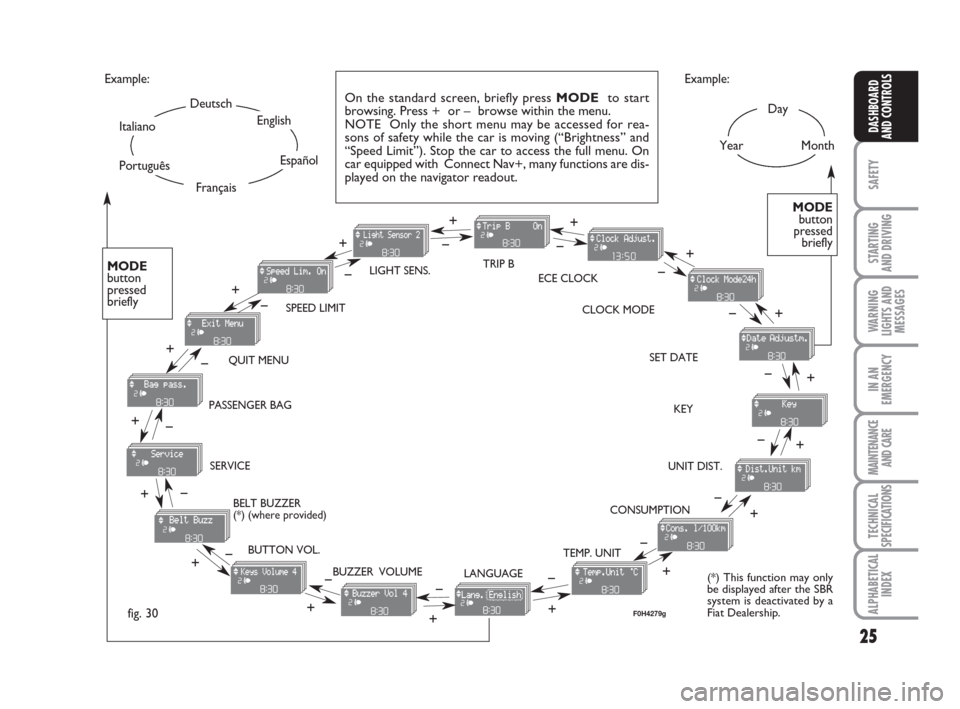
SETUP MENU Fig. 30
The menu comprises a series of functions
arranged in a “circular fashion” which can
be selected through buttons +and –to
access the different select operations and
settings (setup) given in the following para-
graphs.
The setup menu is activated by pressing
briefly button MODE.
Single presses on buttons +and –will
scroll the setup menu options.
Management modes differ with each oth-
er according to the characteristic of the
option selected.Selecting “Set Date” and “Set time”:
– briefly press button MODEto select
the first value to be changed (e.g. hours
/minutes or year / month / day).
– press buttons +and –(by single press-
es) to select the new setting;
– briefly press button MODEto store the
new setting and go to the next setup menu
option: if this is the last one you will go
back to the previously selected option of
the main menu.
Prolonged pressing of the button
MODE make it possible:
– quit set-up and to save only the changes
stored by the user (and confirmed by
pressing button MODE).
The setup menu environment is timed.
Only the changes saved by the user by
briefly pressing MODE) will be saved
when the menu is automatically closed. NOTE Only the following functions can
be adjusted/set on the instrument panel
display if the Connect Nav+ system is pre-
sent: “Lights”, “Speed limit”, “Light sen-
sor” (where provided), “Belt buzzer” and
“Passenger airbag”. The other functions
are shown on the Connect Nav+ system
display. Set and adjustment them there.
Selecting a menu option
– briefly press button MODEto select
the menu option that needs to be
changed.
– press buttons +and –(by single press-
es) to select the new setting;
– briefly press button MODEto store
the new setting and at the same time go
back to the previously selected menu op-
tion.
Page 26 of 210
25
SAFETY
STARTING
AND DRIVING
WARNING
LIGHTS AND
MESSAGES
IN AN
EMERGENCY
MAINTENANCE
AND CARE
TECHNICAL
SPECIFICATIONS
ALPHABETICAL
INDEX
DASHBOARD
AND CONTROLS
Day
YearMonth Example:
CONSUMPTION QUIT MENUSPEED LIMITTRIP B
LIGHT SENS.
CLOCK MODE ECE CLOCK
SET DATE
KEY
UNIT DIST.
BUTTON VOL.
BUZZER VOLUME SERVICE
LANGUAGE TEMP. UNIT
Example:
– +
+– – –
+ +
–
–
+
+++
–––
+ +
–
MODE
button
pressed
briefly
On the standard screen, briefly press MODEto start
browsing. Press + or – browse within the menu.
NOTE Only the short menu may be accessed for rea-
sons of safety while the car is moving (“Brightness” and
“Speed Limit”). Stop the car to access the full menu. On
car equipped with Connect Nav+, many functions are dis-
played on the navigator readout.
–
+ +
–
MODE
button
pressed
briefly
Deutsch
English
Español
Italiano
Português
Français
(*) This function may only
be displayed after the SBR
system is deactivated by a
Fiat Dealership.
fig. 30
+
– +
–+
–
+
–
+ –
BELT BUZZER
(*) (where provided) PASSENGER BAG
F0H4279g