FIAT IDEA 2010 1.G Service Manual
Manufacturer: FIAT, Model Year: 2010, Model line: IDEA, Model: FIAT IDEA 2010 1.GPages: 210, PDF Size: 4.4 MB
Page 41 of 210
40
SAFETY
STARTING
AND DRIVING
WARNING
LIGHTS AND
MESSAGES
IN AN
EMERGENCY
MAINTENANCE
AND CARE
TECHNICAL
SPECIFICATIONS
ALPHABETICAL
INDEX
DASHBOARD
AND CONTROLS
For maximum safety, keep
the back of your seat up-
right, lean back into it and make sure
the seat belt fits closely across your
hips.
WARNING
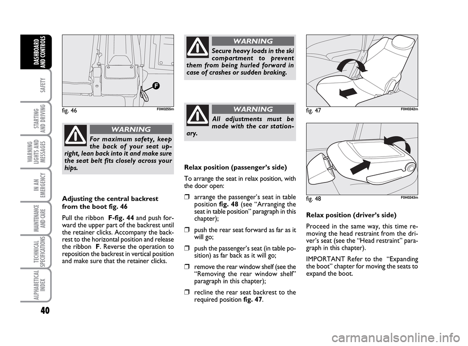
Adjusting the central backrest
from the boot fig. 46
Pull the ribbon F-fig. 44and push for-
ward the upper part of the backrest until
the retainer clicks. Accompany the back-
rest to the horizontal position and release
the ribbon F. Reverse the operation to
reposition the backrest in vertical position
and make sure that the retainer clicks.
Secure heavy loads in the ski
compartment to prevent
them from being hurled forward in
case of crashes or sudden braking.
WARNING
All adjustments must be
made with the car station-
ary.
WARNINGfig. 46F0H0255m
Relax position (passenger’s side)
To arrange the seat in relax position, with
the door open:
❒arrange the passenger’s seat in table
position fig. 48(see “Arranging the
seat in table position” paragraph in this
chapter);
❒push the rear seat forward as far as it
will go;
❒push the passenger’s seat (in table po-
sition) as far back as it will go;
❒remove the rear window shelf (see the
“Removing the rear window shelf”
paragraph in this chapter);
❒recline the rear seat backrest to the
required position fig. 47.Relax position (driver’s side)
Proceed in the same way, this time re-
moving the head restraint from the dri-
ver’s seat (see the “Head restraint” para-
graph in this chapter).
IMPORTANT Refer to the “Expanding
the boot” chapter for moving the seats to
expand the boot.
fig. 47F0H0242m
fig. 48F0H0243m
036-092 LUM IDEA GB 2 ed.qxd 14-01-2010 12:14 Pagina 40
Page 42 of 210
41
SAFETY
STARTING
AND DRIVING
WARNING
LIGHTS AND
MESSAGES
IN AN
EMERGENCY
MAINTENANCE
AND CARE
TECHNICAL
SPECIFICATIONS
ALPHABETICAL
INDEX
DASHBOARD
AND CONTROLS
HEADREST
FRONT
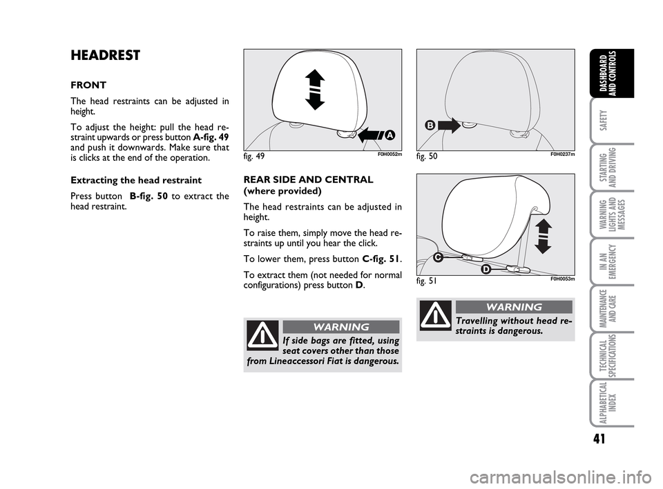
The head restraints can be adjusted in
height.
To adjust the height: pull the head re-
straint upwards or press button A-fig. 49
and push it downwards. Make sure that
is clicks at the end of the operation.
Extracting the head restraint
Press button B-fig. 50to extract the
head restraint.
fig. 49F0H0052mfig. 50F0H0237m
fig. 51F0H0053m
REAR SIDE AND CENTRAL
(where provided)
The head restraints can be adjusted in
height.
To raise them, simply move the head re-
straints up until you hear the click.
To lower them, press button C-fig. 51.
To extract them (not needed for normal
configurations) press button D.
If side bags are fitted, using
seat covers other than those
from Lineaccessori Fiat is dangerous.
WARNINGTravelling without head re-
straints is dangerous.
WARNING
036-092 LUM IDEA GB 2 ed.qxd 14-01-2010 12:14 Pagina 41
Page 43 of 210
42
SAFETY
STARTING
AND DRIVING
WARNING
LIGHTS AND
MESSAGES
IN AN
EMERGENCY
MAINTENANCE
AND CARE
TECHNICAL
SPECIFICATIONS
ALPHABETICAL
INDEX
DASHBOARD
AND CONTROLS
The head restraints must be
adjusted so that they sup-
port your head and not your neck.
Only in this way may they perform
their protective action.
WARNING
To optimise head restraint
protective action, adjust the
seat back upright and keep your head
as close as possible to the head re-
straint.
WARNING
To refit the head restraint,
arrange it the right way and
then proceed as for checking that it
is locked.
WARNING
Saddle-shaped rear head re-
straints optimise visibility
and must always be raised it when an
occupant is present.
WARNING
REAR VIEW MIRRORS
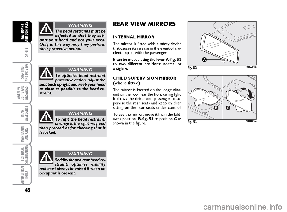
INTERNAL MIRROR
The mirror is fitted with a safety device
that causes its release in the event of a vi-
olent impact with the passenger.
It can be moved using the lever A-fig. 52
to two different positions: normal or
antiglare.
CHILD SUPERVISION MIRROR
(where fitted)
The mirror is located on the longitudinal
unit on the roof near the front ceiling light.
It allows the driver and passenger to su-
pervise the rear seats and keep children
sitting on the rear seats under control.
To use the mirror, move it from the fold-
away position B-fig. 53to position Cas
shown in the figure.
fig. 52F0H0056m
fig. 53F0H0057m
036-092 LUM IDEA GB 2 ed.qxd 14-01-2010 12:14 Pagina 42
Page 44 of 210
43
SAFETY
STARTING
AND DRIVING
WARNING
LIGHTS AND
MESSAGES
IN AN
EMERGENCY
MAINTENANCE
AND CARE
TECHNICAL
SPECIFICATIONS
ALPHABETICAL
INDEX
DASHBOARD
AND CONTROLS
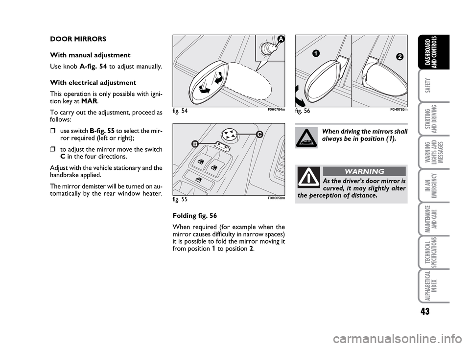
DOOR MIRRORS
With manual adjustment
Use knob A-fig. 54to adjust manually.
With electrical adjustment
This operation is only possible with igni-
tion key at MAR.
To carry out the adjustment, proceed as
follows:
❒use switch B-fig. 55to select the mir-
ror required (left or right);
❒to adjust the mirror move the switch
Cin the four directions.
Adjust with the vehicle stationary and the
handbrake applied.
The mirror demister will be turned on au-
tomatically by the rear window heater.
fig. 55F0H0058m
Folding fig. 56
When required (for example when the
mirror causes difficulty in narrow spaces)
it is possible to fold the mirror moving it
from position 1 to position 2.When driving the mirrors shall
always be in position (
1).
As the driver’s door mirror is
curved, it may slightly alter
the perception of distance.
WARNING
fig. 54F0H0784mfig. 56F0H0785m
036-092 LUM IDEA GB 2 ed.qxd 14-01-2010 12:14 Pagina 43
Page 45 of 210
44
SAFETY
STARTING
AND DRIVING
WARNING
LIGHTS AND
MESSAGES
IN AN
EMERGENCY
MAINTENANCE
AND CARE
TECHNICAL
SPECIFICATIONS
ALPHABETICAL
INDEX
DASHBOARD
AND CONTROLS
HEATING/CLIMATE CONTROL SYSTEM
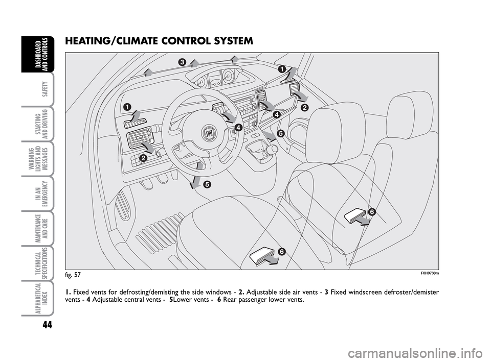
1.Fixed vents for defrosting/demisting the side windows - 2.Adjustable side air vents - 3Fixed windscreen defroster/demister
vents - 4Adjustable central vents - 5Lower vents - 6Rear passenger lower vents.
F0H0738mfig. 57
036-092 LUM IDEA GB 2 ed.qxd 14-01-2010 12:14 Pagina 44
Page 46 of 210
45
SAFETY
STARTING
AND DRIVING
WARNING
LIGHTS AND
MESSAGES
IN AN
EMERGENCY
MAINTENANCE
AND CARE
TECHNICAL
SPECIFICATIONS
ALPHABETICAL
INDEX
DASHBOARD
AND CONTROLS
fig. 58F0H0061m
fig. 59F0H0062m
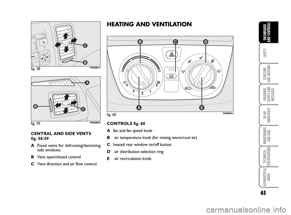
CENTRAL AND SIDE VENTS
fig. 58-59
AFixed vents for defrosting/demisting
side windows.
BVent open/closed control
CVent direction and air flow control
F0H0063m
HEATING AND VENTILATION
CONTROLS fig. 60
Afan and fan speed knob
Bair temperature knob (for mixing warm/cool air)
Cheated rear window on/off button
Dair distribution selection ring
Eair recirculation knob.
fig. 60
036-092 LUM IDEA GB 2 ed.qxd 14-01-2010 12:14 Pagina 45
Page 47 of 210
46
SAFETY
STARTING
AND DRIVING
WARNING
LIGHTS AND
MESSAGES
IN AN
EMERGENCY
MAINTENANCE
AND CARE
TECHNICAL
SPECIFICATIONS
ALPHABETICAL
INDEX
DASHBOARD
AND CONTROLS
AIR DISTRIBUTION
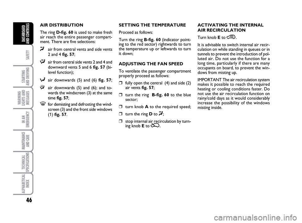
The ring D-fig. 60is used to make fresh
air reach the entire passenger compart-
ment. There are five selections:
«air from central vents and side vents
2 and 4 fig. 57;
∆air from central side vents 2 and 4 and
downward vents 5 and 6 fig. 57 (bi-
level function);
≈air downwards (5) and (6) fig. 57;
ƒair downwards (5) and (6); and to-
wards the windscreen (3) at the same
time fig. 57;
-for demisting and defrosting the wind-
screen (3) and the front side windows
(1) fig. 57.SETTING THE TEMPERATURE
Proceed as follows:
Turn the ring B-fig. 60(indicator point-
ing to the red sector) rightwards to turn
the temperature up or leftwards to turn
it down;
ADJUSTING THE FAN SPEED
To ventilate the passenger compartment
properly proceed as follows:
❒fully open the central (4) and side (2)
air vents fig. 57;
❒turn the ring B-fig. 60to the blue
sector;
❒turn knob Ato the required speed;
❒turn the ring Dto «;
❒stop internal air recirculation by turn-
ing knob E to Ú.ACTIVATING THE INTERNAL
AIR RECIRCULATION
Turn knob Eto
….
It is advisable to switch internal air recir-
culation on while standing in queues or in
tunnels to prevent the introduction of pol-
luted air. Do not use the function for a
long time, particularly if there are many
occupants on board, to prevent the win-
dows from misting up.
IMPORTANT The air recirculation system
makes it possible to reach the required
heating or cooling conditions faster. Do
not use the air recirculation function on
rainy/cold days as it would considerably
increase the possibility of the windows
misting inside.
036-092 LUM IDEA GB 2 ed.qxd 14-01-2010 12:14 Pagina 46
Page 48 of 210
47
SAFETY
STARTING
AND DRIVING
WARNING
LIGHTS AND
MESSAGES
IN AN
EMERGENCY
MAINTENANCE
AND CARE
TECHNICAL
SPECIFICATIONS
ALPHABETICAL
INDEX
DASHBOARD
AND CONTROLS
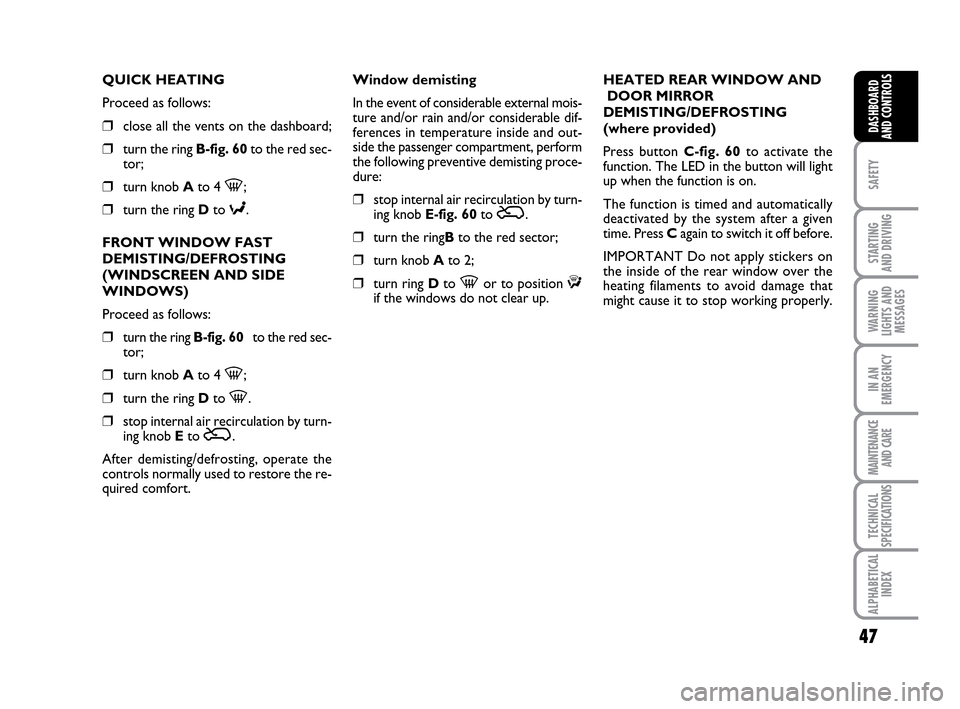
QUICK HEATING
Proceed as follows:
❒close all the vents on the dashboard;
❒turn the ringB-fig. 60to the red sec-
tor;
❒turn knob Ato 4 -;
❒turn the ring Dto ≈.
FRONT WINDOW FAST
DEMISTING/DEFROSTING
(WINDSCREEN AND SIDE
WINDOWS)
Proceed as follows:
❒turn the ringB-fig. 60to the red sec-
tor;
❒turn knob Ato 4 -;
❒turn the ring Dto -.
❒stop internal air recirculation by turn-
ing knob Eto Ú.
After demisting/defrosting, operate the
controls normally used to restore the re-
quired comfort.Window demisting
In the event of considerable external mois-
ture and/or rain and/or considerable dif-
ferences in temperature inside and out-
side the passenger compartment, perform
the following preventive demisting proce-
dure:
❒stop internal air recirculation by turn-
ing knob E-fig. 60to Ú.
❒turn the ringBto the red sector;
❒turn knob Ato 2;
❒turn ring Dto -or to position ƒif the windows do not clear up. HEATED REAR WINDOW AND
DOOR MIRROR
DEMISTING/DEFROSTING
(where provided)
Press button C-fig. 60to activate the
function. The LED in the button will light
up when the function is on.
The function is timed and automatically
deactivated by the system after a given
time. Press Cagain to switch it off before.
IMPORTANT Do not apply stickers on
the inside of the rear window over the
heating filaments to avoid damage that
might cause it to stop working properly.
036-092 LUM IDEA GB 2 ed.qxd 14-01-2010 12:14 Pagina 47
Page 49 of 210
48
SAFETY
STARTING
AND DRIVING
WARNING
LIGHTS AND
MESSAGES
IN AN
EMERGENCY
MAINTENANCE
AND CARE
TECHNICAL
SPECIFICATIONS
ALPHABETICAL
INDEX
DASHBOARD
AND CONTROLS
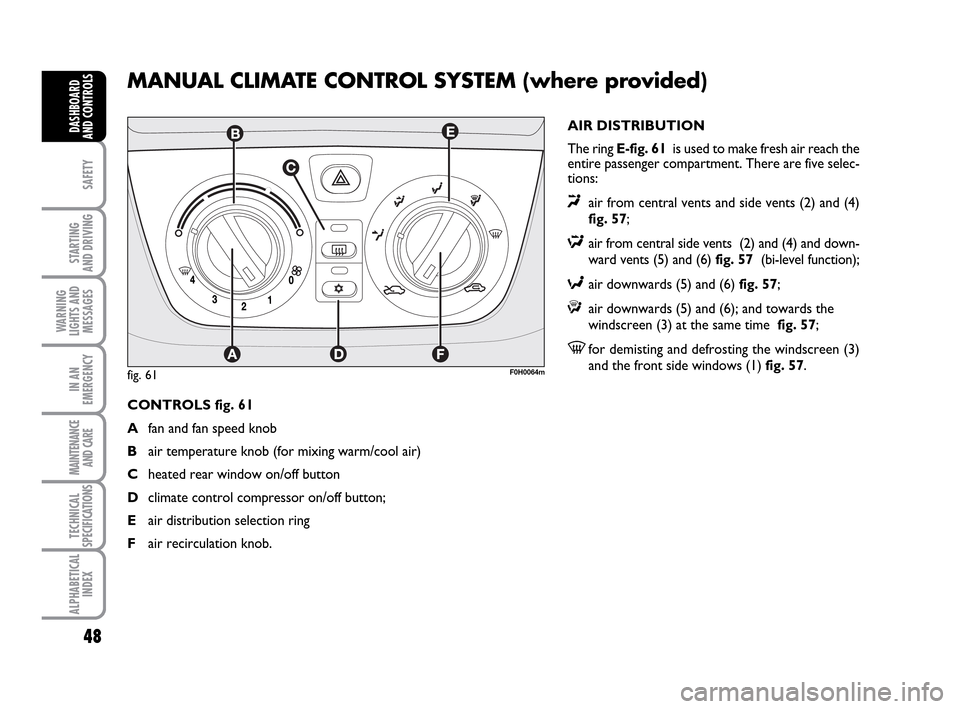
MANUAL CLIMATE CONTROL SYSTEM (where provided)
AIR DISTRIBUTION
The ring E-fig. 61is used to make fresh air reach the
entire passenger compartment. There are five selec-
tions:
«air from central vents and side vents (2) and (4)
fig. 57;
∆air from central side vents (2) and (4) and down-
ward vents (5) and (6) fig. 57 (bi-level function);
≈air downwards (5) and (6) fig. 57;
ƒair downwards (5) and (6); and towards the
windscreen (3) at the same time fig. 57;
-for demisting and defrosting the windscreen (3)
and the front side windows (1) fig. 57.
CONTROLS fig. 61
Afan and fan speed knob
Bair temperature knob (for mixing warm/cool air)
Cheated rear window on/off button
Dclimate control compressor on/off button;
Eair distribution selection ring
Fair recirculation knob.
F0H0064mfig. 61
036-092 LUM IDEA GB 2 ed.qxd 14-01-2010 12:14 Pagina 48
Page 50 of 210
49
SAFETY
STARTING
AND DRIVING
WARNING
LIGHTS AND
MESSAGES
IN AN
EMERGENCY
MAINTENANCE
AND CARE
TECHNICAL
SPECIFICATIONS
ALPHABETICAL
INDEX
DASHBOARD
AND CONTROLS
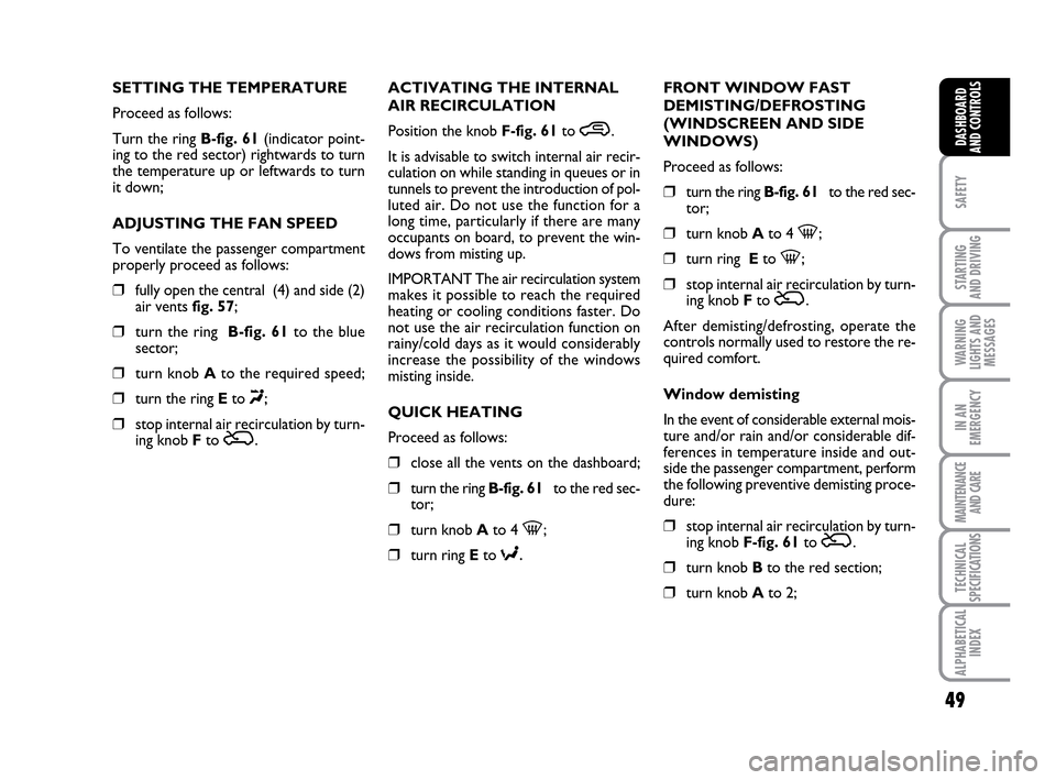
SETTING THE TEMPERATURE
Proceed as follows:
Turn the ring B-fig. 61(indicator point-
ing to the red sector) rightwards to turn
the temperature up or leftwards to turn
it down;
ADJUSTING THE FAN SPEED
To ventilate the passenger compartment
properly proceed as follows:
❒fully open the central (4) and side (2)
air vents fig. 57;
❒turn the ring B-fig. 61to the blue
sector;
❒turn knob Ato the required speed;
❒turn the ring Eto «;
❒stop internal air recirculation by turn-
ing knob Fto Ú.ACTIVATING THE INTERNAL
AIR RECIRCULATION
Position the knob F-fig. 61to
….
It is advisable to switch internal air recir-
culation on while standing in queues or in
tunnels to prevent the introduction of pol-
luted air. Do not use the function for a
long time, particularly if there are many
occupants on board, to prevent the win-
dows from misting up.
IMPORTANT The air recirculation system
makes it possible to reach the required
heating or cooling conditions faster. Do
not use the air recirculation function on
rainy/cold days as it would considerably
increase the possibility of the windows
misting inside.
QUICK HEATING
Proceed as follows:
❒close all the vents on the dashboard;
❒turn the ring B-fig. 61to the red sec-
tor;
❒turn knob Ato 4 -;
❒turn ring Eto ≈.
FRONT WINDOW FAST
DEMISTING/DEFROSTING
(WINDSCREEN AND SIDE
WINDOWS)
Proceed as follows:
❒turn the ring B-fig. 61to the red sec-
tor;
❒turn knob Ato 4 -;
❒turn ring Eto -;
❒stop internal air recirculation by turn-
ing knob Fto Ú.
After demisting/defrosting, operate the
controls normally used to restore the re-
quired comfort.
Window demisting
In the event of considerable external mois-
ture and/or rain and/or considerable dif-
ferences in temperature inside and out-
side the passenger compartment, perform
the following preventive demisting proce-
dure:
❒stop internal air recirculation by turn-
ing knob F-fig. 61to Ú.
❒turn knob Bto the red section;
❒turn knob Ato 2;
036-092 LUM IDEA GB 2 ed.qxd 14-01-2010 12:14 Pagina 49