sensor FIAT IDEA 2012 1.G Owners Manual
[x] Cancel search | Manufacturer: FIAT, Model Year: 2012, Model line: IDEA, Model: FIAT IDEA 2012 1.GPages: 210, PDF Size: 3.65 MB
Page 5 of 210
4
SAFETY
DEVICES
CORRECT USE
OF THE CAR
WARNING
LIGHTS AND
MESSAGES
IN AN
EMERGENCY
CAR
MAINTENANCE
TECHNICAL
SPECIFICATIONS
INDEX
DASHBOARD
AND CONTROLSDASHBOARD........................................................................ 5
INSTRUMENT PANEL ....................................................... 7
SYMBOLS ............................................................................... 9
THE FIAT CODE SYSTEM ................................................. 9
KEY KIT AND DOOR LOCKING .................................. 10
IGNITION SWITCH ............................................................ 18
INSTRUMENTS ..................................................................... 19
MULTIFUNCTION DISPLAY ........................................... 20
RECONFIGURABLE MULTIFUNCTION DISPLAY ... 23
ADJUSTMENT OF THE WHEEL ...................................... 36
ADJUSTMENT OF THE SEATS ......................................... 36
HEAD RESTRAINTS ............................................................ 41
REARVIEW MIRRORS ......................................................... 42
HEATING/CLIMATE
CONTROL SYSTEM ........................................................... 44
HEATING AND VENTILATION ...................................... 45
MANUAL CLIMATE CONTROL SYSTEM ................... 48
AUTOMATIC TWO-ZONE CLIMATE
CONTROL SYSTEM ........................................................... 51
EXTERNAL LIGHTS............................................................. 58
WINDOW WASHING ....................................................... 60
CRUISE CONTROL ............................................................ 63CEILING LIGHTS ................................................................. 64
LIGHT CONTROL BUTTONS ......................................... 66
INERTIAL FUEL CUT- OFF SWITCH ............................. 67
INTERIOR FITTINGS ......................................................... 68
SMOKERS’ KIT ...................................................................... 71
SUNROOF.............................................................................. 72
POWER WINDOWS ......................................................... 74
REAR WINDOW WINDERS ............................................ 75
BOOT ...................................................................................... 76
BONNET ................................................................................ 80
ROOF RACK/SKI RACK .................................................... 81
HEADLIGHTS ........................................................................ 82
ABS SYSTEM ......................................................................... 83
EOBD SYSTEM ..................................................................... 84
SOUND SYSTEM .................................................................. 85
ACCESSORIES PURCHASED BY THE OWNER ......... 86
“DUALDRIVE” ELECTRIC POWER
STEERING SYSTEM ............................................................. 87
PARKING SENSORS ........................................................... 88
AT THE FILLING STATION ............................................. 90
PROTECTING THE ENVIRONMENT ............................ 92
DD D
A A
S S
H H
B B
O O
A A
R R
D D
A A
N N
D D
C C
O O
N N
T T
R R
O O
L L
S S
001-035 idea GB 1 ed 10-07-2008 8:27 Pagina 4
Page 28 of 210
27
SAFETY
DEVICES
CORRECT USE
OF THE CAR
WARNING
LIGHTS AND
MESSAGES
IN AN
EMERGENCY
CAR
MAINTENANCE
TECHNICAL
SPECIFICATIONS
INDEX
DASHBOARD
AND CONTROLS
Adjusting the sensitivity
of the automatic headlight sensor
(Light sensor) (where provided)
This function is used to adjust the dusk
sensor sensitivity according to three lev-
els (level 1 = minimum, level 2 = medium,
level 3 = maximum); the higher the sen-
sitivity, the lower the quantity of exter-
nal light needed to switch the headlights
on. The car is delivered with this function
set to level “2”.
To change this setting:
– briefly press button MODE: the previ-
ously set level flashes on the display;
– press button +or –for selecting the de-
sired level;
– briefly press button MODEto go back
to the menu screen or press the button
for a prolonged time to go back to the
standard screen without storing the set-
tings.Trip B On/Off (Trip B)
Through this option it is possible to acti-
vate (On) or deactivate (Off) the Trip B
(partial trip) display.
For further information see section “Trip
computer”.
For activation / deactivation, proceed as
follows:
– briefly press button MODE: ON or
OFF flashes on the display (according to
previous setting);
– press button +or –for selecting the de-
sired value;
– briefly press button MODEto go back
to the menu screen or press the button
for a prolonged time to go back to the
standard screen without storing the set-
tings.Setting the clock (Set time)
This function enables setting of the clock.
To set the clock proceed as follows:
– briefly press button MODE: the display
shows the “hours” flashing;
– press button +or –to set the clock;
– briefly press button MODE: “min-
utes”starts flashing on the display;
– press button +or –to set the clock.
Note The setting increases or decreases
by one unit each time button +or –is
pressed. Hold the button pressed to au-
tomatically start a quick increase/decrease
of the set value. Complete the setting by
briefly pressing the button when the re-
quired setting is approached.
– briefly press button MODEto go back
to the menu screen or press the button
for a prolonged time to go back to the
standard screen without storing the set-
tings.
001-035 idea GB 1 ed 10-07-2008 8:27 Pagina 27
Page 60 of 210
59
SAFETY
DEVICES
CORRECT USE
OF THE CAR
WARNING
LIGHTS AND
MESSAGES
IN AN
EMERGENCY
CAR
MAINTENANCE
TECHNICAL
SPECIFICATIONS
INDEX
DASHBOARD
AND CONTROLS
fig. 70F0H0071mfig. 71F0H0070mfig. 72F0H0072m
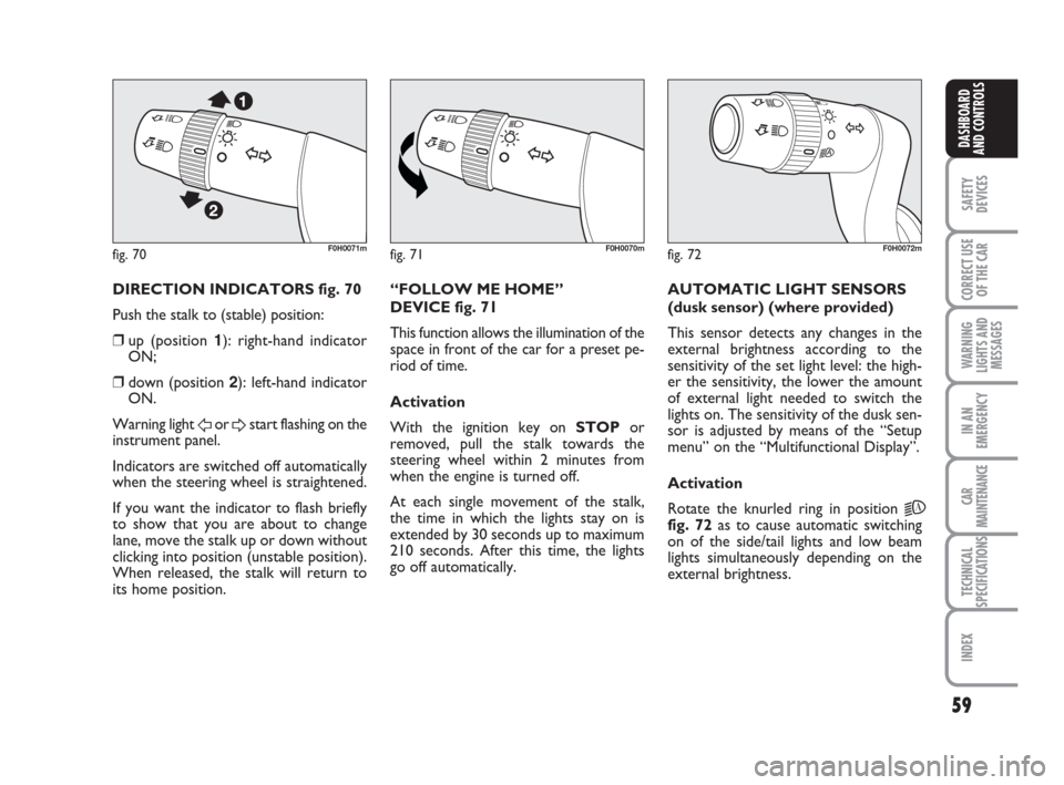
DIRECTION INDICATORS fig. 70
Push the stalk to (stable) position:
❒up (position 1): right-hand indicator
ON;
❒down (position 2): left-hand indicator
ON.
Warning light
For Dstart flashing on the
instrument panel.
Indicators are switched off automatically
when the steering wheel is straightened.
If you want the indicator to flash briefly
to show that you are about to change
lane, move the stalk up or down without
clicking into position (unstable position).
When released, the stalk will return to
its home position.“FOLLOW ME HOME”
DEVICE fig. 71
This function allows the illumination of the
space in front of the car for a preset pe-
riod of time.
Activation
With the ignition key on STOPor
removed, pull the stalk towards the
steering wheel within 2 minutes from
when the engine is turned off.
At each single movement of the stalk,
the time in which the lights stay on is
extended by 30 seconds up to maximum
210 seconds. After this time, the lights
go off automatically. AUTOMATIC LIGHT SENSORS
(dusk sensor) (where provided)
This sensor detects any changes in the
external brightness according to the
sensitivity of the set light level: the high-
er the sensitivity, the lower the amount
of external light needed to switch the
lights on. The sensitivity of the dusk sen-
sor is adjusted by means of the “Setup
menu” on the “Multifunctional Display”.
Activation
Rotate the knurled ring in position
2A
fig. 72as to cause automatic switching
on of the side/tail lights and low beam
lights simultaneously depending on the
external brightness.
036-092 idea GB 1 ed 10-07-2008 16:12 Pagina 59
Page 61 of 210
60
SAFETY
DEVICES
CORRECT USE
OF THE CAR
WARNING
LIGHTS AND
MESSAGES
IN AN
EMERGENCY
CAR
MAINTENANCE
TECHNICAL
SPECIFICATIONS
INDEX
DASHBOARD
AND CONTROLS
WINDOW WASHING
WINDSCREEN
WASHER/WIPER
The device can work only when the igni-
tion key is on MAR.
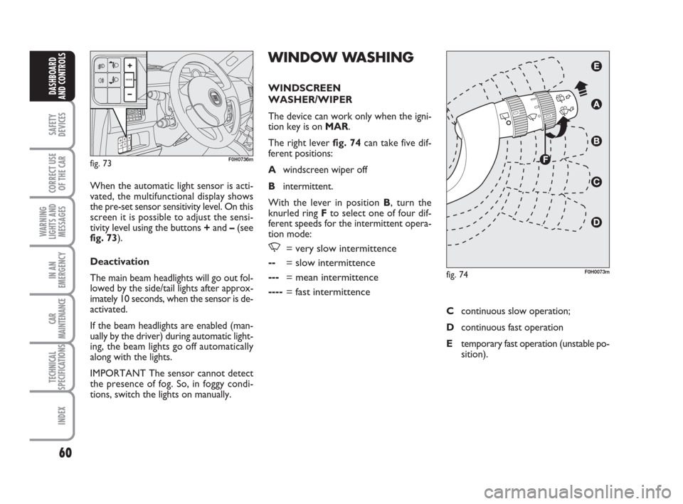
The right lever fig. 74can take five dif-
ferent positions:
Awindscreen wiper off
Bintermittent.
With the lever in position B, turn the
knurled ring Fto select one of four dif-
ferent speeds for the intermittent opera-
tion mode:
,= very slow intermittence
--= slow intermittence
---= mean intermittence
----= fast intermittence
When the automatic light sensor is acti-
vated, the multifunctional display shows
the pre-set sensor sensitivity level. On this
screen it is possible to adjust the sensi-
tivity level using the buttons +and –(see
fig. 73).
Deactivation
The main beam headlights will go out fol-
lowed by the side/tail lights after approx-
imately 10 seconds, when the sensor is de-
activated.
If the beam headlights are enabled (man-
ually by the driver) during automatic light-
ing, the beam lights go off automatically
along with the lights.
IMPORTANT The sensor cannot detect
the presence of fog. So, in foggy condi-
tions, switch the lights on manually.
fig. 73F0H0736m
fig. 74F0H0073m
Ccontinuous slow operation;
Dcontinuous fast operation
Etemporary fast operation (unstable po-
sition).
036-092 idea GB 1 ed 10-07-2008 16:12 Pagina 60
Page 62 of 210
61
SAFETY
DEVICES
CORRECT USE
OF THE CAR
WARNING
LIGHTS AND
MESSAGES
IN AN
EMERGENCY
CAR
MAINTENANCE
TECHNICAL
SPECIFICATIONS
INDEX
DASHBOARD
AND CONTROLS
Operation in position Eis limited to the
time during which the lever is kept in that
position manually. When released, the
stalk will return to position Aand the
wiper will be automatically stopped.
IMPORTANT Replace wiper blades as
specified in section “Car maintenance”.RAIN SENSOR
(where provided)
The rain sensor is located behind the dri-
ving mirror in contact with the windscreen
and has the purpose of automatically ad-
just the frequency of the windscreen
wiper strokes as to the rain intensity.
IMPORTANT Keep the window clean in
the sensor area.
Activation
Move the right lever down by one click.
The activation of the rain sensor is sig-
nalled by a control acquisition “stroke”.
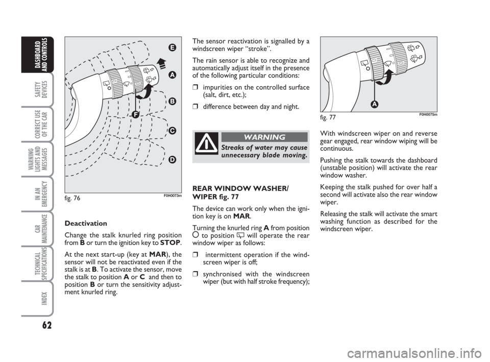
Turn the knurled ring F-fig. 76to increase
the rain sensor sensitivity.
The increase of the sensitivity of the rain
sensor is signalled by a control and acqui-
sition “stroke”.
By operating the windscreen washer with
the rain sensor enabled, a smart washing
cycle is carried out, without the addition-
al stroke after 5 seconds; once complet-
ed, the sensor resumes its regular auto-
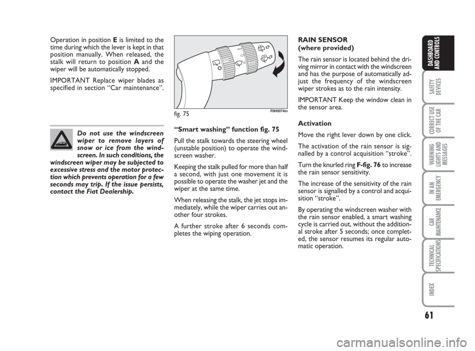
matic operation. “Smart washing” function fig. 75
Pull the stalk towards the steering wheel
(unstable position) to operate the wind-
screen washer.
Keeping the stalk pulled for more than half
a second, with just one movement it is
possible to operate the washer jet and the
wiper at the same time.
When releasing the stalk, the jet stops im-
mediately, while the wiper carries out an-
other four strokes.
A further stroke after 6 seconds com-
pletes the wiping operation. Do not use the windscreen
wiper to remove layers of
snow or ice from the wind-
screen. In such conditions, the
windscreen wiper may be subjected to
excessive stress and the motor protec-
tion which prevents operation for a few
seconds may trip. If the issue persists,
contact the Fiat Dealership.
fig. 75F0H0074m
036-092 idea GB 1 ed 10-07-2008 16:12 Pagina 61
Page 63 of 210
62
SAFETY
DEVICES
CORRECT USE
OF THE CAR
WARNING
LIGHTS AND
MESSAGES
IN AN
EMERGENCY
CAR
MAINTENANCE
TECHNICAL
SPECIFICATIONS
INDEX
DASHBOARD
AND CONTROLS
The sensor reactivation is signalled by a
windscreen wiper “stroke”.
The rain sensor is able to recognize and
automatically adjust itself in the presence
of the following particular conditions:
❒impurities on the controlled surface
(salt, dirt, etc.);
❒difference between day and night.
Deactivation
Change the stalk knurled ring position
from Bor turn the ignition key to STOP.
At the next start-up (key at MAR), the
sensor will not be reactivated even if the
stalk is at B. To activate the sensor, move
the stalk to position Aor Cand then to
position Bor turn the sensitivity adjust-
ment knurled ring.
fig. 76F0H0073m
Streaks of water may cause
unnecessary blade moving.
WARNINGWith windscreen wiper on and reverse
gear engaged, rear window wiping will be
continuous.
Pushing the stalk towards the dashboard
(unstable position) will activate the rear
window washer.
Keeping the stalk pushed for over half a
second will activate also the rear window
wiper.
Releasing the stalk will activate the smart
washing function as described for the
windscreen wiper.
fig. 77F0H0075m
REAR WINDOW WASHER/
WIPER fig. 77
The device can work only when the igni-
tion key is on MAR.
Turning the knurled ring Afrom position
åto position 'will operate the rear
window wiper as follows:
❒intermittent operation if the wind-
screen wiper is off;
❒synchronised with the windscreen
wiper (but with half stroke frequency);
036-092 idea GB 1 ed 10-07-2008 16:12 Pagina 62
Page 89 of 210

88
SAFETY
DEVICES
CORRECT USE
OF THE CAR
WARNING
LIGHTS AND
MESSAGES
IN AN
EMERGENCY
CAR
MAINTENANCE
TECHNICAL
SPECIFICATIONS
INDEX
DASHBOARD
AND CONTROLS
PARKING SENSORS
(where provided)
The parking sensors are located on the
rear bumper fig. 131and their function is
to inform the driver, through an inter-
mittent buzzer, about the presence of ob-
stacles in the rear part of the car.
ACTIVATION
The sensors are automatically activated
when the reverse gear is engaged.
As the distance from the obstacle behind
the car decreases, the acoustic alarm be-
comes more frequent. BUZZER WARNINGS
Engaging reverse gear, if an obstacle is lo-
cated in the area behind the car, an inter-
mittent sound signal activates.
The acoustic signal:
❒becomes louder as the reduction of
distance between the car and the ob-
stacle decreases;
❒becomes continuous when the dis-
tance between the car and the obsta-
cle is less that 30 cm and stops if the
distance raises;
❒is constant if the distance is unvaried.
If this situation takes place for side sen-
sors, the signal is stopped after about
3 seconds to prevent sound indica-
tions when performing manoeuvres
near walls.
fig. 131F0H0744m
Direction distances
The central detecting range varies ac-
cording to car engine type/set-up version:
detection range is 140 cm. For small size
obstacles (or in case of parking deterrent
blocks that are round shaped) it is 70 cm.
Side detecting range is 60 cm.
If several obstacles are detected, the con-
trol unit indicates the nearest one.
036-092 idea GB 1 ed 10-07-2008 16:12 Pagina 88
Page 90 of 210
89
SAFETY
DEVICES
CORRECT USE
OF THE CAR
WARNING
LIGHTS AND
MESSAGES
IN AN
EMERGENCY
CAR
MAINTENANCE
TECHNICAL
SPECIFICATIONS
INDEX
DASHBOARD
AND CONTROLS
FAILURE WARNINGS
See the “Warning lights and messages”
chapter.
OPERATION WITH TRAILER
The system is preset for deactivating au-
tomatically when the trailer electric ca-
ble plug is fitted into the car tow hook
socket.
Sensors are reactivated when removing
the trailer cable plug.For proper operation, the
parking sensors set on the
bumpers shall be clean from
mud, dirt, snow or ice. When
cleaning the sensors, take the utmost
care to prevent their damaging; do not
use therefore dry or rough clothes. Sen-
sors shall be washed with clean water
and car detergent, if required. In wash-
ing stations, clean sensors quickly keep-
ing the vapour jet/high pressure wash-
ing nozzles at 10 cm at least from the
sensors.
Parking manoeuvres howev-
er are always under the dri-
ver’s responsibility that shall always
check the absence of people, animals
or objects in the manoeuvre space.
This system is just a help for the dri-
ver but he shall never reduce impor-
tant during dangerous manoeuvres
even if performed at low speed.
WARNING
GENERAL WARNINGS
❒When parking, take the utmost care
to obstacles set above or under the
sensors.
❒Objects set close to car rear part, un-
der certain circumstances are not de-
tected and could therefore cause dam-
ages to the car.
❒Indications sent by the sensor can be
altered by dirt, snow or ice deposit-
ed on the sensors or by ultrasound
systems (e.g.: truck pneumatic brakes
or pneumatic hammers) set nearby the
car.
036-092 idea GB 1 ed 10-07-2008 16:12 Pagina 89
Page 93 of 210
PROTECTING
THE ENVIRONMENT
The devices for curtailing petrol engine
emissions are the following:
❒three-way catalytic converter;
❒Lambda sensor;
❒fuel evaporation system.
In addition, do not let the engine run, even
for a test, with one or more spark plugs
disconnected.
The devices for curtailing diesel fuel en-
gine emissions are the following:
❒oxidising catalytic converter;
❒exhaust gas recirculation system
(E.G.R.).
❒diesel particulate filter (DPF)DIESEL PARTICULATE
FILTER (DPF) (for 1.3 Multijet
versions 90 HP)
The Diesel Particulate Filter is a mechan-
ical filter, integral with the exhaust system,
that physically traps particulates present
in the exhaust gases of Diesel engines.
The diesel particular filter has been adopt-
ed to eliminate almost totally particulates
in compliance with current / future law
regulations.
During normal use of the vehicle, the en-
gine control unit records a set of data (e.g.:
travel time, type of route, temperatures,
etc.) and it will then calculate how much
particulates has been trapped by the filter.
Since this filter physically traps particulates,
it shall be cleaned (reclaimed) at regular
intervals by burning carbon particles.
Reclaiming procedure is controlled auto-
matically by the engine control unit ac-
cording to the filter conditions and the
conditions of use of the vehicle.
During normal service the
catalyst reaches high tem-
peratures. Do not therefore park the
car over inflammable materials (grass,
dry leaves, pine needles, etc.): fire
hazard.
WARNING
During reclaiming the following phenom-
ena could take place: idling slight increase,
fan activation, slight smoke increase, high
exhaust temperatures. These situations
shall not be considered as faults and they
do not affect vehicle performance and en-
vironment.
If the dedicated message is displayed, re-
fer to paragraph “Warning lights and mes-
sages”.
DASHBOARD
AND CONTROLS
INDEX
TECHNICAL
SPECIFICATIONS
CAR
MAINTENANCE
IN AN
EMERGENCY
WARNING
LIGHTS AND
MESSAGES
CORRECT USE
OF THE CAR
SAFETY
DEVICES
92
036-092 idea GB 1 ed 10-07-2008 16:12 Pagina 92
Page 131 of 210
130
IN AN
EMERGENCY
CAR
MAINTENANCE
TECHNICAL
SPECIFICATIONS
INDEX
DASHBOARD
AND CONTROLS
SAFETY
DEVICES
CORRECT USE
OF THE CAR
WARNING
LIGHTS AND
MESSAGES
GENERAL FAILURE
INDICATION
(amber)
The warning light turns on in the
following circumstances.
External light failure
The warning light comes on (on some ver-
sions only) when a failure is detected in
one of the following lights:
– tail lights
– stop lights (excluding 3rd stop)
– rear fog lights
– direction indicators
– plate lights.
The fault identified in the lights above may
be due to: one or more burnt lamps, a
blown protection fuse or interruption of
the electrical connection.
The display will show the dedicated mes-
sage.
è
Fresh air filter clogged
(where provided)
The warning light turns on when the par-
ticulate filter is clogged and the driving
conditions do not enable automatic acti-
vation of the regeneration procedure.
To allow the regeneration procedure,
keep the car running until the warning light
turns off.
The display will show the dedicated mes-
sage.
Engine oil pressure sensor failure
The warning light turns on when a failure
is detected in the engine oil pressure sen-
sor. Go to a Fiat Dealership as soon as
possible.Twilight/rain sensor failure
The warning light turns on when a failure
is detected in the twilight/rain sensors. Go
to a Fiat Dealership as soon as possible.
The display will show the dedicated mes-
sage.
Fuel cut-off switch tripped
The warning light comes on when the fu-
el cut-off switch trips.
The display will show the dedicated mes-
sage.
Speed limit exceeded
The display shows the dedicated message
when the car exceeds the set speed limit
(see “Multifunction Display” in section
“Dashboard and controls”).
123-132 idea GB 1 ed 10-07-2008 8:29 Pagina 130