technical specifications FIAT LINEA 2007 1.G Owners Manual
[x] Cancel search | Manufacturer: FIAT, Model Year: 2007, Model line: LINEA, Model: FIAT LINEA 2007 1.GPages: 230, PDF Size: 3.31 MB
Page 145 of 230
144
IN AN
EMERGENCY
CAR
MAINTENANCE
TECHNICAL
SPECIFICATIONS
INDEX
DASHBOARD
AND CONTROLS
SAFETY
DEVICES
CORRECT USE
OF THE
CAR
WARNING
LIGHTS AND
MESSAGES
ASR SYSTEM
(versions with multifunction display)
The ASR system can be turned off by
pressing the button ASR OFF.
A dedicated message will appear on the
display to inform the driver that the sys-
tem has been switched off. The LED on
the button will light up at the same time. POSSIBLE PRESENCE OF ICE
ON THE ROAD
(versions with multifunction display)
This indication starts flashing when the
outside temperature reaches or falls be-
low 3°C to warn the driver of the possi-
ble presence of ice on the road.
The display will show the dedicated mes-
sage.
LIMITED RANGE
(versions with multifunction display)
The display will show the dedicated mes-
sage to warn the driver that the cruising
range is less than 50 km. Press ASR OFF again: the LED on the
button will go out and a dedicated mes-
sage will appear on the display to inform
uses that the system has been switched
back on.
Page 146 of 230
145
WARNING
LIGHTS AND
MESSAGES
CAR
MAINTENANCE
TECHNICAL
SPECIFICATIONS
INDEX
DASHBOARD
AND CONTROLS
SAFETY
DEVICES
CORRECT USE
OF THE
CAR
IN AN
EMERGENCY
STARTING THE ENGINE ................................................. 146
IF A TYRE IS PUNCTURED............................................... 147
QUICK TYRE REPAIR KIT
FIX & GO automatic............................................................. 153
WHEN NEEDING TO CHANGE A BULB ................... 158
IF AN EXTERIOR LIGHT BURNS OUT.......................... 160
IF AN INTERIOR LIGHT BURNS OUT.......................... 165
IF A FUSE BLOWS................................................................ 167
IF THE BATTERY IS FLAT .................................................. 174
LIFTING THE CAR............................................................... 175
TOWING THE CAR ........................................................... 175
II I
N N
A A
N N
E E
M M
E E
R R
G G
E E
N N
C C
Y Y
Page 147 of 230
146
WARNING
LIGHTS AND
MESSAGES
CAR
MAINTENANCE
TECHNICAL
SPECIFICATIONS
IINDEX
DASHBOARD
AND CONTROLS
SAFETY
DEVICES
CORRECT USE
OF THE
CAR
IN AN
EMERGENCY
STARTING THE
ENGINE
EMERGENCY START-UP
Go to a Fiat Dealership immediately if in-
strument panel warning light
Ycomes
on steady.
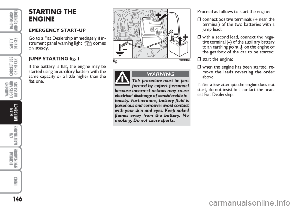
JUMP STARTING fig. 1
If the battery is flat, the engine may be
started using an auxiliary battery with the
same capacity or a little higher than the
flat one. Proceed as follows to start the engine:
❒connect positive terminals (+near the
terminal) of the two batteries with a
jump lead;
❒with a second lead, connect the nega-
tive terminal (–) of the auxiliary battery
to an earthing point
Eon the engine or
the gearbox of the car to be started;
❒start the engine;
❒when the engine has been started, re-
move the leads reversing the order
above.
If after a few attempts the engine does not
start, do not insist but contact the near-
est Fiat Dealership.
This procedure must be per-
formed by expert personnel
because incorrect actions may cause
electrical discharge of considerable in-
tensity. Furthermore, battery fluid is
poisonous and corrosive: avoid contact
with your skin and eyes. Keep naked
flames away from the battery. No
smoking. Do not cause sparks.
WARNING
fig. 1F0R0242m
Page 148 of 230
147
WARNING
LIGHTS AND
MESSAGES
CAR
MAINTENANCE
TECHNICAL
SPECIFICATIONS
INDEX
DASHBOARD
AND CONTROLS
SAFETY
DEVICES
CORRECT USE
OF THE
CAR
IN AN
EMERGENCY
IMPORTANT Never connect the negative
terminals of the two batteries directly:
sparks could ignite explosive gas released
from the battery. If the auxiliary battery is
installed on another car, prevent acciden-
tal contact between metallic parts of the
two cars.BUMP STARTING
Never jump start the engine by pushing,
towing or driving downhill. This could
cause a flow of fuel into the catalytic con-
verter and damage it beyond repair.
IMPORTANT Remember that the brake
booster and the power steering system
are not operating until the engine is start-
ed, a greater effort will therefore be re-
quired to press the brake pedal or turn
the steering wheel.REPLACING A WHEEL
GENERAL INSTRUCTIONS
Wheel changing and correct use of the
jack and spare wheel call for some pre-
cautions as listed below.
Indicate that the car is sta-
tionary according to the laws
in force: hazard lights, triangle, etc.
Passengers should leave the car, par-
ticularly if it is very loaded and wait
for the wheel to be changed away
from on-coming traffic. Apply the
handbrake.
WARNING
Page 149 of 230
148
WARNING
LIGHTS AND
MESSAGES
CAR
MAINTENANCE
TECHNICAL
SPECIFICATIONS
IINDEX
DASHBOARD
AND CONTROLS
SAFETY
DEVICES
CORRECT USE
OF THE
CAR
IN AN
EMERGENCY
The spare wheel is specific
for your car. Do not use it on
cars of different models. Do not use
spare wheels of different models on
your car. The wheel bolts are specif-
ic for your car. Do not use them on
cares of different models. Do not use
bolts of different models on your car.
WARNING
Repair and refit the standard
wheel as soon as possible.
Do not apply grease to the bolt
threading before assembly: the bolts
could come loose unexpectedly.
WARNING
The jack may only be used to
replace wheels on the car
which it equips or other cars of the
same model. Never use the jack for
other purposes, such as lifting other
car models. Never use the jack to car-
ry out repairs under the car. Incorrect
positioning of the jack may cause the
car to fall. Do not use the jack for
loads higher than those shown on the
label.
WARNING
Incorrect wheel cup assem-
bly may cause it to come off
when the car is travelling. Never tam-
per with the inflation valve. Never in-
troduce tools of any kind between rim
and tyre. Check tyre and spare wheel
pressure regularly referring to the val-
ues shown in the “Technical Specifi-
cations” chapter.
WARNING
Important notes:
❒the jack weighs 1.76 kg;
❒the jack requires no adjustment;
❒the jack cannot be repaired: replace
with an original spare part if damaged;
❒no tool other than its handle may be fit-
ted on the jack.
Page 150 of 230
149
WARNING
LIGHTS AND
MESSAGES
CAR
MAINTENANCE
TECHNICAL
SPECIFICATIONS
INDEX
DASHBOARD
AND CONTROLS
SAFETY
DEVICES
CORRECT USE
OF THE
CAR
IN AN
EMERGENCY
To change a wheel proceed as
follows:
❒stop the car in a position so that it is
not a danger for on-coming traffic and
where you can replace the wheel safe-
ly. The ground must be flat and com-
pact;
❒stop the engine off and pull up the hand-
brake;
❒engage first gear or reverse;
❒wear the reflecting safety jacket (com-
pulsory by law in certain countries) be-
fore getting out of the car;
❒open the tailgate and lift the mat;
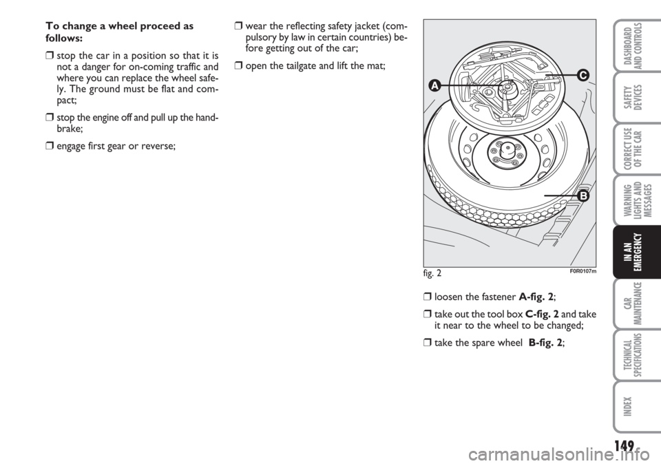
❒loosen the fastener A-fig. 2;
❒take out the tool box C-fig. 2and take
it near to the wheel to be changed;
❒take the spare wheel B-fig. 2;
fig. 2F0R0107m
Page 151 of 230
150
WARNING
LIGHTS AND
MESSAGES
CAR
MAINTENANCE
TECHNICAL
SPECIFICATIONS
IINDEX
DASHBOARD
AND CONTROLS
SAFETY
DEVICES
CORRECT USE
OF THE
CAR
IN AN
EMERGENCY
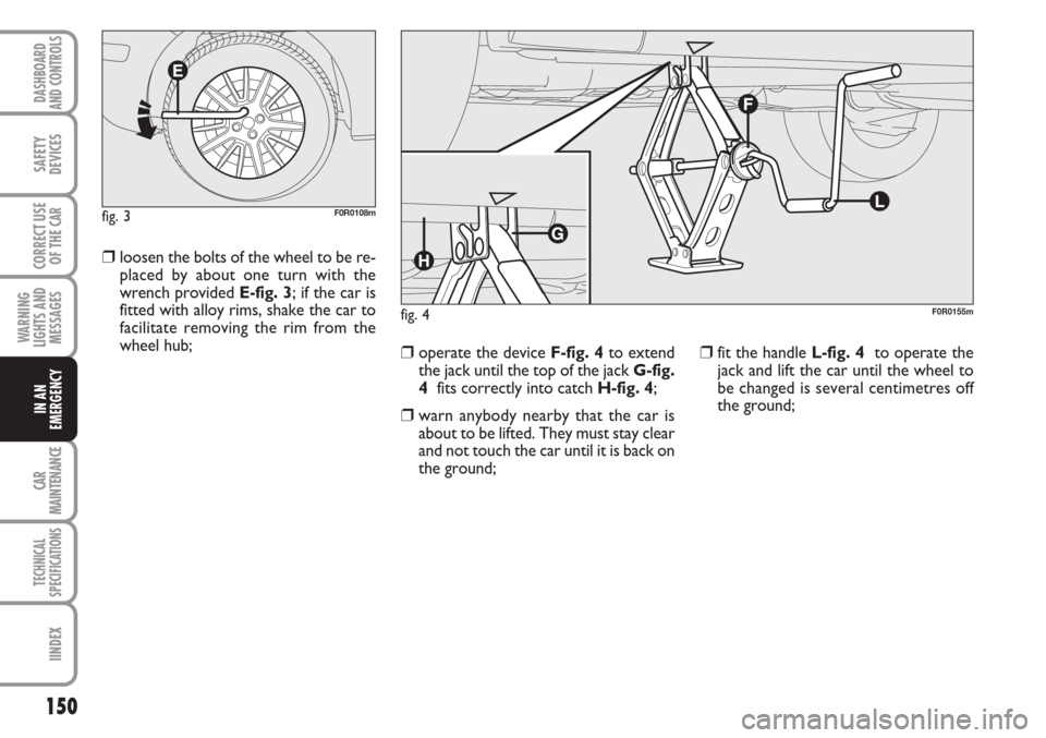
❒loosen the bolts of the wheel to be re-
placed by about one turn with the
wrench provided E-fig. 3; if the car is
fitted with alloy rims, shake the car to
facilitate removing the rim from the
wheel hub;
❒operate the device F-fig. 4to extend
the jack until the top of the jack G-fig.
4fits correctly into catch H-fig. 4;
❒warn anybody nearby that the car is
about to be lifted. They must stay clear
and not touch the car until it is back on
the ground;
❒fit the handle L-fig. 4to operate the
jack and lift the car until the wheel to
be changed is several centimetres off
the ground;
fig. 3F0R0108m
fig. 4F0R0155m
Page 152 of 230
151
WARNING
LIGHTS AND
MESSAGES
CAR
MAINTENANCE
TECHNICAL
SPECIFICATIONS
INDEX
DASHBOARD
AND CONTROLS
SAFETY
DEVICES
CORRECT USE
OF THE
CAR
IN AN
EMERGENCY
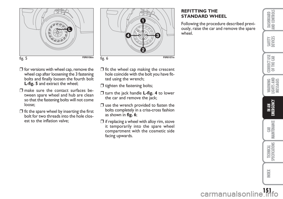
❒for versions with wheel cap, remove the
wheel cap after loosening the 3 fastening
bolts and finally loosen the fourth bolt
L-fig. 5and extract the wheel;
❒make sure the contact surfaces be-
tween spare wheel and hub are clean
so that the fastening bolts will not come
loose;
❒fit the spare wheel by inserting the first
bolt for two threads into the hole clos-
est to the inflation valve;
❒fit the wheel cap making the crescent
hole coincide with the bolt you have fit-
ted using the wrench;
❒tighten the fastening bolts;
❒turn the jack handle L-fig. 4to lower
the car and remove the jack;
❒use the wrench provided to fasten the
bolts completely in a criss-cross fashion
as shown in fig. 6;
❒if replacing a wheel with alloy rim, stove
it temporarily into the spare wheel
compartment with the cosmetic side
facing upwards.REFITTING THE
STANDARD WHEEL
Following the procedure described previ-
ously, raise the car and remove the spare
wheel.
fig. 5F0R0156mfig. 6F0R0157m
Page 153 of 230
152
WARNING
LIGHTS AND
MESSAGES
CAR
MAINTENANCE
TECHNICAL
SPECIFICATIONS
IINDEX
DASHBOARD
AND CONTROLS
SAFETY
DEVICES
CORRECT USE
OF THE
CAR
IN AN
EMERGENCY
Versions with steel rims
Proceed as follows:
❒make sure the contact surfaces be-
tween spare wheel and hub are clean
so that the fastening bolts will not come
loose;
❒fit the standard wheel by inserting the
first bolt for two threads into the hole
closest to the inflation valve;
❒fit the wheel cap making the lunette
hole coincide with the bolt you have fit-
ted then, fit the other 3 bolts;
❒using the wrench provided, tighten the
fastening bolts;
❒lower the car and remove the jack;
❒using the wrench provided, fully tight-
en the bolts in the sequence shown
previously in the figure.Versions with alloy rims
Proceed as follows:
❒insert the wheel on the hub and using
the wrench provided tighten the bolts;
❒lower the car and remove the jack;
❒using the wrench provided, fully tight-
en the bolts in the sequence shown in
the figure.When you have finished
❒stow the spare wheel in the space pro-
vided in the boot;
❒fit the jack partially open in its box
C-fig. 2forcing it lightly to prevent it
from vibrating when travelling;
❒put the tools back into their places in
the container;
❒stow the container C-fig. 2, complete
with tools in the spare wheel;
❒tight the tool box fastener A-fig. 2;
❒reposition the mat in the boot.
Page 154 of 230
153
WARNING
LIGHTS AND
MESSAGES
CAR
MAINTENANCE
TECHNICAL
SPECIFICATIONS
INDEX
DASHBOARD
AND CONTROLS
SAFETY
DEVICES
CORRECT USE
OF THE
CAR
IN AN
EMERGENCY
QUICK TYRE REPAIR KIT
FIX & GO automatic
The Fix & Go automatic quick tyre repair
kit is placed in the boot under the mat.
The kit fig. 7includes:
❒cylinder A containing sealant and fitted
with:
– filling pipe B;
– an adhesive label Cwith the mes-
sage “max. 80 km/h” to be apply in
a position clearly visible by the dri-
ver (on the dashboard) after repair-
ing the tyre;
❒instruction booklet (see fig. 8), to be
used for prompt and proper use of the
quick repair kit and to be then handed
to the personnel charged with handling
the treated tyre;
❒compressor D-fig. 7including gauge
and connections;
❒a pair of protection gloves located in
the side space of the compressor;
❒adapters for inflating different elements.
fig. 7F0R0158m
The quick repair kit also contains a screw-
driver and a tow ring.
fig. 8F0R0159m
Hand over the instruction
booklet to the personnel
charged with treating the tyre re-
paired with the kit.
WARNING