technical specifications FIAT LINEA 2007 1.G Owners Manual
[x] Cancel search | Manufacturer: FIAT, Model Year: 2007, Model line: LINEA, Model: FIAT LINEA 2007 1.GPages: 230, PDF Size: 3.31 MB
Page 155 of 230
154
WARNING
LIGHTS AND
MESSAGES
CAR
MAINTENANCE
TECHNICAL
SPECIFICATIONS
IINDEX
DASHBOARD
AND CONTROLS
SAFETY
DEVICES
CORRECT USE
OF THE
CAR
IN AN
EMERGENCY
IMPORTANT INFORMATION:
The sealing fluid of the quick tyre repair
kit is effective with external temperatures
between -20 °C and +50 °C.
The sealing fluid will expire.
Do not operate the com-
pressor for longer than 20
consecutive minutes. Risk of over-
heating. The quick repair kit is not
suitable for definitive repairs. The
tyres may only be repaired tem-
porarily.
WARNING
In the event of a puncture
caused by foreign bodies, the
kit may be used to repair
tyres showing damages on the
track or shoulder up to max 4 mm di-
ameter.
The kit cannot be used to re-
pair damage to the tyre side-
wall. Do not use the quick repair kit
if the tyre was damaged by running
on a flat.
WARNING
The damage cannot be re-
paired with the kit if the
wheel rim is damaged (deformation
of the channel causing leakage of air).
Do not remove the foreign body
(screw or nail) from the tyre.
WARNING
Page 156 of 230
155
WARNING
LIGHTS AND
MESSAGES
CAR
MAINTENANCE
TECHNICAL
SPECIFICATIONS
INDEX
DASHBOARD
AND CONTROLS
SAFETY
DEVICES
CORRECT USE
OF THE
CAR
IN AN
EMERGENCY
INFLATION PROCEDURE
The cylinder contains ethyl
glycol. Contains latex: may
cause an allergic reaction. Harmful if
swallowed. Irritant for the eye. May
cause sensitization by inhalation or
contact. Avoid contact with your eyes,
skin and clothes. In the event of con-
tact, wash immediately with plenty of
water. Do not induce vomit if swal-
lowed. Rinse your mouth and drink
plenty of water. Call a doctor imme-
diately. Keep away from children. The
product must not be used by asth-
matics. Do not breath in the vapours
during insertion and suction. Call a
doctor immediately if allergic reactions
are noted. Store the cylinder in the
specific compartment, away from
sources of heat. The sealing fluid will
expire.
WARNINGReplace the cylinder contain-
ing the sealant after the ex-
piration date. Dispose of the
cylinder and the sealant liq-
uid properly. Dispose according to the
national and local laws in force.
Put on the protection gloves
provided together with quick
tyre repair kit.
WARNING
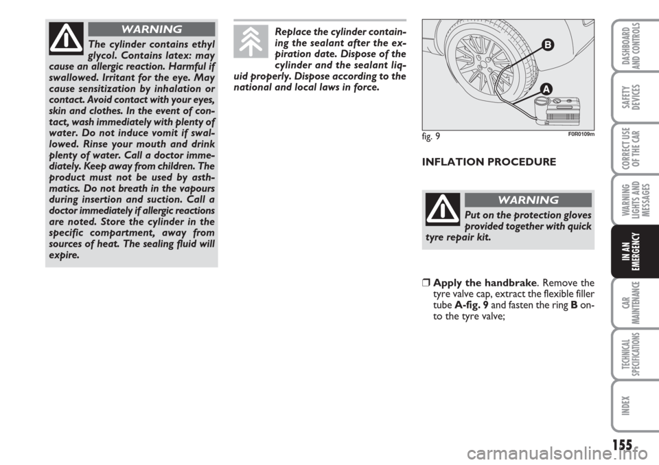
❒Apply the handbrake. Remove the
tyre valve cap, extract the flexible filler
tube A-fig. 9and fasten the ring Bon-
to the tyre valve;
fig. 9F0R0109m
Page 157 of 230
156
WARNING
LIGHTS AND
MESSAGES
CAR
MAINTENANCE
TECHNICAL
SPECIFICATIONS
IINDEX
DASHBOARD
AND CONTROLS
SAFETY
DEVICES
CORRECT USE
OF THE
CAR
IN AN
EMERGENCY
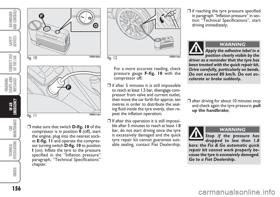
❒make sure that switch D-fig. 10of the
compressor is in position 0(off), start
the engine, plug into the nearest sock-
et E-fig. 11and operate the compres-
sor turning switch D-fig. 10to position
I(on). Inflate the tyre to the pressure
specified in the “Inflation pressure”
paragraph, “Technical Specifications”
chapter. For a more accurate reading, check
pressure gauge F-fig. 10with the
compressor off;
❒if after 5 minutes it is still impossible
to reach at least 1.5 bar, disengage com-
pressor from valve and current outlet,
then move the car forth for approx. ten
metres in order to distribute the seal-
ing fluid inside the tyre evenly, then re-
peat the inflation operation;
❒If after this operation it is still impossi-
ble after 5 minutes to reach at least 1.8
bar, do not start driving since the tyre
is excessively damaged and the quick
tyre repair kit cannot guarantee suit-
able sealing, contact Fiat Dealership;
❒if reaching the tyre pressure specified
in paragraph “Inflation pressure” in sec-
tion “Technical Specifications”, start
driving immediately;
fig. 10F0R0160m
fig. 11F0R0113m
fig. 12F0R0110m
Apply the adhesive label in a
position clearly visible by the
driver as a reminder that the tyre has
been treated with the quick repair kit.
Drive carefully, particularly on bends.
Do not exceed 80 km/h. Do not ac-
celerate or brake suddenly.
WARNING
❒after driving for about 10 minutes stop
and check again the tyre pressure; pull
up the handbrake;
Stop if the pressure has
dropped to less than 1.8
bars: the Fix & Go automatic quick
repair kit cannot work properly be-
cause the tyre is excessively damaged.
Go to a Fiat Dealership.
WARNING
Page 158 of 230
157
WARNING
LIGHTS AND
MESSAGES
CAR
MAINTENANCE
TECHNICAL
SPECIFICATIONS
INDEX
DASHBOARD
AND CONTROLS
SAFETY
DEVICES
CORRECT USE
OF THE
CAR
IN AN
EMERGENCY
❒if at least 1.8 bar pressure is read, re-
store proper pressure (with engine
running and handbrake on) and restart;
❒drive with the utmost care to the near-
est Fiat Dealership.
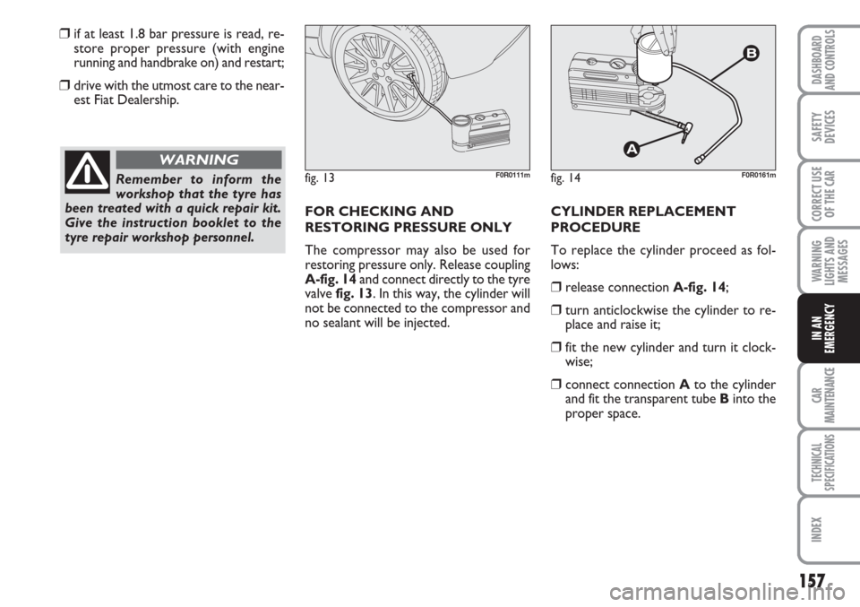
FOR CHECKING AND
RESTORING PRESSURE ONLY
The compressor may also be used for
restoring pressure only. Release coupling
A-fig. 14and connect directly to the tyre
valve fig. 13. In this way, the cylinder will
not be connected to the compressor and
no sealant will be injected. CYLINDER REPLACEMENT
PROCEDURE
To replace the cylinder proceed as fol-
lows:
❒release connection A-fig. 14;
❒turn anticlockwise the cylinder to re-
place and raise it;
❒fit the new cylinder and turn it clock-
wise;
❒connect connection Ato the cylinder
and fit the transparent tube Binto the
proper space.
Remember to inform the
workshop that the tyre has
been treated with a quick repair kit.
Give the instruction booklet to the
tyre repair workshop personnel.
WARNING
fig. 13F0R0111mfig. 14F0R0161m
Page 159 of 230
158
WARNING
LIGHTS AND
MESSAGES
CAR
MAINTENANCE
TECHNICAL
SPECIFICATIONS
IINDEX
DASHBOARD
AND CONTROLS
SAFETY
DEVICES
CORRECT USE
OF THE
CAR
IN AN
EMERGENCY
WHEN NEEDING TO
CHANGE A BULB
GENERAL INSTRUCTIONS
❒When a bulb is not working, check that
the corresponding fuse is intact before
replacing it: refer to the “If a fuse
blows” paragraph in this chapter for
fuse location.
❒before changing a bulb check the con-
tacts for oxidation;
❒burnt bulbs must be replaced by others
of the same type and power;
❒always check the height of the headlight
beam after changing a bulb, for reasons
of safety.
IMPORTANT A slight misting may appear
on the internal surface of the headlight:
this does not indicate a fault and is caused
by low temperature and the degree of hu-
midity in the air. Misting will rapidly dis-
appear when the headlights are switched
on. The presence of drop inside the head-
lights indicates infiltration of water. Go to
a Fiat Dealership.
TYPES OF BULBS
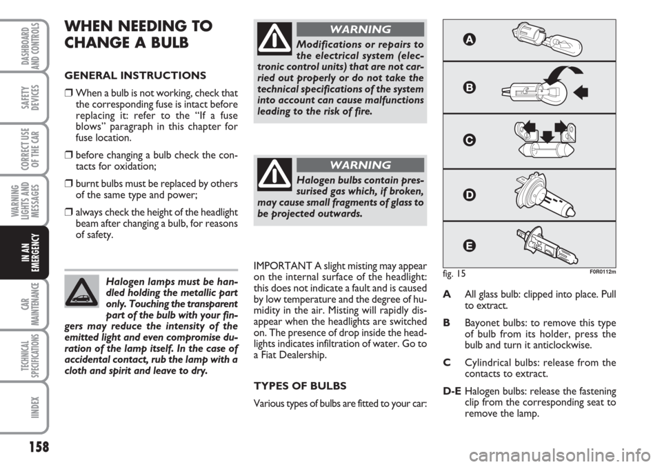
Various types of bulbs are fitted to your car:AAll glass bulb: clipped into place. Pull
to extract.
BBayonet bulbs: to remove this type
of bulb from its holder, press the
bulb and turn it anticlockwise.
CCylindrical bulbs: release from the
contacts to extract.
D-EHalogen bulbs: release the fastening
clip from the corresponding seat to
remove the lamp. Halogen lamps must be han-
dled holding the metallic part
only. Touching the transparent
part of the bulb with your fin-
gers may reduce the intensity of the
emitted light and even compromise du-
ration of the lamp itself. In the case of
accidental contact, rub the lamp with a
cloth and spirit and leave to dry.
Modifications or repairs to
the electrical system (elec-
tronic control units) that are not car-
ried out properly or do not take the
technical specifications of the system
into account can cause malfunctions
leading to the risk of fire.
WARNING
Halogen bulbs contain pres-
surised gas which, if broken,
may cause small fragments of glass to
be projected outwards.
WARNING
fig. 15F0R0112m
Page 160 of 230
159
WARNING
LIGHTS AND
MESSAGES
CAR
MAINTENANCE
TECHNICAL
SPECIFICATIONS
INDEX
DASHBOARD
AND CONTROLS
SAFETY
DEVICES
CORRECT USE
OF THE
CAR
IN AN
EMERGENCY
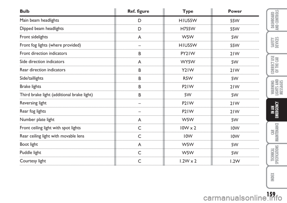
Bulb Ref. figure Type Power
Main beam headlights
Dipped beam headlights
Front sidelights
Front fog lights (where provided)
Front direction indicators
Side direction indicators
Rear direction indicators
Side/taillights
Brake lights
Third brake light (additional brake light)
Reversing light
Rear fog lights
Number plate light
Front ceiling light with spot lights
Rear ceiling light with movable lens
Boot light
Puddle light
Courtesy light H1U55W
H755W
W5W
H1U55W
PY21W
WY5W
Y21W
R5W
P21W
5W
P21W
P21W
W5W
10W x 2
10W
W5W
W5W
1.2W x 2 D
D
A
–
B
A
B
B
B
B
–
–
A
C
C
A
C
C55W
55W
5W
55W
21W
5W
21W
5W
21W
5W
21W
21W
5W
10W
10W
5W
5W
1.2W
Page 161 of 230
160
WARNING
LIGHTS AND
MESSAGES
CAR
MAINTENANCE
TECHNICAL
SPECIFICATIONS
IINDEX
DASHBOARD
AND CONTROLS
SAFETY
DEVICES
CORRECT USE
OF THE
CAR
IN AN
EMERGENCY
IF AN EXTERIOR LIGHT
BURNS OUT
For the type of bulb and power rating, see
“When needing to change a bulb”.
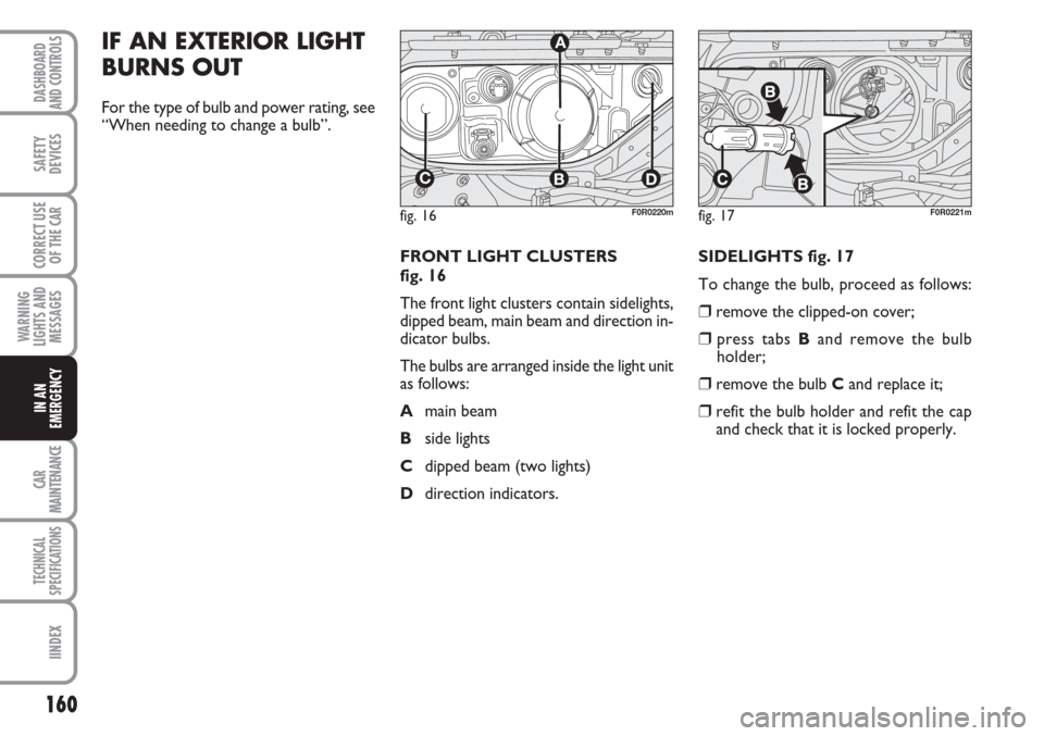
FRONT LIGHT CLUSTERS
fig. 16
The front light clusters contain sidelights,
dipped beam, main beam and direction in-
dicator bulbs.
The bulbs are arranged inside the light unit
as follows:
Amain beam
Bside lights
Cdipped beam (two lights)
Ddirection indicators. SIDELIGHTS fig. 17
To change the bulb, proceed as follows:
❒remove the clipped-on cover;
❒press tabs Band remove the bulb
holder;
❒remove the bulb Cand replace it;
❒refit the bulb holder and refit the cap
and check that it is locked properly.
fig. 16
CBD
A
F0R0220mfig. 17F0R0221m
Page 162 of 230
161
WARNING
LIGHTS AND
MESSAGES
CAR
MAINTENANCE
TECHNICAL
SPECIFICATIONS
INDEX
DASHBOARD
AND CONTROLS
SAFETY
DEVICES
CORRECT USE
OF THE
CAR
IN AN
EMERGENCY
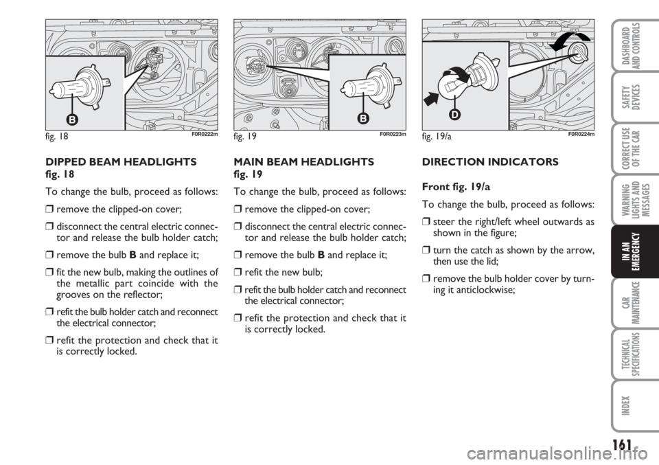
DIPPED BEAM HEADLIGHTS
fig. 18
To change the bulb, proceed as follows:
❒remove the clipped-on cover;
❒disconnect the central electric connec-
tor and release the bulb holder catch;
❒remove the bulb Band replace it;
❒fit the new bulb, making the outlines of
the metallic part coincide with the
grooves on the reflector;
❒refit the bulb holder catch and reconnect
the electrical connector;
❒refit the protection and check that it
is correctly locked.MAIN BEAM HEADLIGHTS
fig. 19
To change the bulb, proceed as follows:
❒remove the clipped-on cover;
❒disconnect the central electric connec-
tor and release the bulb holder catch;
❒remove the bulb Band replace it;
❒refit the new bulb;
❒refit the bulb holder catch and reconnect
the electrical connector;
❒refit the protection and check that it
is correctly locked.DIRECTION INDICATORS
Front fig. 19/a
To change the bulb, proceed as follows:
❒steer the right/left wheel outwards as
shown in the figure;
❒turn the catch as shown by the arrow,
then use the lid;
❒remove the bulb holder cover by turn-
ing it anticlockwise;
fig. 18F0R0222mfig. 19/aF0R0224mfig. 19F0R0223m
Page 163 of 230
162
WARNING
LIGHTS AND
MESSAGES
CAR
MAINTENANCE
TECHNICAL
SPECIFICATIONS
IINDEX
DASHBOARD
AND CONTROLS
SAFETY
DEVICES
CORRECT USE
OF THE
CAR
IN AN
EMERGENCY
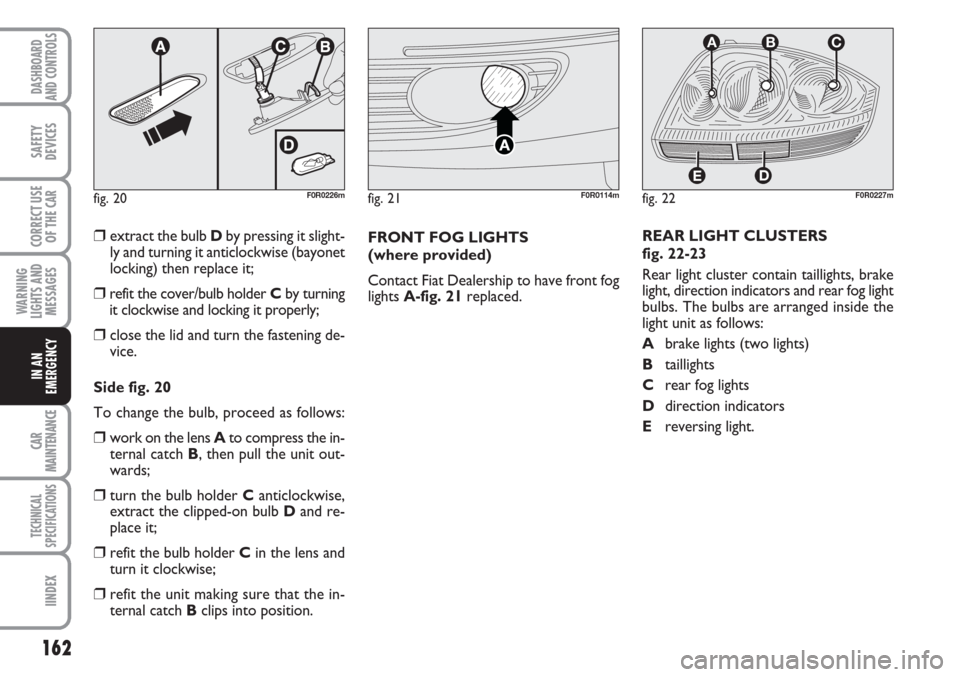
❒extract the bulb Dby pressing it slight-
ly and turning it anticlockwise (bayonet
locking) then replace it;
❒refit the cover/bulb holder Cby turning
it clockwise and locking it properly;
❒close the lid and turn the fastening de-
vice.
Side fig. 20
To change the bulb, proceed as follows:
❒work on the lens Ato compress the in-
ternal catch B, then pull the unit out-
wards;
❒turn the bulb holder Canticlockwise,
extract the clipped-on bulb Dand re-
place it;
❒refit the bulb holder Cin the lens and
turn it clockwise;
❒refit the unit making sure that the in-
ternal catch Bclips into position.FRONT FOG LIGHTS
(where provided)
Contact Fiat Dealership to have front fog
lights A-fig. 21replaced.REAR LIGHT CLUSTERS
fig. 22-23
Rear light cluster contain taillights, brake
light, direction indicators and rear fog light
bulbs. The bulbs are arranged inside the
light unit as follows:
Abrake lights (two lights)
Btaillights
Crear fog lights
Ddirection indicators
Ereversing light.
fig. 20F0R0226mfig. 22
D
ABC
E
F0R0227mfig. 21F0R0114m
Page 164 of 230
163
WARNING
LIGHTS AND
MESSAGES
CAR
MAINTENANCE
TECHNICAL
SPECIFICATIONS
INDEX
DASHBOARD
AND CONTROLS
SAFETY
DEVICES
CORRECT USE
OF THE
CAR
IN AN
EMERGENCY
fig. 23/aF0R0228m
fig. 24F0R0230m
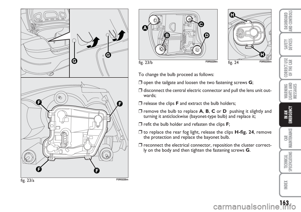
To change the bulb proceed as follows:
❒open the tailgate and loosen the two fastening screws G;
❒disconnect the central electric connector and pull the lens unit out-
wards;
❒release the clips Fand extract the bulb holders;
❒remove the bulb to replace A, B, Cor D pushing it slightly and
turning it anticlockwise (bayonet-type bulb) and replace it;
❒refit the bulb holder and refasten the clips F;
❒to replace the rear fog light, release the clips H-fig. 24, remove
the protection and replace the bayonet bulb.
❒reconnect the electrical connector, reposition the cluster correct-
ly on the body and then tighten the fastening screws G.
fig. 23/bF0R0229m