Engine light FIAT LINEA 2007 1.G User Guide
[x] Cancel search | Manufacturer: FIAT, Model Year: 2007, Model line: LINEA, Model: FIAT LINEA 2007 1.GPages: 230, PDF Size: 3.31 MB
Page 43 of 230
42
SAFETY
DEVICES
CORRECT USE
OF THE
CAR
WARNING
LIGHTS AND
MESSAGES
IN AN
EMERGENCY
CAR
MAINTENANCE
TECHNICAL
SPECIFICATIONS
INDEX
DASHBOARD
AND CONTROLS
TRIP COMPUTER
General features
The “Trip computer” is used to display in-
formation on car operation when the key
is turned to MAR. This function allows to
define two separate trips called “Trip A”
and “Trip B” for monitoring the car’s
“complete mission” in a reciprocally in-
dependent manner.
Both functions are resettable (reset - start
of new mission).
“Trip A” may be used to display the fig-
ures relating to:
– Range
– Distance travelled
– Average consumption
– Instant consumption
– Average speed
– Travel time (driving time).“Trip B”, available on multifunctional dis-
play only, shall be used to display the fig-
ures relating to:
– Trip distance B
– Average consumption B
– Average speed B
– Travel time B (driving time).
Note“Trip B” functions may be exclud-
ed (see “Trip B on”). “Range” and “In-
stantaneous consumption” cannot be re-
set.Values displayed
Range
This indicates the distance which may be
travelled with the fuel in the tank
assuming that driving conditions will not
change. The message “——” will appear
on the display in the following cases:
– range shorter than 50 km (or 30 mi)
– car left parked with engine running for
long.
Distance travelled
This indicates the distance covered from
the start of the new mission.
Page 44 of 230
43
SAFETY
DEVICES
CORRECT USE
OF THE
CAR
WARNING
LIGHTS AND
MESSAGES
IN AN
EMERGENCY
CAR
MAINTENANCE
TECHNICAL
SPECIFICATIONS
INDEX
DASHBOARD
AND CONTROLS
Average consumption
This indicates the average consumption
from the start of the new mission.
Instant consumption
This indicates the fuel consumption. The
value is constantly updated. The message
“----” will appear on the display
if the car is parked with the engine run-
ning.
Average speed
This shows the car average speed as a
function of the overall time elapsed since
the start of the new mission.
Travel time
This value shows the time elapsed since
the start of the new mission.
IMPORTANT If information is not avail-
able, the message “----” will appear instead
of the Trip Computer values. Displaying
of the values will be resumed when nor-
mal operation is restored without reset-
ting the values displayed before the prob-
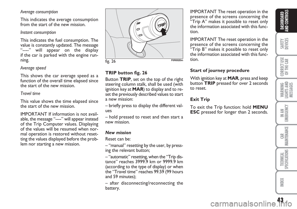
lem nor starting a new mission. TRIP button fig. 26
Button TRIP, set on the top of the right
steering column stalk, shall be used (with
ignition key at MAR) to display and to re-
set the previously described values to start
a new mission:
– briefly press to display the different val-
ues
– hold pressed to reset and then start a
new mission.
New mission
Reset can be:
– “manual” resetting by the user, by press-
ing the relevant button;
– “automatic” resetting, when the “Trip dis-
tance” reaches 3999.9 km or 9999.9 km
(according to the type of display) or when
the “Travel time” reaches 99.59 (99 hours
and 59 minutes);
– after disconnecting/reconnecting the
battery.IMPORTANT The reset operation in the
presence of the screens concerning the
“Trip A” makes it possible to reset only
the information associated with this func-
tion.
IMPORTANT The reset operation in the
presence of the screens concerning the
“Trip B” makes it possible to reset only
the information associated with this func-
tion.
Start of journey procedure
With ignition key at MAR, press and keep
button TRIPpressed for over 2 seconds
to reset.
Exit Trip
To exit the Trip function: hold MENU
ESCpressed for longer than 2 seconds.
fig. 26F0R0020m
Page 48 of 230
47
SAFETY
DEVICES
CORRECT USE
OF THE
CAR
WARNING
LIGHTS AND
MESSAGES
IN AN
EMERGENCY
CAR
MAINTENANCE
TECHNICAL
SPECIFICATIONS
INDEX
DASHBOARD
AND CONTROLS
REARVIEW MIRRORS
DRIVING MIRROR fig. 32
The mirror is fitted with a safety device
that causes it to be released in the event
of a violent crash.
STEERING WHEEL
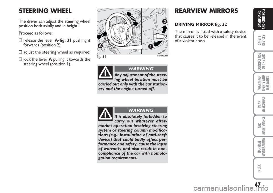
The driver can adjust the steering wheel
position both axially and in height.
Proceed as follows:
❒release the lever A-fig. 31pushing it
forwards (position 2);
❒adjust the steering wheel as required;
❒lock the lever Apulling it towards the
steering wheel (position 1).fig. 31F0R0026m
Any adjustment of the steer-
ing wheel position must be
carried out only with the car station-
ary and the engine turned off.
WARNING
It is absolutely forbidden to
carry out whatever after-
market operation involving steering
system or steering column modifica-
tions (e.g.: installation of anti-theft
device) that could badly affect per-
formance and safety, cause the lapse
of warranty and also result in non-
compliance of the car with homolo-
gation requirements.
WARNING
Page 52 of 230
51
SAFETY
DEVICES
CORRECT USE
OF THE
CAR
WARNING
LIGHTS AND
MESSAGES
IN AN
EMERGENCY
CAR
MAINTENANCE
TECHNICAL
SPECIFICATIONS
INDEX
DASHBOARD
AND CONTROLS
Air distribution knob C
¶to convey air to the central and side
vents;
ßto warm the feet and convey cooler
air to the dashboard vents, in inter-
mediate temperature conditions;
©for heating when the outside temper-
ature is very cold: for maximum air
flow to feet;
®to warm the feet and demist the wind-
screen at the same time;
-for quick windscreen demisting.
Air recirculation on/off slider D
Take the slider to position
vto re-
circulate internal air.
Take the slider to position
¶to switch
internal air recirculation off.FAST HEATING
For fast heating of the passenger com-
partment, proceed as follows:
❒turn knob Ato the red sector;
❒switch internal air recirculation on;
❒turn knob Cto ¶;
❒knob Bturned to 4 -(max. fan
speed).
Then use the controls to keep the re-
quired comfort conditions and press but-
ton Dto
¶to turn air recirculation off
(button led off) and to prevent misting up.
IMPORTANT With cold engine, you have
to wait for a few minutes to let the sys-
tem fluid reach the operating temperature. VENTILATION
To ventilate the passenger’s compartment
properly proceed as follows:
❒knob Aturned to blue section;
❒switch internal air recirculation off;
❒turn knob Cto ¶;
❒turn knob Bto required speed.
WARMING THE PASSENGER
COMPARTMENT
Proceed as follows:
❒turn knob Ato the red sector;
❒turn knob Cto the required position;
❒turn knob Bto required speed.
Page 57 of 230
56
SAFETY
DEVICES
CORRECT USE
OF THE
CAR
WARNING
LIGHTS AND
MESSAGES
IN AN
EMERGENCY
CAR
MAINTENANCE
TECHNICAL
SPECIFICATIONS
INDEX
DASHBOARD
AND CONTROLS
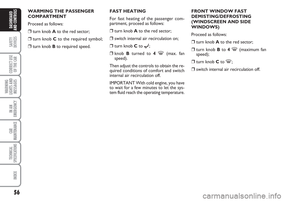
WARMING THE PASSENGER
COMPARTMENT
Proceed as follows:
❒turn knob Ato the red sector;
❒turn knob Cto the required symbol;
❒turn knob Bto required speed.FAST HEATING
For fast heating of the passenger com-
partment, proceed as follows:
❒turn knob Ato the red sector;
❒switch internal air recirculation on;
❒turn knob Cto ©;
❒knob Bturned to 4-(max. fan
speed).
Then adjust the controls to obtain the re-
quired conditions of comfort and switch
internal air recirculation off.
IMPORTANT With cold engine, you have
to wait for a few minutes to let the sys-
tem fluid reach the operating temperature.FRONT WINDOW FAST
DEMISTING/DEFROSTING
(WINDSCREEN AND SIDE
WINDOWS)
Proceed as follows:
❒turn knob Ato the red sector;
❒turn knob Bto 4-(maximum fan
speed);
❒turn knob Cto -;
❒switch internal air recirculation off.
Page 65 of 230
64
SAFETY
DEVICES
CORRECT USE
OF THE
CAR
WARNING
LIGHTS AND
MESSAGES
IN AN
EMERGENCY
CAR
MAINTENANCE
TECHNICAL
SPECIFICATIONS
INDEX
DASHBOARD
AND CONTROLS
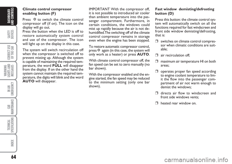
Climate control compressor
enabling button (F)
Press √to switch the climate control
compressor off (if on). The icon on the
display will go out.
Press the button when the LED is off to
restore automatically system control
and use of the compressor. The icon
will light up on the display in this case.
The system will switch recirculation off
when the compressor is switched off to
prevent misting up. Although the system
is capable of maintaining the required tem-
perature, the word FULLwill disappear
from the display. If on the other hand the
system cannot maintain the required tem-
perature, the digits will blink and the word
AUTOwill disappear.IMPORTANT With the compressor off,
it is not possible to introduced air cooler
than ambient temperature into the pas-
senger compartment. Furthermore, in
certain conditions, the windows could
mist up rapidly because the air is not de-
humidified.The switching off of the climate
control compressor remains in storage
even when the engine has been stopped.
To restore automatic compressor control,
press √again (in this case, the system will
only work as a heater) or press AUTO.
With climate control compressor off, the
fan speed can be set to zero manually (no
bar shown).
With the compressor enabled and the en-
gine started, the fan speed may be reduced
to the minimum setting (only one bar
shown).Fast window demisting/defrosting
button (D)
Press this button: the climate control sys-
tem will automatically switch on all the
functions required for fast windscreen and
front side window demisting/defrosting,
that is:
❒switches on climate control compres-
sor when climatic conditions are suit-
able;
❒air recirculation off;
❒maximum air temperature HI on both
areas;
❒operates proper fan speed according
to engine coolant temperature to lim-
it the flow into the passenger com-
partment of air not warm enough to
demist the windows;
❒directs air flow to windscreen and
front side windows vents;
❒heated rear window on.
Page 66 of 230
65
SAFETY
DEVICES
CORRECT USE
OF THE
CAR
WARNING
LIGHTS AND
MESSAGES
IN AN
EMERGENCY
CAR
MAINTENANCE
TECHNICAL
SPECIFICATIONS
INDEX
DASHBOARD
AND CONTROLS
IMPORTANT The quick demisting/de-
frosting function will stay on for approxi-
mately 3 minutes after the engine coolant
temperature is warm enough to ensure
rapid window demisting.
When the function is on, the LED on the
rear window demister button will light up
and the message FULL AUTOwill go
out on the display.
You may only adjust the fan speed and
switch the rear window demister off man-
ually when this function is running.
To restore running operations before this
function was activated, press either but-
ton B, air recirculation button G, com-
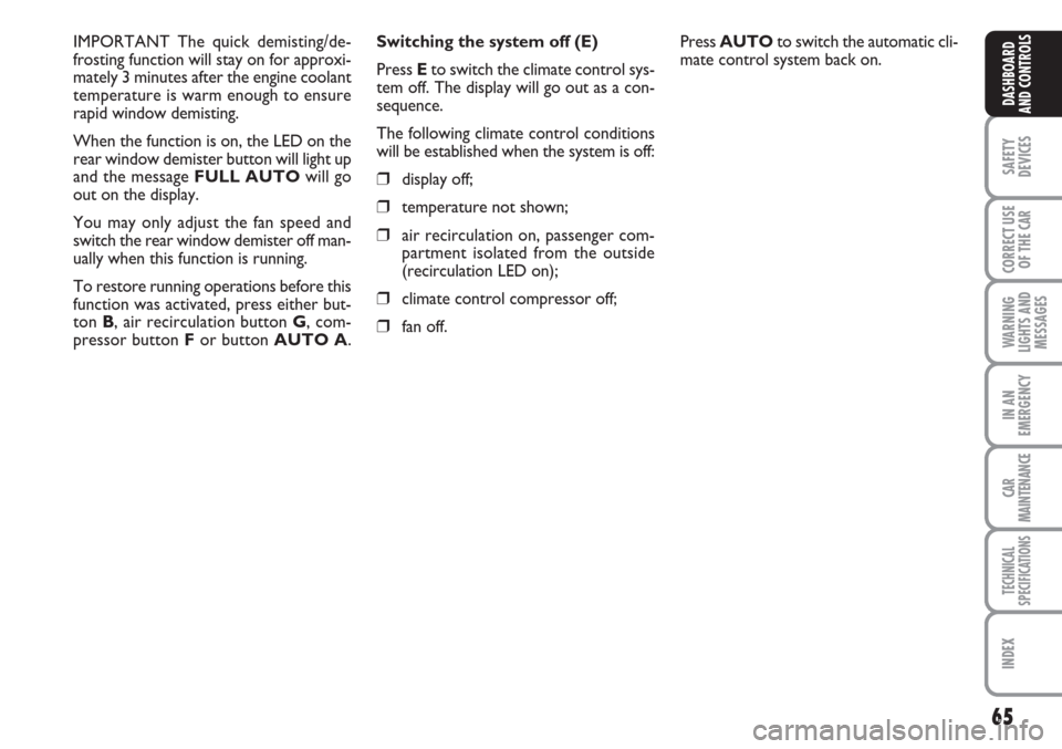
pressor button For button AUTO A.Switching the system off (E)
Press Eto switch the climate control sys-
tem off. The display will go out as a con-
sequence.
The following climate control conditions
will be established when the system is off:
❒display off;
❒temperature not shown;
❒air recirculation on, passenger com-
partment isolated from the outside
(recirculation LED on);
❒climate control compressor off;
❒fan off.Press AUTOto switch the automatic cli-
mate control system back on.
Page 68 of 230
67
SAFETY
DEVICES
CORRECT USE
OF THE
CAR
WARNING
LIGHTS AND
MESSAGES
IN AN
EMERGENCY
CAR
MAINTENANCE
TECHNICAL
SPECIFICATIONS
INDEX
DASHBOARD
AND CONTROLS
Deactivation
The main beam headlights will go out fol-
lowed after approximately 10 seconds by
the side/taillights when the sensor is de-
activated.
The sensor cannot detect the presence of
fog: switch the lights on manually in this
case.
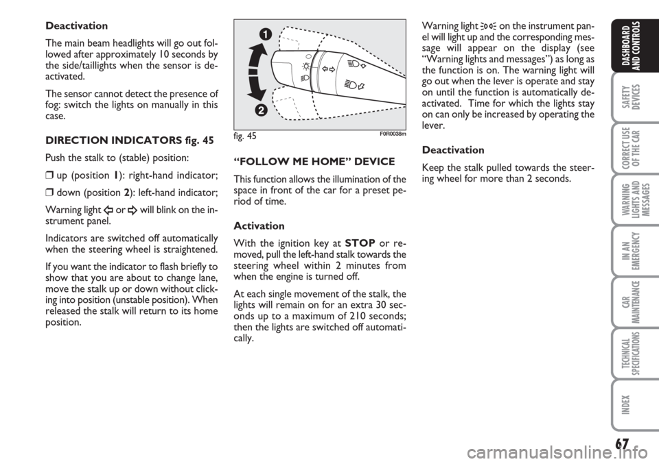
DIRECTION INDICATORS fig. 45
Push the stalk to (stable) position:
❒up (position 1): right-hand indicator;
❒down (position 2): left-hand indicator;
Warning light
Îor ¥will blink on the in-
strument panel.
Indicators are switched off automatically
when the steering wheel is straightened.
If you want the indicator to flash briefly to
show that you are about to change lane,
move the stalk up or down without click-
ing into position (unstable position). When
released the stalk will return to its home
position.“FOLLOW ME HOME” DEVICE
This function allows the illumination of the
space in front of the car for a preset pe-
riod of time.
Activation
With the ignition key at STOPor re-
moved, pull the left-hand stalk towards the
steering wheel within 2 minutes from
when the engine is turned off.
At each single movement of the stalk, the
lights will remain on for an extra 30 sec-
onds up to a maximum of 210 seconds;
then the lights are switched off automati-
cally. Warning light
3on the instrument pan-
el will light up and the corresponding mes-
sage will appear on the display (see
“Warning lights and messages”) as long as
the function is on. The warning light will
go out when the lever is operate and stay
on until the function is automatically de-
activated. Time for which the lights stay
on can only be increased by operating the
lever.
Deactivation
Keep the stalk pulled towards the steer-
ing wheel for more than 2 seconds.
fig. 45F0R0038m
Page 69 of 230
68
SAFETY
DEVICES
CORRECT USE
OF THE
CAR
WARNING
LIGHTS AND
MESSAGES
IN AN
EMERGENCY
CAR
MAINTENANCE
TECHNICAL
SPECIFICATIONS
INDEX
DASHBOARD
AND CONTROLS
WINDOW WASHING
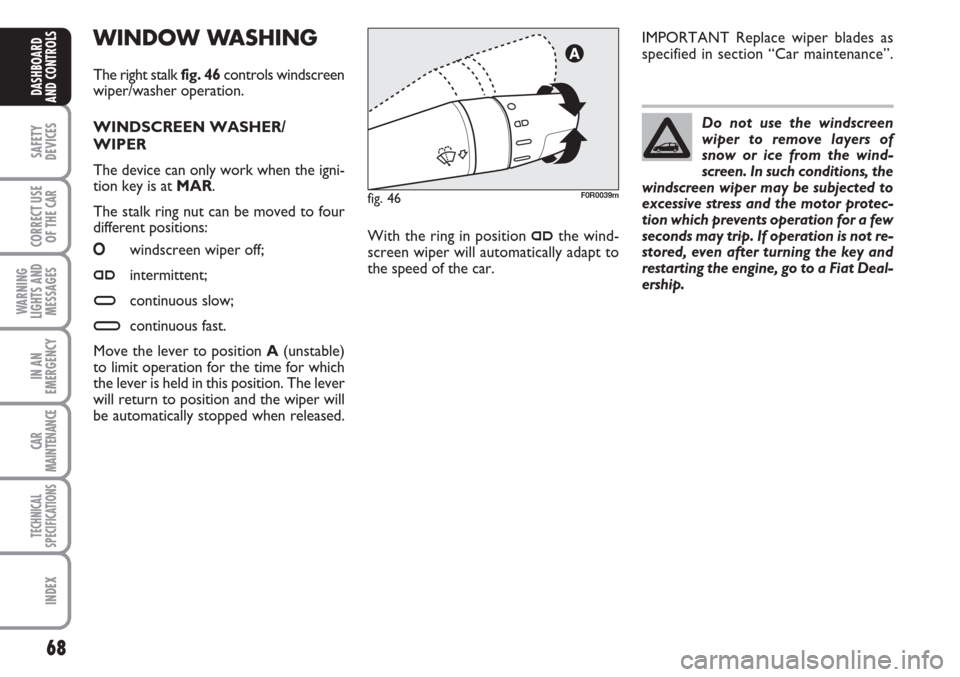
The right stalk fig. 46controls windscreen
wiper/washer operation.
WINDSCREEN WASHER/
WIPER
The device can only work when the igni-
tion key is at MAR.
The stalk ring nut can be moved to four
different positions:
Owindscreen wiper off;
≤intermittent;
≥continuous slow;
¥continuous fast.
Move the lever to position A(unstable)
to limit operation for the time for which
the lever is held in this position. The lever
will return to position and the wiper will
be automatically stopped when released.Do not use the windscreen
wiper to remove layers of
snow or ice from the wind-
screen. In such conditions, the
windscreen wiper may be subjected to
excessive stress and the motor protec-
tion which prevents operation for a few
seconds may trip. If operation is not re-
stored, even after turning the key and
restarting the engine, go to a Fiat Deal-
ership.
With the ring in position
≤the wind-
screen wiper will automatically adapt to
the speed of the car.IMPORTANT Replace wiper blades as
specified in section “Car maintenance”.
fig. 46F0R0039m
Page 72 of 230
71
SAFETY
DEVICES
CORRECT USE
OF THE
CAR
WARNING
LIGHTS AND
MESSAGES
IN AN
EMERGENCY
CAR
MAINTENANCE
TECHNICAL
SPECIFICATIONS
INDEX
DASHBOARD
AND CONTROLS
RESTORING STORED SPEED
If the device has been disengaged for ex-
ample pressing the brake or clutch pedal,
the memorised speed can be reset as fol-
lows:
❒accelerate gradually until reaching a
speed approaching the one stored;
❒engage the gear selected at the time
when the speed was originally stored;
❒press RES B-fig. 47.
INCREASING THE STORED
SPEED
The stored speed can be increased in two
ways:
❒by pressing the accelerator and then
storing the new speed reached;
or
❒by moving the stalk upwards (+).
Each operation of the stalk will corre-
spond to a slight increase in speed (about
1 km/h), while keeping the stalk upwards
will correspond to a continuous speed in-
crease. REDUCING THE STORED SPEED
The stored speed can be increased in two
ways:
❒by switching the device off and then
storing a new speed;
or
❒by moving the stalk downwards (–) un-
til reaching the new speed which will be
stored automatically.
Each operation of the stalk will corre-
spond to a slight reduction in speed (about
1 km/h), while keeping the stalk down-
wards will correspond to a continuous
speed reduction.
SWITCHING THE DEVICE OFF
The device can be switch off in the fol-
lowing ways:
❒by turning knob Ato OFF;
❒by turning the engine off;
❒by pressing the brake pedal;
❒by pressing the clutch pedal;
❒by pressing the accelerator pedal; in this
case the system is not really switched
off but the request for acceleration
takes priority over the system. The
cruise control is however active and it
will not be necessary to press button
RES B-fig. 47to resume previous con-
ditions after ending acceleration.
The device is automatically switched off in
one of the following cases:
❒if the ABSor ESPsystems cut-in;
❒with car speed below the preset limit;
❒in the case of system failure.
When travelling with the de-
vice on, never set the
gearshift lever to neutral.
WARNING
In the event of device faults
or failures, turn knob A to
OFF and contact a Fiat Dealership.
WARNING