Engine light FIAT LINEA 2007 1.G Workshop Manual
[x] Cancel search | Manufacturer: FIAT, Model Year: 2007, Model line: LINEA, Model: FIAT LINEA 2007 1.GPages: 230, PDF Size: 3.31 MB
Page 148 of 230
147
WARNING
LIGHTS AND
MESSAGES
CAR
MAINTENANCE
TECHNICAL
SPECIFICATIONS
INDEX
DASHBOARD
AND CONTROLS
SAFETY
DEVICES
CORRECT USE
OF THE
CAR
IN AN
EMERGENCY
IMPORTANT Never connect the negative
terminals of the two batteries directly:
sparks could ignite explosive gas released
from the battery. If the auxiliary battery is
installed on another car, prevent acciden-
tal contact between metallic parts of the
two cars.BUMP STARTING
Never jump start the engine by pushing,
towing or driving downhill. This could
cause a flow of fuel into the catalytic con-
verter and damage it beyond repair.
IMPORTANT Remember that the brake
booster and the power steering system
are not operating until the engine is start-
ed, a greater effort will therefore be re-
quired to press the brake pedal or turn
the steering wheel.REPLACING A WHEEL
GENERAL INSTRUCTIONS
Wheel changing and correct use of the
jack and spare wheel call for some pre-
cautions as listed below.
Indicate that the car is sta-
tionary according to the laws
in force: hazard lights, triangle, etc.
Passengers should leave the car, par-
ticularly if it is very loaded and wait
for the wheel to be changed away
from on-coming traffic. Apply the
handbrake.
WARNING
Page 150 of 230
149
WARNING
LIGHTS AND
MESSAGES
CAR
MAINTENANCE
TECHNICAL
SPECIFICATIONS
INDEX
DASHBOARD
AND CONTROLS
SAFETY
DEVICES
CORRECT USE
OF THE
CAR
IN AN
EMERGENCY
To change a wheel proceed as
follows:
❒stop the car in a position so that it is
not a danger for on-coming traffic and
where you can replace the wheel safe-
ly. The ground must be flat and com-
pact;
❒stop the engine off and pull up the hand-
brake;
❒engage first gear or reverse;
❒wear the reflecting safety jacket (com-
pulsory by law in certain countries) be-
fore getting out of the car;
❒open the tailgate and lift the mat;
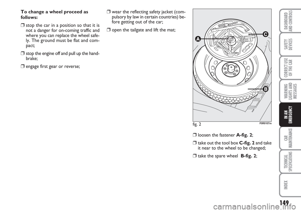
❒loosen the fastener A-fig. 2;
❒take out the tool box C-fig. 2and take
it near to the wheel to be changed;
❒take the spare wheel B-fig. 2;
fig. 2F0R0107m
Page 157 of 230
156
WARNING
LIGHTS AND
MESSAGES
CAR
MAINTENANCE
TECHNICAL
SPECIFICATIONS
IINDEX
DASHBOARD
AND CONTROLS
SAFETY
DEVICES
CORRECT USE
OF THE
CAR
IN AN
EMERGENCY
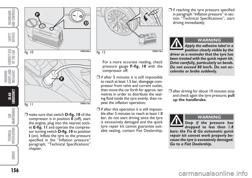
❒make sure that switch D-fig. 10of the
compressor is in position 0(off), start
the engine, plug into the nearest sock-
et E-fig. 11and operate the compres-
sor turning switch D-fig. 10to position
I(on). Inflate the tyre to the pressure
specified in the “Inflation pressure”
paragraph, “Technical Specifications”
chapter. For a more accurate reading, check
pressure gauge F-fig. 10with the
compressor off;
❒if after 5 minutes it is still impossible
to reach at least 1.5 bar, disengage com-
pressor from valve and current outlet,
then move the car forth for approx. ten
metres in order to distribute the seal-
ing fluid inside the tyre evenly, then re-
peat the inflation operation;
❒If after this operation it is still impossi-
ble after 5 minutes to reach at least 1.8
bar, do not start driving since the tyre
is excessively damaged and the quick
tyre repair kit cannot guarantee suit-
able sealing, contact Fiat Dealership;
❒if reaching the tyre pressure specified
in paragraph “Inflation pressure” in sec-
tion “Technical Specifications”, start
driving immediately;
fig. 10F0R0160m
fig. 11F0R0113m
fig. 12F0R0110m
Apply the adhesive label in a
position clearly visible by the
driver as a reminder that the tyre has
been treated with the quick repair kit.
Drive carefully, particularly on bends.
Do not exceed 80 km/h. Do not ac-
celerate or brake suddenly.
WARNING
❒after driving for about 10 minutes stop
and check again the tyre pressure; pull
up the handbrake;
Stop if the pressure has
dropped to less than 1.8
bars: the Fix & Go automatic quick
repair kit cannot work properly be-
cause the tyre is excessively damaged.
Go to a Fiat Dealership.
WARNING
Page 158 of 230
157
WARNING
LIGHTS AND
MESSAGES
CAR
MAINTENANCE
TECHNICAL
SPECIFICATIONS
INDEX
DASHBOARD
AND CONTROLS
SAFETY
DEVICES
CORRECT USE
OF THE
CAR
IN AN
EMERGENCY
❒if at least 1.8 bar pressure is read, re-
store proper pressure (with engine
running and handbrake on) and restart;
❒drive with the utmost care to the near-
est Fiat Dealership.
FOR CHECKING AND
RESTORING PRESSURE ONLY
The compressor may also be used for
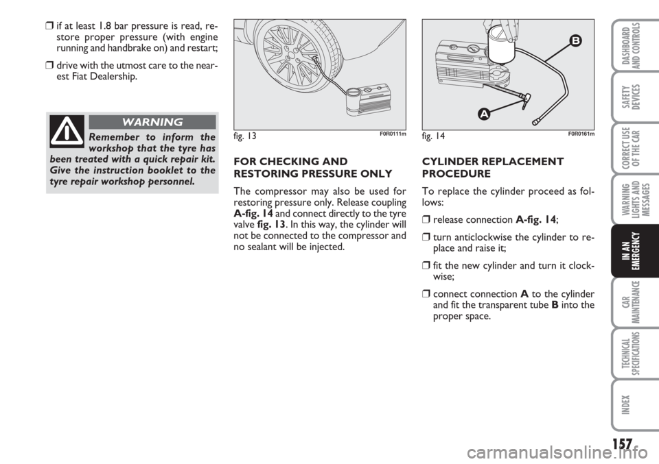
restoring pressure only. Release coupling
A-fig. 14and connect directly to the tyre
valve fig. 13. In this way, the cylinder will
not be connected to the compressor and
no sealant will be injected. CYLINDER REPLACEMENT
PROCEDURE
To replace the cylinder proceed as fol-
lows:
❒release connection A-fig. 14;
❒turn anticlockwise the cylinder to re-
place and raise it;
❒fit the new cylinder and turn it clock-
wise;
❒connect connection Ato the cylinder
and fit the transparent tube Binto the
proper space.
Remember to inform the
workshop that the tyre has
been treated with a quick repair kit.
Give the instruction booklet to the
tyre repair workshop personnel.
WARNING
fig. 13F0R0111mfig. 14F0R0161m
Page 169 of 230
168
WARNING
LIGHTS AND
MESSAGES
CAR
MAINTENANCE
TECHNICAL
SPECIFICATIONS
IINDEX
DASHBOARD
AND CONTROLS
SAFETY
DEVICES
CORRECT USE
OF THE
CAR
IN AN
EMERGENCY
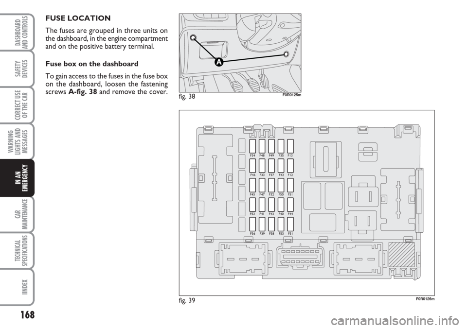
FUSE LOCATION
The fuses are grouped in three units on
the dashboard, in the engine compartment
and on the positive battery terminal.
Fuse box on the dashboard
To gain access to the fuses in the fuse box
on the dashboard, loosen the fastening
screws A-fig. 38and remove the cover.
fig. 39F0R0126m
F34 F48 F49 F35 F13
F46 F33 F37 F42 F12
F45 F47 F32 F50 F51
F52 F41 F43 F40 F44
F36 F39 F38 F53 F31
fig. 38F0R0125m
Page 170 of 230
169
WARNING
LIGHTS AND
MESSAGES
CAR
MAINTENANCE
TECHNICAL
SPECIFICATIONS
INDEX
DASHBOARD
AND CONTROLS
SAFETY
DEVICES
CORRECT USE
OF THE
CAR
IN AN
EMERGENCY
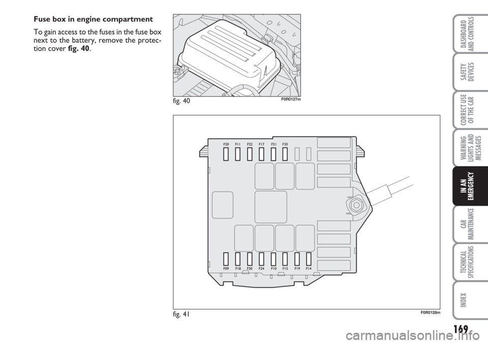
Fuse box in engine compartment
To gain access to the fuses in the fuse box
next to the battery, remove the protec-
tion cover fig. 40.
fig. 40F0R0127m
fig. 41F0R0128m
Page 171 of 230
170
WARNING
LIGHTS AND
MESSAGES
CAR
MAINTENANCE
TECHNICAL
SPECIFICATIONS
IINDEX
DASHBOARD
AND CONTROLS
SAFETY
DEVICES
CORRECT USE
OF THE
CAR
IN AN
EMERGENCY
7.5
7.5
7.5
15
20
20
7.5
7.5
7.5
20
10
30
7.5
7.5
20 F12
F13
F31
F32
F33
F34
F35
F36
F37
F38
F39
F40
F41
F42
F43
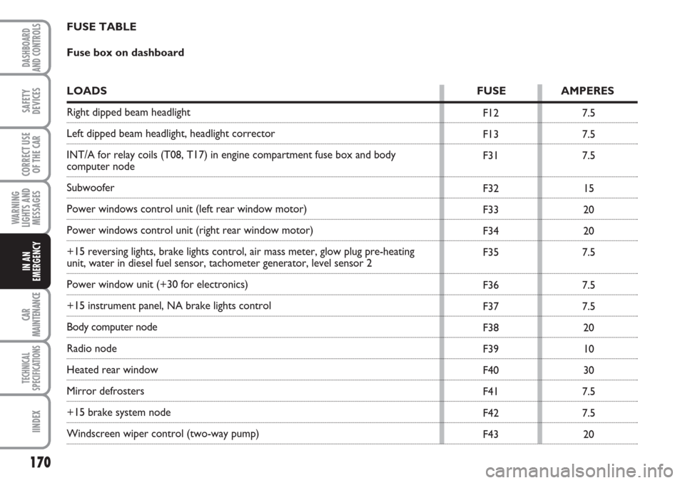
FUSE TABLE
Fuse box on dashboard
LOADS FUSE AMPERES
Right dipped beam headlight
Left dipped beam headlight, headlight corrector
INT/A for relay coils (T08, T17) in engine compartment fuse box and body
computer node
Subwoofer
Power windows control unit (left rear window motor)
Power windows control unit (right rear window motor)
+15 reversing lights, brake lights control, air mass meter, glow plug pre-heating
unit, water in diesel fuel sensor, tachometer generator, level sensor 2
Power window unit (+30 for electronics)
+15 instrument panel, NA brake lights control
Body computer node
Radio node
Heated rear window
Mirror defrosters
+15 brake system node
Windscreen wiper control (two-way pump)
Page 173 of 230
172
WARNING
LIGHTS AND
MESSAGES
CAR
MAINTENANCE
TECHNICAL
SPECIFICATIONS
IINDEX
DASHBOARD
AND CONTROLS
SAFETY
DEVICES
CORRECT USE
OF THE
CAR
IN AN
EMERGENCY
20
30
40
20
40
30
15
10
7.5
7.5
10
10
7.5 F03
F04
F05
F06
F07
F08
F10
F11
F14
F15
F17
F18
F19
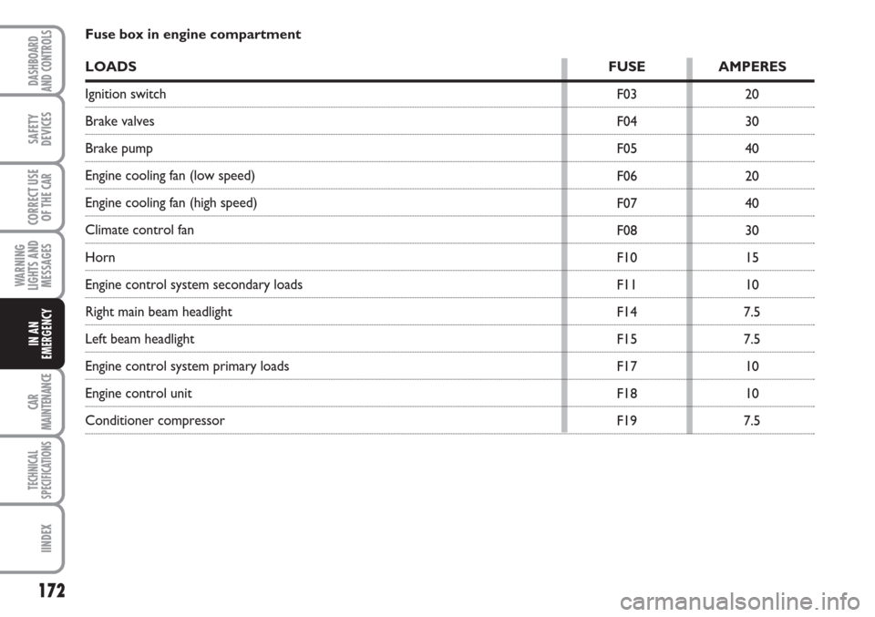
Fuse box in engine compartment
LOADS FUSE AMPERES
Ignition switch
Brake valves
Brake pump
Engine cooling fan (low speed)
Engine cooling fan (high speed)
Climate control fan
Horn
Engine control system secondary loads
Right main beam headlight
Left beam headlight
Engine control system primary loads
Engine control unit
Conditioner compressor
Page 174 of 230
173
WARNING
LIGHTS AND
MESSAGES
CAR
MAINTENANCE
TECHNICAL
SPECIFICATIONS
INDEX
DASHBOARD
AND CONTROLS
SAFETY
DEVICES
CORRECT USE
OF THE
CAR
IN AN
EMERGENCY
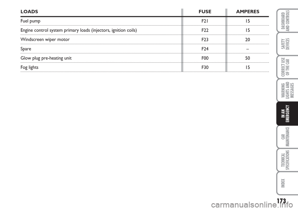
15
15
20
–
50
15 F21
F22
F23
F24
F00
F30
LOADSFUSE AMPERES
Fuel pump
Engine control system primary loads (injectors, ignition coils)
Windscreen wiper motor
Spare
Glow plug pre-heating unit
Fog lights
Page 177 of 230
176
WARNING
LIGHTS AND
MESSAGES
CAR
MAINTENANCE
TECHNICAL
SPECIFICATIONS
IINDEX
DASHBOARD
AND CONTROLS
SAFETY
DEVICES
CORRECT USE
OF THE
CAR
IN AN
EMERGENCY
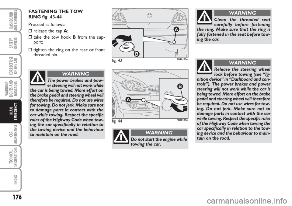
FASTENING THE TOW
RING fig. 43-44
Proceed as follows:
❒release the cap A;
❒take the tow hook Bfrom the sup-
port;
❒tighten the ring on the rear or front
threaded pin.
The power brakes and pow-
er steering will not work while
the car is being towed. More effort on
the brake pedal and steering wheel will
therefore be required. Do not use wires
for towing. Do not jerk. Make sure not
to damage parts in contact with the
car while towing. Respect the specific
rules of the Highway Code when tow-
ing the car specifically in relation to
the towing device and the behaviour
to maintain on the road.
WARNING
fig. 43F0R0130m
fig. 44F0R0131m
Do not start the engine while
towing the car.
WARNING
Clean the threaded seat
carefully before fastening
the ring. Make sure that the ring is
fully fastened in the seat before tow-
ing the car.
WARNING
Release the steering wheel
lock before towing (see “Ig-
nition device” in “Dashboard and con-
trols”). The power brakes and power
steering will not work while the car is
being towed. More effort on the brake
pedal and steering wheel will therefore
be required. Do not use wires for tow-
ing. Do not jerk. Make sure not to
damage parts in contact with the car
while towing. Respect the specific rules
of the Highway Code when towing the
car specifically in relation to the tow-
ing device and the behaviour to main-
tain on the road.
WARNING