headlight FIAT LINEA 2007 1.G User Guide
[x] Cancel search | Manufacturer: FIAT, Model Year: 2007, Model line: LINEA, Model: FIAT LINEA 2007 1.GPages: 230, PDF Size: 3.31 MB
Page 67 of 230
66
SAFETY
DEVICES
CORRECT USE
OF THE
CAR
WARNING
LIGHTS AND
MESSAGES
IN AN
EMERGENCY
CAR
MAINTENANCE
TECHNICAL
SPECIFICATIONS
INDEX
DASHBOARD
AND CONTROLS
EXTERNAL LIGHTS
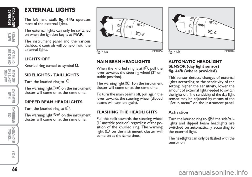
The left-hand stalk fig. 44/aoperates
most of the external lights.
The external lights can only be switched
on when the ignition key is at MAR.
The instrument panel and the various
dashboard controls will come on with the
external lights.
LIGHTS OFF
Knurled ring turned to symbol O.
SIDELIGHTS - TAILLIGHTS
Turn the knurled ring to
6.
The warning light
3on the instrument
cluster will come on at the same time.
DIPPED BEAM HEADLIGHTS
Turn the knurled ring to
2.
The warning light
3on the instrument
cluster will come on at the same time.MAIN BEAM HEADLIGHTS
When the knurled ring is at
2, pull the
lever towards the steering wheel (2ndun-
stable position).
The warning light
11on the instrument
cluster will come on at the same time.
To turn the main beams off, pull again the
lever towards the steering wheel (dipped
beams will turn on again).
FLASHING THE HEADLIGHTS
Pull the stalk towards the steering wheel
(1
stunstable position) regardless of the po-
sition of the knurled ring. The warning
light
1on the instrument cluster will
come on at the same time.AUTOMATIC HEADLIGHT
SENSOR (day light sensor)
fig. 44/b (where provided)
This sensor detects changes of external
lights according to the sensitivity of the
setting: higher the sensitivity, lower the
amount of external light needed to switch
the lights on. The sensitivity of the day light
sensor may be adjusted by means of the
“Setup menu” on the instrument panel.
Activation
Turn the knurled ring to
2A. the side/tail-
lights and dipped beam headlights are
switched on automatically according to
the external light.
The headlights can only be flashed with the
sensor on.
fig. 44/aF0R0037mfig. 44/bF0R0238m
Page 68 of 230
67
SAFETY
DEVICES
CORRECT USE
OF THE
CAR
WARNING
LIGHTS AND
MESSAGES
IN AN
EMERGENCY
CAR
MAINTENANCE
TECHNICAL
SPECIFICATIONS
INDEX
DASHBOARD
AND CONTROLS
Deactivation
The main beam headlights will go out fol-
lowed after approximately 10 seconds by
the side/taillights when the sensor is de-
activated.
The sensor cannot detect the presence of
fog: switch the lights on manually in this
case.
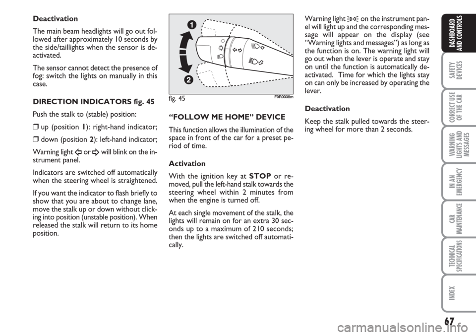
DIRECTION INDICATORS fig. 45
Push the stalk to (stable) position:
❒up (position 1): right-hand indicator;
❒down (position 2): left-hand indicator;
Warning light
Îor ¥will blink on the in-
strument panel.
Indicators are switched off automatically
when the steering wheel is straightened.
If you want the indicator to flash briefly to
show that you are about to change lane,
move the stalk up or down without click-
ing into position (unstable position). When
released the stalk will return to its home
position.“FOLLOW ME HOME” DEVICE
This function allows the illumination of the
space in front of the car for a preset pe-
riod of time.
Activation
With the ignition key at STOPor re-
moved, pull the left-hand stalk towards the
steering wheel within 2 minutes from
when the engine is turned off.
At each single movement of the stalk, the
lights will remain on for an extra 30 sec-
onds up to a maximum of 210 seconds;
then the lights are switched off automati-
cally. Warning light
3on the instrument pan-
el will light up and the corresponding mes-
sage will appear on the display (see
“Warning lights and messages”) as long as
the function is on. The warning light will
go out when the lever is operate and stay
on until the function is automatically de-
activated. Time for which the lights stay
on can only be increased by operating the
lever.
Deactivation
Keep the stalk pulled towards the steer-
ing wheel for more than 2 seconds.
fig. 45F0R0038m
Page 76 of 230
75
SAFETY
DEVICES
CORRECT USE
OF THE
CAR
WARNING
LIGHTS AND
MESSAGES
IN AN
EMERGENCY
CAR
MAINTENANCE
TECHNICAL
SPECIFICATIONS
INDEX
DASHBOARD
AND CONTROLS
CONTROLS
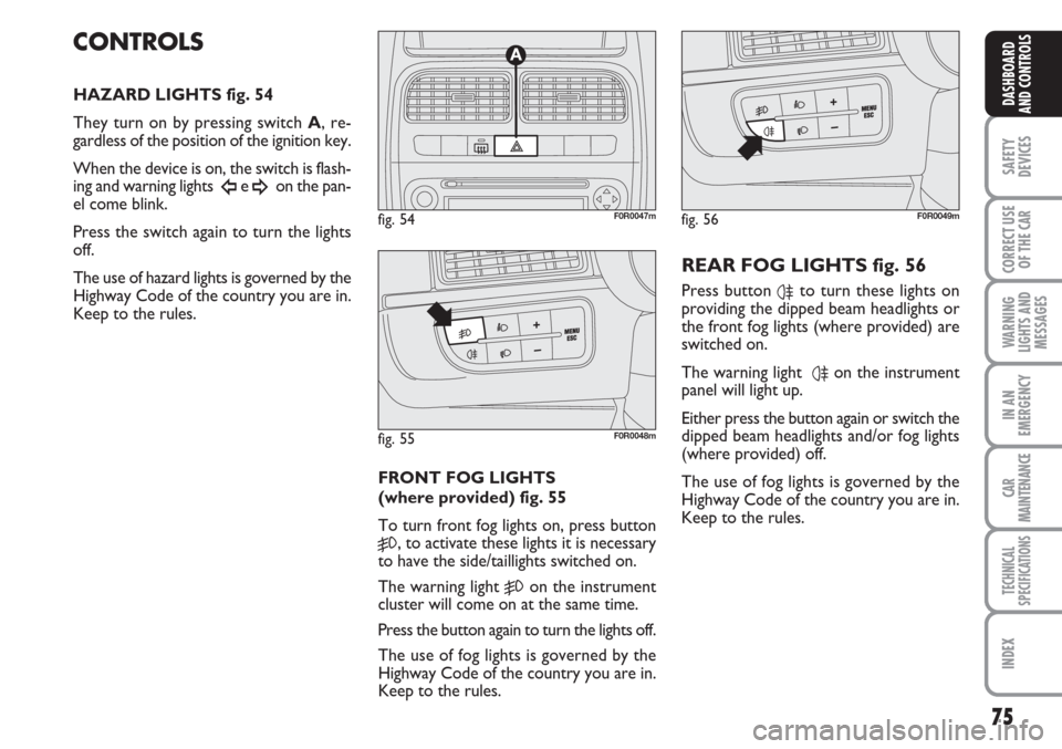
HAZARD LIGHTS fig. 54
They turn on by pressing switch A, re-
gardless of the position of the ignition key.
When the device is on, the switch is flash-
ing and warning lights
Îe ¥on the pan-
el come blink.
Press the switch again to turn the lights
off.
The use of hazard lights is governed by the
Highway Code of the country you are in.
Keep to the rules.
FRONT FOG LIGHTS
(where provided) fig. 55
To turn front fog lights on, press button
5, to activate these lights it is necessary
to have the side/taillights switched on.
The warning light
5on the instrument
cluster will come on at the same time.
Press the button again to turn the lights off.
The use of fog lights is governed by the
Highway Code of the country you are in.
Keep to the rules.
REAR FOG LIGHTS fig. 56
Press button 4to turn these lights on
providing the dipped beam headlights or
the front fog lights (where provided) are
switched on.
The warning light
4on the instrument
panel will light up.
Either press the button again or switch the
dipped beam headlights and/or fog lights
(where provided) off.
The use of fog lights is governed by the
Highway Code of the country you are in.
Keep to the rules.
fig. 54F0R0047m
fig. 55F0R0048m
fig. 56F0R0049m
Page 92 of 230
91
SAFETY
DEVICES
CORRECT USE
OF THE
CAR
WARNING
LIGHTS AND
MESSAGES
IN AN
EMERGENCY
CAR
MAINTENANCE
TECHNICAL
SPECIFICATIONS
INDEX
DASHBOARD
AND CONTROLS
HEADLIGHTS
BEAM DIRECTION
Correction direction of the headlights is
essentially for the comfort and safety of
the driver and the other road users. The
headlights must be correctly directed to
ensure the best visibility conditions when
the headlights are on. Contact Fiat Deal-
ership to have the headlights properly ad-
justed.
HEADLIGHT AIMING DEVICE
This device works with the key at MAR
and the dipped beam headlights on. The
car will slant backwards when it is loaded,
raising the light beam. The beams must
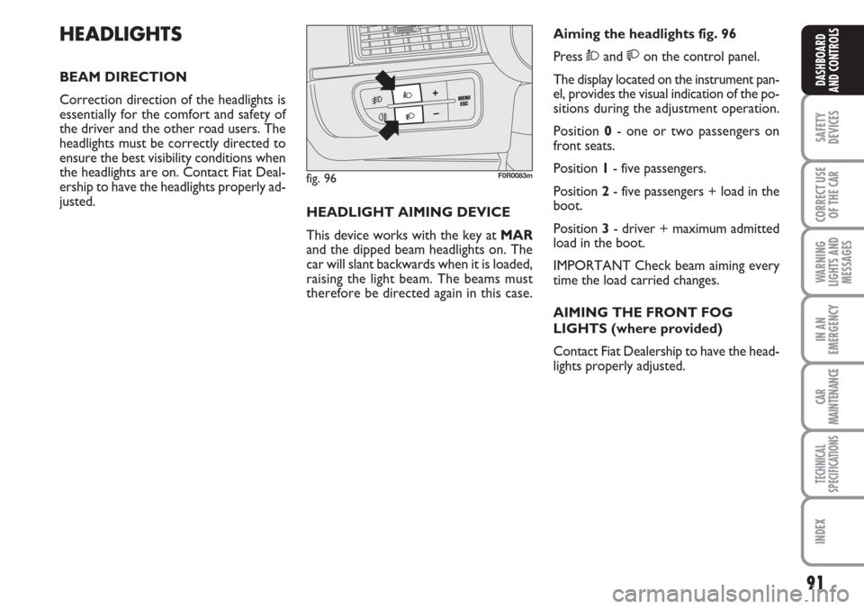
therefore be directed again in this case.Aiming the headlights fig. 96
Press Òand on the control panel.
The display located on the instrument pan-
el, provides the visual indication of the po-
sitions during the adjustment operation.
Position 0- one or two passengers on
front seats.
Position 1- five passengers.
Position 2- five passengers + load in the
boot.
Position 3- driver + maximum admitted
load in the boot.
IMPORTANT Check beam aiming every
time the load carried changes.
AIMING THE FRONT FOG
LIGHTS (where provided)
Contact Fiat Dealership to have the head-
lights properly adjusted.
fig. 96F0R0083m
Page 128 of 230
127
WARNING
LIGHTS AND
MESSAGES
IN AN
EMERGENCY
CAR
MAINTENANCE
TECHNICAL
SPECIFICATIONS
INDEX
DASHBOARD
AND CONTROLS
SAFETY
DEVICES
CORRECT USE
OF THE CAR
Roof rack/ski rack
Remove the roof rack or the ski rack from
the roof after use. These accessories de-
crease aerodynamic penetration of the car
and have a negative effect on consumption.
It is better to use a trailer to transport
particularly bulky objects.
Electric devices
Use electric devices only for the amount
of time needed. Rear heated window, ad-
ditional headlights, windscreen wipers and
heater fan need a considerable amount of
energy, therefore increasing the require-
ment of current increases fuel consump-
tion (up to +25% in the urban cycle).
Climate control
The climate control system requires high-
er fuel consumption (up to +20% in av-
erage): use the air vents when the exter-
nal temperature allows to.
Spoilers
The use of non-certified aerodynamic
items may adversely affect air drag and
consumption levels.DRIVING STYLE
Starting
Do not warm the engine up with the car
standing: the engine warms up very slow-
ly in these conditions, increasing con-
sumption and emissions. It is advisable to
start off immediately and slowly keeping
the engine speed down: the engine will
warm up much faster this way.
Unnecessary actions
Avoid revving up when starting at traffic
lights or before stopping the engine. The
latter action, like doubling the clutch, is un-
necessary and causes increase of con-
sumption and pollution.
Gear selection
Use a higher gear as soon as traffic and
road conditions allow. Using a low gear
for faster acceleration will increase con-
sumption.
In the same way improper use of a high
gear increases consumption, emissions an
engine wear.CONTAINING
RUNNING COSTS
Here are some suggestions which may
help you to keep the running costs of your
car down and lower the amount of toxic
emissions released into the atmosphere.
GENERAL CONSIDERATIONS
Car maintenance
Have checks and adjustments carried out
in accordance with the “Service schedule”.
Tyres
Check tyre pressure regularly at least
once every four weeks: excessively low
pressure will increase consumption be-
cause rolling resistance will be higher.
Unnecessary loads
Do not travel with too much luggage
stowed in the boot. The weight of the car
(especially when driving in town) and its
trim greatly affects consumption and sta-
bility.
Page 134 of 230
133
IN AN
EMERGENCY
CAR
MAINTENANCE
TECHNICAL
SPECIFICATIONS
INDEX
DASHBOARD
AND CONTROLS
SAFETY
DEVICES
CORRECT USE
OF THE
CAR
WARNING
LIGHTS AND
MESSAGES
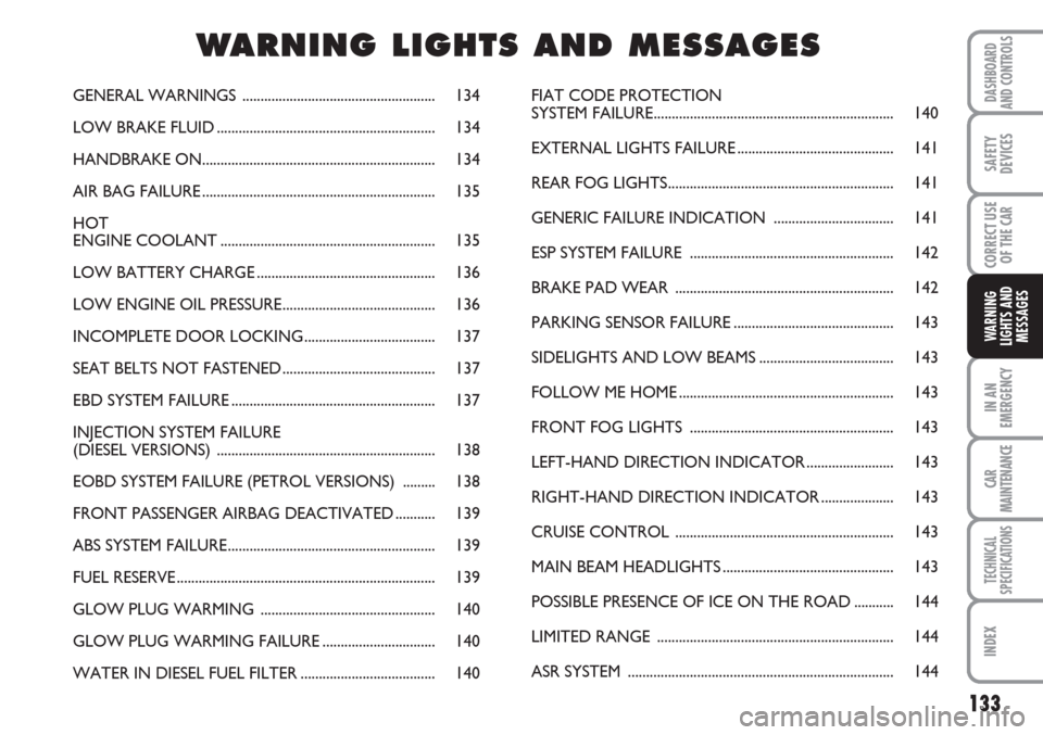
GENERAL WARNINGS ..................................................... 134
LOW BRAKE FLUID............................................................ 134
HANDBRAKE ON................................................................ 134
AIR BAG FAILURE................................................................ 135
HOT
ENGINE COOLANT........................................................... 135
LOW BATTERY CHARGE................................................. 136
LOW ENGINE OIL PRESSURE.......................................... 136
INCOMPLETE DOOR LOCKING.................................... 137
SEAT BELTS NOT FASTENED.......................................... 137
EBD SYSTEM FAILURE........................................................ 137
INJECTION SYSTEM FAILURE
(DIESEL VERSIONS) ............................................................ 138
EOBD SYSTEM FAILURE (PETROL VERSIONS) .........138
FRONT PASSENGER AIRBAG DEACTIVATED........... 139
ABS SYSTEM FAILURE......................................................... 139
FUEL RESERVE....................................................................... 139
GLOW PLUG WARMING ................................................ 140
GLOW PLUG WARMING FAILURE............................... 140
WATER IN DIESEL FUEL FILTER..................................... 140FIAT CODE PROTECTION
SYSTEM FAILURE.................................................................. 140
EXTERNAL LIGHTS FAILURE........................................... 141
REAR FOG LIGHTS.............................................................. 141
GENERIC FAILURE INDICATION ................................. 141
ESP SYSTEM FAILURE ........................................................ 142
BRAKE PAD WEAR ............................................................ 142
PARKING SENSOR FAILURE............................................ 143
SIDELIGHTS AND LOW BEAMS..................................... 143
FOLLOW ME HOME........................................................... 143
FRONT FOG LIGHTS ........................................................ 143
LEFT-HAND DIRECTION INDICATOR........................ 143
RIGHT-HAND DIRECTION INDICATOR.................... 143
CRUISE CONTROL ............................................................ 143
MAIN BEAM HEADLIGHTS............................................... 143
POSSIBLE PRESENCE OF ICE ON THE ROAD ........... 144
LIMITED RANGE ................................................................. 144
ASR SYSTEM ......................................................................... 144
WW W
A A
R R
N N
I I
N N
G G
L L
I I
G G
H H
T T
S S
A A
N N
D D
M M
E E
S S
S S
A A
G G
E E
S S
Page 159 of 230
158
WARNING
LIGHTS AND
MESSAGES
CAR
MAINTENANCE
TECHNICAL
SPECIFICATIONS
IINDEX
DASHBOARD
AND CONTROLS
SAFETY
DEVICES
CORRECT USE
OF THE
CAR
IN AN
EMERGENCY
WHEN NEEDING TO
CHANGE A BULB
GENERAL INSTRUCTIONS
❒When a bulb is not working, check that
the corresponding fuse is intact before
replacing it: refer to the “If a fuse
blows” paragraph in this chapter for
fuse location.
❒before changing a bulb check the con-
tacts for oxidation;
❒burnt bulbs must be replaced by others
of the same type and power;
❒always check the height of the headlight
beam after changing a bulb, for reasons
of safety.
IMPORTANT A slight misting may appear
on the internal surface of the headlight:
this does not indicate a fault and is caused
by low temperature and the degree of hu-
midity in the air. Misting will rapidly dis-
appear when the headlights are switched
on. The presence of drop inside the head-
lights indicates infiltration of water. Go to
a Fiat Dealership.
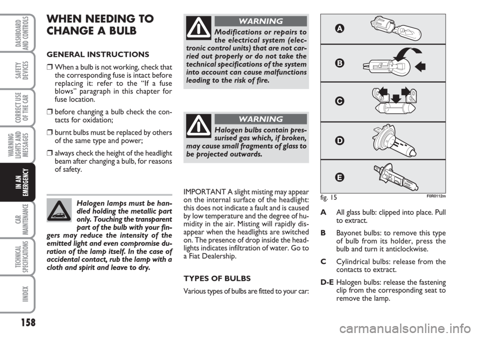
TYPES OF BULBS
Various types of bulbs are fitted to your car:AAll glass bulb: clipped into place. Pull
to extract.
BBayonet bulbs: to remove this type
of bulb from its holder, press the
bulb and turn it anticlockwise.
CCylindrical bulbs: release from the
contacts to extract.
D-EHalogen bulbs: release the fastening
clip from the corresponding seat to
remove the lamp. Halogen lamps must be han-
dled holding the metallic part
only. Touching the transparent
part of the bulb with your fin-
gers may reduce the intensity of the
emitted light and even compromise du-
ration of the lamp itself. In the case of
accidental contact, rub the lamp with a
cloth and spirit and leave to dry.
Modifications or repairs to
the electrical system (elec-
tronic control units) that are not car-
ried out properly or do not take the
technical specifications of the system
into account can cause malfunctions
leading to the risk of fire.
WARNING
Halogen bulbs contain pres-
surised gas which, if broken,
may cause small fragments of glass to
be projected outwards.
WARNING
fig. 15F0R0112m
Page 160 of 230
159
WARNING
LIGHTS AND
MESSAGES
CAR
MAINTENANCE
TECHNICAL
SPECIFICATIONS
INDEX
DASHBOARD
AND CONTROLS
SAFETY
DEVICES
CORRECT USE
OF THE
CAR
IN AN
EMERGENCY
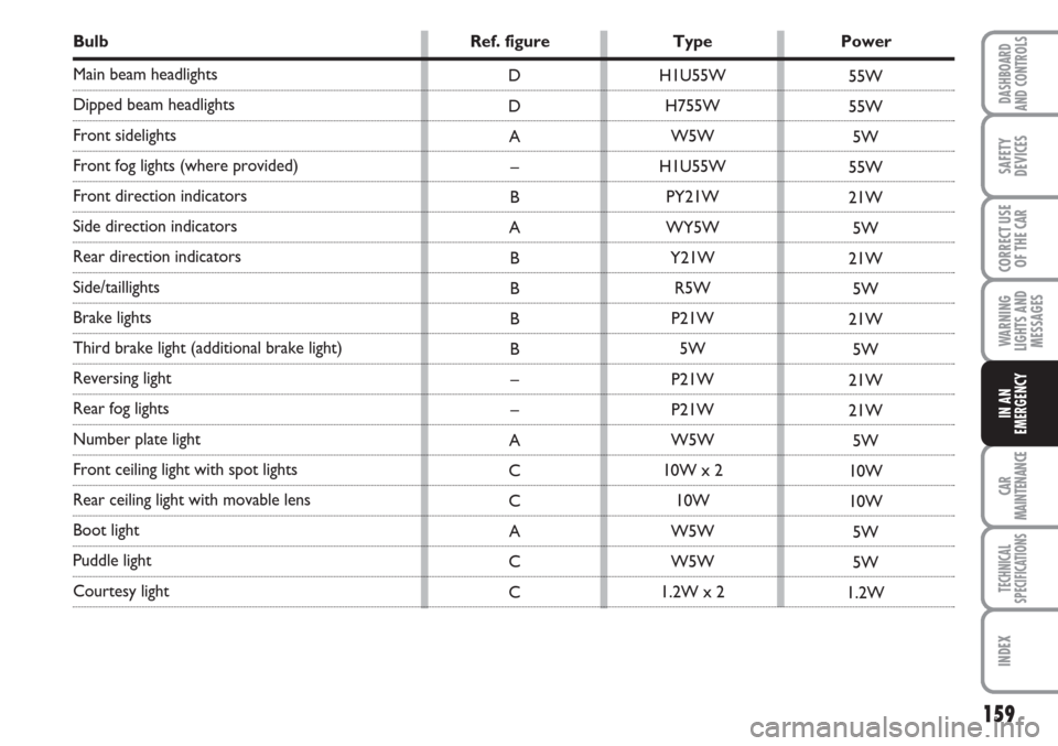
Bulb Ref. figure Type Power
Main beam headlights
Dipped beam headlights
Front sidelights
Front fog lights (where provided)
Front direction indicators
Side direction indicators
Rear direction indicators
Side/taillights
Brake lights
Third brake light (additional brake light)
Reversing light
Rear fog lights
Number plate light
Front ceiling light with spot lights
Rear ceiling light with movable lens
Boot light
Puddle light
Courtesy light H1U55W
H755W
W5W
H1U55W
PY21W
WY5W
Y21W
R5W
P21W
5W
P21W
P21W
W5W
10W x 2
10W
W5W
W5W
1.2W x 2 D
D
A
–
B
A
B
B
B
B
–
–
A
C
C
A
C
C55W
55W
5W
55W
21W
5W
21W
5W
21W
5W
21W
21W
5W
10W
10W
5W
5W
1.2W
Page 162 of 230
161
WARNING
LIGHTS AND
MESSAGES
CAR
MAINTENANCE
TECHNICAL
SPECIFICATIONS
INDEX
DASHBOARD
AND CONTROLS
SAFETY
DEVICES
CORRECT USE
OF THE
CAR
IN AN
EMERGENCY
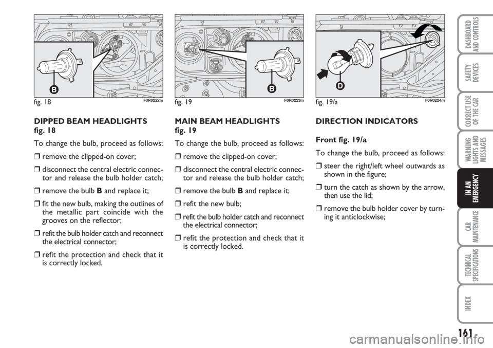
DIPPED BEAM HEADLIGHTS
fig. 18
To change the bulb, proceed as follows:
❒remove the clipped-on cover;
❒disconnect the central electric connec-
tor and release the bulb holder catch;
❒remove the bulb Band replace it;
❒fit the new bulb, making the outlines of
the metallic part coincide with the
grooves on the reflector;
❒refit the bulb holder catch and reconnect
the electrical connector;
❒refit the protection and check that it
is correctly locked.MAIN BEAM HEADLIGHTS
fig. 19
To change the bulb, proceed as follows:
❒remove the clipped-on cover;
❒disconnect the central electric connec-
tor and release the bulb holder catch;
❒remove the bulb Band replace it;
❒refit the new bulb;
❒refit the bulb holder catch and reconnect
the electrical connector;
❒refit the protection and check that it
is correctly locked.DIRECTION INDICATORS
Front fig. 19/a
To change the bulb, proceed as follows:
❒steer the right/left wheel outwards as
shown in the figure;
❒turn the catch as shown by the arrow,
then use the lid;
❒remove the bulb holder cover by turn-
ing it anticlockwise;
fig. 18F0R0222mfig. 19/aF0R0224mfig. 19F0R0223m
Page 171 of 230
170
WARNING
LIGHTS AND
MESSAGES
CAR
MAINTENANCE
TECHNICAL
SPECIFICATIONS
IINDEX
DASHBOARD
AND CONTROLS
SAFETY
DEVICES
CORRECT USE
OF THE
CAR
IN AN
EMERGENCY
7.5
7.5
7.5
15
20
20
7.5
7.5
7.5
20
10
30
7.5
7.5
20 F12
F13
F31
F32
F33
F34
F35
F36
F37
F38
F39
F40
F41
F42
F43
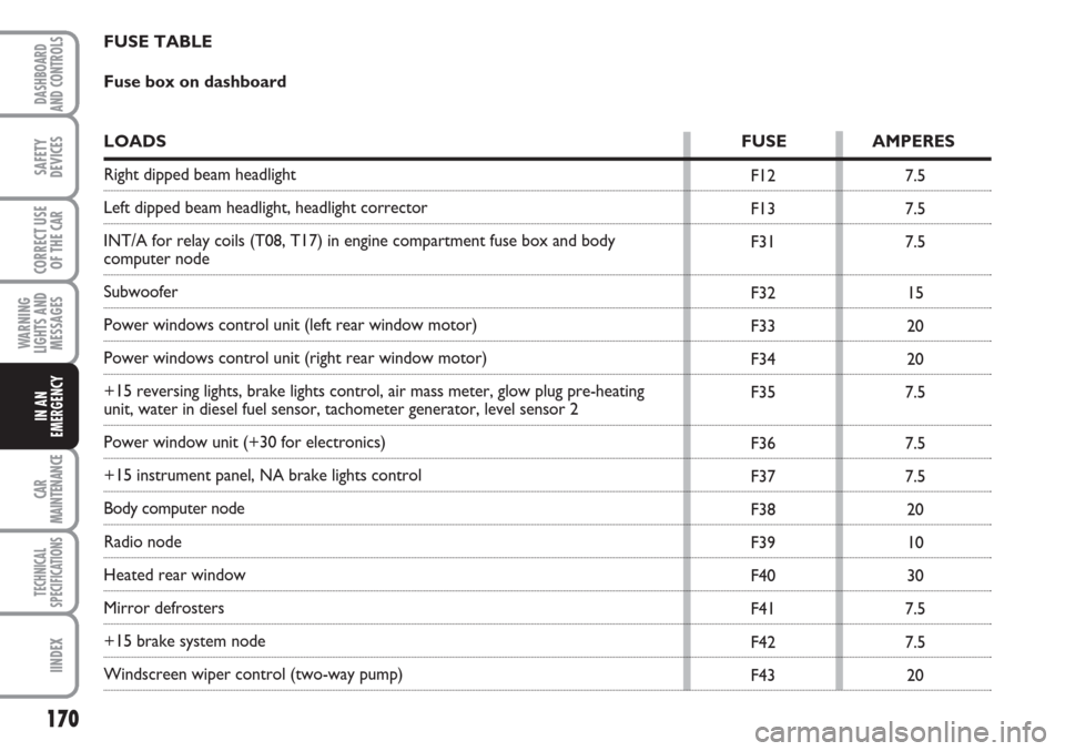
FUSE TABLE
Fuse box on dashboard
LOADS FUSE AMPERES
Right dipped beam headlight
Left dipped beam headlight, headlight corrector
INT/A for relay coils (T08, T17) in engine compartment fuse box and body
computer node
Subwoofer
Power windows control unit (left rear window motor)
Power windows control unit (right rear window motor)
+15 reversing lights, brake lights control, air mass meter, glow plug pre-heating
unit, water in diesel fuel sensor, tachometer generator, level sensor 2
Power window unit (+30 for electronics)
+15 instrument panel, NA brake lights control
Body computer node
Radio node
Heated rear window
Mirror defrosters
+15 brake system node
Windscreen wiper control (two-way pump)