engine FIAT LINEA 2007 1.G Owner's Manual
[x] Cancel search | Manufacturer: FIAT, Model Year: 2007, Model line: LINEA, Model: FIAT LINEA 2007 1.GPages: 230, PDF Size: 3.31 MB
Page 72 of 230
71
SAFETY
DEVICES
CORRECT USE
OF THE
CAR
WARNING
LIGHTS AND
MESSAGES
IN AN
EMERGENCY
CAR
MAINTENANCE
TECHNICAL
SPECIFICATIONS
INDEX
DASHBOARD
AND CONTROLS
RESTORING STORED SPEED
If the device has been disengaged for ex-
ample pressing the brake or clutch pedal,
the memorised speed can be reset as fol-
lows:
❒accelerate gradually until reaching a
speed approaching the one stored;
❒engage the gear selected at the time
when the speed was originally stored;
❒press RES B-fig. 47.
INCREASING THE STORED
SPEED
The stored speed can be increased in two
ways:
❒by pressing the accelerator and then
storing the new speed reached;
or
❒by moving the stalk upwards (+).
Each operation of the stalk will corre-
spond to a slight increase in speed (about
1 km/h), while keeping the stalk upwards
will correspond to a continuous speed in-
crease. REDUCING THE STORED SPEED
The stored speed can be increased in two
ways:
❒by switching the device off and then
storing a new speed;
or
❒by moving the stalk downwards (–) un-
til reaching the new speed which will be
stored automatically.
Each operation of the stalk will corre-
spond to a slight reduction in speed (about
1 km/h), while keeping the stalk down-
wards will correspond to a continuous
speed reduction.
SWITCHING THE DEVICE OFF
The device can be switch off in the fol-
lowing ways:
❒by turning knob Ato OFF;
❒by turning the engine off;
❒by pressing the brake pedal;
❒by pressing the clutch pedal;
❒by pressing the accelerator pedal; in this
case the system is not really switched
off but the request for acceleration
takes priority over the system. The
cruise control is however active and it
will not be necessary to press button
RES B-fig. 47to resume previous con-
ditions after ending acceleration.
The device is automatically switched off in
one of the following cases:
❒if the ABSor ESPsystems cut-in;
❒with car speed below the preset limit;
❒in the case of system failure.
When travelling with the de-
vice on, never set the
gearshift lever to neutral.
WARNING
In the event of device faults
or failures, turn knob A to
OFF and contact a Fiat Dealership.
WARNING
Page 73 of 230
72
SAFETY
DEVICES
CORRECT USE
OF THE
CAR
WARNING
LIGHTS AND
MESSAGES
IN AN
EMERGENCY
CAR
MAINTENANCE
TECHNICAL
SPECIFICATIONS
INDEX
DASHBOARD
AND CONTROLS
CEILING LIGHTS
FRONT CEILING WITH SPOT
LIGHTS fig.48 /a AND WITH
DIFFUSED LIGHTIING LED
(where provided) fig.48 /b
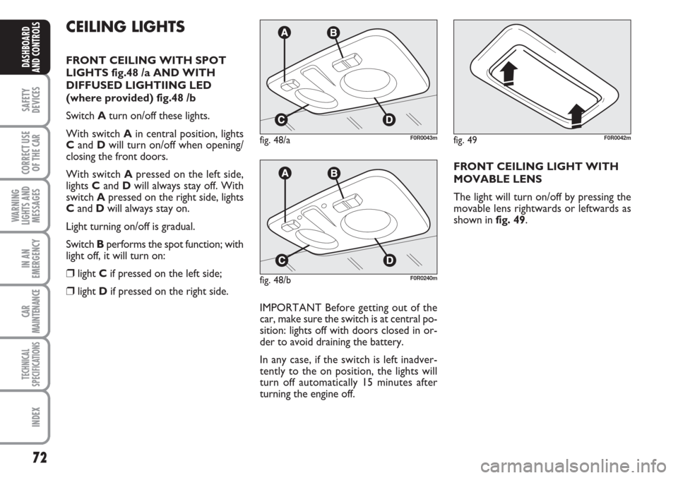
Switch Aturn on/off these lights.
With switch Ain central position, lights
Cand Dwill turn on/off when opening/
closing the front doors.
With switch Apressed on the left side,
lights Cand Dwill always stay off. With
switch Apressed on the right side, lights
Cand Dwill always stay on.
Light turning on/off is gradual.
Switch Bperforms the spot function; with
light off, it will turn on:
❒light Cif pressed on the left side;
❒light Dif pressed on the right side.
IMPORTANT Before getting out of the
car, make sure the switch is at central po-
sition: lights off with doors closed in or-
der to avoid draining the battery.
In any case, if the switch is left inadver-
tently to the on position, the lights will
turn off automatically 15 minutes after
turning the engine off.
fig. 48/aF0R0043m
FRONT CEILING LIGHT WITH
MOVABLE LENS
The light will turn on/off by pressing the
movable lens rightwards or leftwards as
shown in fig. 49.
fig. 48/bF0R0240m
fig. 49F0R0042m
Page 78 of 230
77
SAFETY
DEVICES
CORRECT USE
OF THE
CAR
WARNING
LIGHTS AND
MESSAGES
IN AN
EMERGENCY
CAR
MAINTENANCE
TECHNICAL
SPECIFICATIONS
INDEX
DASHBOARD
AND CONTROLS
Door unlocking in the event
of a crash
If the fuel cut-off switch trips following an
accident, the doors will be automatically
unlocked to let you leave the car and the
ceiling lights will be switched on at the
same time. The doors can always be
opened from the inside of the car by
means of the specific levers.
Proceed as follows if no fuel leakage is
found and and the car is in condition to be
driven to rearm the fuel cut-off switch.FUEL CUT-OFF SWITCH
The car is fitted with a safety switch that
in the event of a crash comes into opera-
tion by cutting off fuel and turning off the
engine as a consequence.
This device therefore prevents fuel leaks
due to fuel piping breaking.
IMPORTANT After the accident, re-
member to remove the electronic key
from the ignition device to prevent drain-
ing the battery.The message “FPS on” will appear on the
digital display when the switch trips. The
message “Inertia switch tripped. See hand-
book” will appear on the multifunctional
display.
If, after a crash, you smell fu-
el or see leaks from the fuel
system, do not reset the switch to
avoid fine risk.
WARNING
If the centralised door lock-
ing system was operated
from inside the car and the fuel cut-
off switch did not manage to auto-
matically release the doors, it will not
be possible to access the passenger
compartment from the outside after
an accident. The possibility of open-
ing the doors from the outside de-
pends on the conditions of the doors
themselves after the accident: if may
not be possible to open a damaged
door. In this case, try to open the oth-
er doors of the car.
WARNING
Page 90 of 230
89
SAFETY
DEVICES
CORRECT USE
OF THE
CAR
WARNING
LIGHTS AND
MESSAGES
IN AN
EMERGENCY
CAR
MAINTENANCE
TECHNICAL
SPECIFICATIONS
INDEX
DASHBOARD
AND CONTROLS
IMPORTANT Before opening the bonnet,
check that windscreen wiper arms are not
lifted from the windscreen.CLOSING THE BONNET
Proceed as follows:
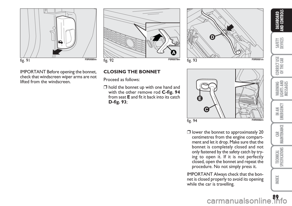
❒hold the bonnet up with one hand and
with the other remove rod C-fig. 94
from seat Eand fit it back into its catch
D-fig. 93;
❒lower the bonnet to approximately 20
centimetres from the engine compart-
ment and let it drop. Make sure that the
bonnet is completely closed and not
only fastened by the safety catch by try-
ing to open it. If it is not perfectly
closed, open the bonnet and repeat the
procedure. No not simply press it.
IMPORTANT Always check that the bon-
net is closed properly to avoid its opening
while the car is travelling.
fig. 91F0R0080mfig. 92F0R0079m
fig. 94F0R0082m
fig. 93F0R0081m
Page 94 of 230
93
SAFETY
DEVICES
CORRECT USE
OF THE
CAR
WARNING
LIGHTS AND
MESSAGES
IN AN
EMERGENCY
CAR
MAINTENANCE
TECHNICAL
SPECIFICATIONS
INDEX
DASHBOARD
AND CONTROLS
BRAKE ASSIST
(integrated ESP emergency
braking assistance)
(where provided)
This system (which cannot be deactivat-
ed) recognises emergency braking condi-
tions according to the speed of operation
of the brake pedal and provides an addi-
tional hydraulic braking pressure to sup-
port that provided by the driver. This al-
lows faster and more power operation of
the braking system.
Brake Assist is deactivated on the versions
equipped with ESP, in the event of ESP sys-
tem failure (indicated by warning light
áswitching on together with the message
on the multifunctional display, where pro-
vided).
ESP SYSTEM
(Electronic Stability
Program)
(where provided)
The ESP system is an electronic system
controlling the car stability in the event of
tyre grip loss.
The ESP system is therefore particularly
useful when grip conditions of the road sur-
faces changes.
In addition to the ESP system, ASR system
and Hill Holder, (where provided) also the
MSR system (adjusting the engine braking
torque) and the HBA system (improving
the braking force during emergency brak-
ing) are provided.
ABS SYSTEM INTERVENTION
It is signalled by the blinking of the warn-
ing light
áon the instrument panel, to
inform the driver that the car is in criti-
cal stability and grip conditions.When the ABS cuts in, and
you feel the brake pedal pul-
sating, do not remove your foot, but
keep it pressed; in doing so you will
stop in the shortest amount of space
possible under the current road con-
ditions.
WARNING
EBD failure
ABS failure is indicated by the turning on
warning lights
>and xon the instru-
ment panel together with the dedicated
message on the multifunctional display
(where provided), (see section “Warning
lights and messages”).
In this case, the rear wheels may sudden-
ly lock and the car may swerve. Drive
carefully to the nearest Fiat Dealership to
have the system checked.
If warning light xonly lights
up on the instrument panel
(with a message on the multifunc-
tional display, where provided), stop
the car immediate and go to the
nearest Fiat Dealership. Leakage of
hydraulic fluid from the braking sys-
tem will compromise functionality of
the braking system, either of the con-
ventional type or with ABS.
WARNING
Page 95 of 230
94
SAFETY
DEVICES
CORRECT USE
OF THE
CAR
WARNING
LIGHTS AND
MESSAGES
IN AN
EMERGENCY
CAR
MAINTENANCE
TECHNICAL
SPECIFICATIONS
INDEX
DASHBOARD
AND CONTROLS
ESP SYSTEM ACTIVATION
The ESP system is automatically activat-
ed when the car is started and cannot be
de-activated.
FAILURE INDICATIONS
In the event of a failure, the In ESP will be
automatically switched off and warning
light
áwill appear on the instrument pan-
el along with a message on the multifunc-
tional display (where provided) (see
“Warning lights and messages”). The LED
on the ASR OFF button will light up. Con-
tact Fiat Dealership as soon as possible.
Do not take unnecessary
risks, even if your cars fits an
ESP system. Your driving style must
always be suited to the conditions of
the road, visibility and traffic. The dri-
ver is always and only responsible for
road safety.
WARNING
HILL HOLDER SYSTEM
This system is an integral part of the ESP
system and it is provided to facilitate start-
ing on slopes.
It will activate automatically with the fol-
lowing conditions:
❒uphill: car at a standstill on a road with
a gradient higher than 5%, engine run-
ning, clutch and brake pedal pressed,
gearbox to neutral or engaged gear oth-
er than reverse.
❒downhill: car at a standstill on a road
with a gradient higher than 5%, engine
running, clutch and brake pedal pressed
and reverse gear engaged.
At pickup the ESP system control unit will
keep brake force on wheels until reaching
the torque suitable for starting, or in any
case for max. 2 seconds in order to pass
easily from the brake pedal to the accel-
erator pedal.
After 2 seconds without starting, the sys-
tem will deactivate automatically by re-
leasing gradually the brake force.
At releasing, the typical brake disengage-
ment noise indicating that the car is go-
ing to move will be heard.Failure indications
Warning light
èon the instrument pan-
el will light up in the event of a failure (see
“Warning lights and messages”).
IMPORTANT The Hill Holder system is
not a parking brake therefore, never leave
the car without having engaged the hand-
brake, turned the engine off and engaged
the first speed.
For correct operation of the
ESP and ASR systems, the
tyres must absolutely be of the same
brand and type on all wheels, in per-
fect conditions and, above all, of
type, brand and size specified.
WARNING
Page 96 of 230
95
SAFETY
DEVICES
CORRECT USE
OF THE
CAR
WARNING
LIGHTS AND
MESSAGES
IN AN
EMERGENCY
CAR
MAINTENANCE
TECHNICAL
SPECIFICATIONS
INDEX
DASHBOARD
AND CONTROLS
MSR system
(engine braking torque control)
It is an integral part of the ASR system that
in case of sudden gear shifting, cuts in pro-
viding torque to the engine thus prevent-
ing excessive driving wheel drive that, spe-
cially in poor grip conditions, can lead to
loss of stability.
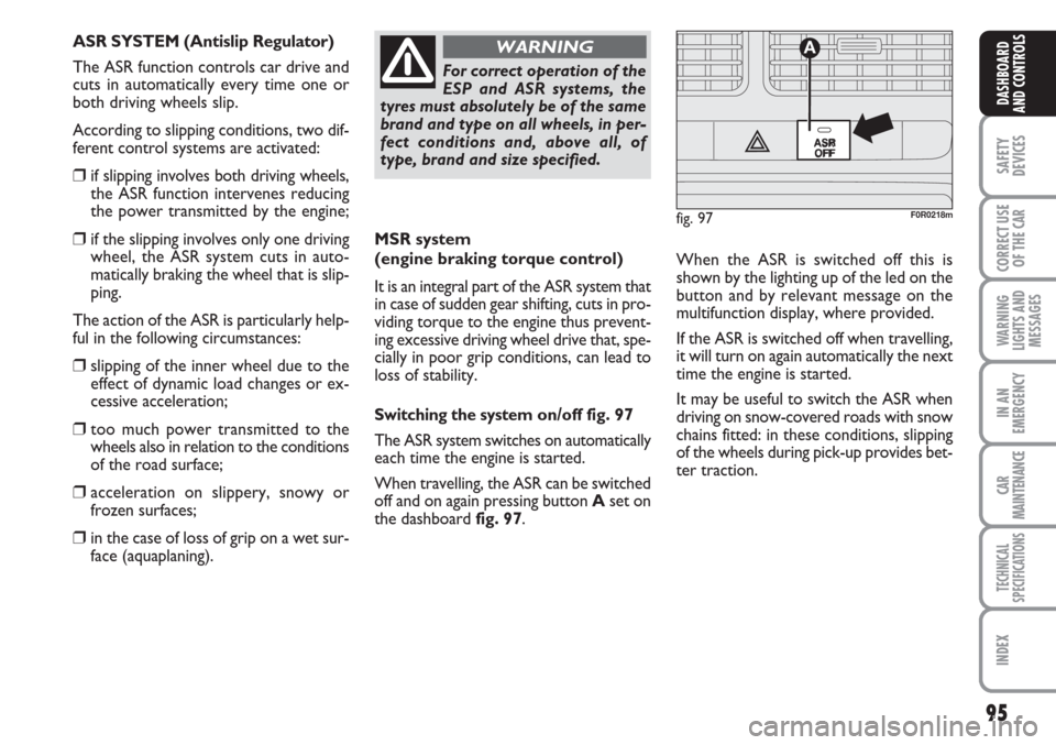
Switching the systemon/off fig. 97
The ASR system switches on automatically
each time the engine is started.
When travelling, the ASR can be switched
off and on again pressing button Aset on
the dashboard fig. 97. When the ASR is switched off this is
shown by the lighting up of the led on the
button and by relevant message on the
multifunction display, where provided.
If the ASR is switched off when travelling,
it will turn on again automatically the next
time the engine is started.
It may be useful to switch the ASR when
driving on snow-covered roads with snow
chains fitted: in these conditions, slipping
of the wheels during pick-up provides bet-
ter traction.
For correct operation of the
ESP and ASR systems, the
tyres must absolutely be of the same
brand and type on all wheels, in per-
fect conditions and, above all, of
type, brand and size specified.
WARNING
fig. 97
ASR
OFF
A
F0R0218m
ASR SYSTEM (Antislip Regulator)
The ASR function controls car drive and
cuts in automatically every time one or
both driving wheels slip.
According to slipping conditions, two dif-
ferent control systems are activated:
❒if slipping involves both driving wheels,
the ASR function intervenes reducing
the power transmitted by the engine;
❒if the slipping involves only one driving
wheel, the ASR system cuts in auto-
matically braking the wheel that is slip-
ping.
The action of the ASR is particularly help-
ful in the following circumstances:
❒slipping of the inner wheel due to the
effect of dynamic load changes or ex-
cessive acceleration;
❒too much power transmitted to the
wheels also in relation to the conditions
of the road surface;
❒acceleration on slippery, snowy or
frozen surfaces;
❒in the case of loss of grip on a wet sur-
face (aquaplaning).
Page 97 of 230
96
SAFETY
DEVICES
CORRECT USE
OF THE
CAR
WARNING
LIGHTS AND
MESSAGES
IN AN
EMERGENCY
CAR
MAINTENANCE
TECHNICAL
SPECIFICATIONS
INDEX
DASHBOARD
AND CONTROLS
Do not take unnecessary
risks, even if your cars fits
such a system. Your driving style must
always be suited to the conditions of
the road, visibility and traffic. The dri-
ver is always and only responsible for
road safety.
WARNING
For correct operation of the ASR system,
the tyres must absolutely be of the same
brand and type on all wheels, in perfect
conditions and, above all, of type, brand
and size specified.
FAILURE INDICATIONS
In the event of a failure, the In ASR will be
automatically switched off and warning
light
áwill appear on the instrument
panel along with a message on the multi-
functional display (where provided) (see
“Warning lights and messages”). In this
case, contact Fiat Dealership as soon as
possible.
EOBD SYSTEM
(where provided)
The EOBD system (European On Board
Diagnosis) allows continuous diagnosis of
the components of the car correlated with
emissions.
It also alerts the driver, by turning on the
warning light
Uon the instrument pan-
el (together with relevant message on the
multifunctional display, where provided)
(see section “Warning lights and mes-
sages”), when these conditions are no
longer in peak conditions.
The objective is:
❒to monitor system efficiency;
❒warn when a fault causes emissions lev-
els to increase;
❒to warn of the need to replace deteri-
orated components.
The system also has a diagnostic connec-
tor that can be interfaced with appropri-
ate tools, which makes it possible to read
the error codes stored in the control unit,
together with a series of specific parame-
ters for engine operation and diagnosis.
This check can also be carried out by the
traffic police.IMPORTANT After eliminating the in-
convenience, to check the system com-
pletely, Fiat Dealerships are obliged to run
a bench test and, if necessary, road tests
which may also call for a long journey.
Go to a Fiat Dealership as
soon as possible if warning
light Ueither does not light
up when the key is turned to
MAR to if while travelling the warning
lights comes on either steady or blink-
ing (along with a message on the mul-
tifunctional display, where provided).
The operation of warning light Umay
be checked by the traffic police using
specific devices. Follow the laws in
force in the country where you are dri-
ving.
Page 102 of 230
101
SAFETY
DEVICES
CORRECT USE
OF THE
CAR
WARNING
LIGHTS AND
MESSAGES
IN AN
EMERGENCY
CAR
MAINTENANCE
TECHNICAL
SPECIFICATIONS
INDEX
DASHBOARD
AND CONTROLS
AT THE FILLING
STATION
PETROL ENGINES
Use only unleaded petrol.
To avoid mistakes, the diameter of the fu-
el filler is too small to introduce the beak
of a leaded petrol pump. The petrol oc-
tane rating (RON) must not be lower
than 95.
IMPORTANT An inefficient catalyst leads
to harmful exhaust emissions, thus con-
tributing to air pollution.
IMPORTANT Never use leaded petrol,
even in small amount or in an emergency,
as this would damage the catalyst beyond
repair.DIESEL ENGINES
If the outside temperature is very low, the
diesel thickens due to the formation of
paraffin clots and could clog the diesel fu-
el filter.
In order to avoid these problems, differ-
ent types of diesel are distributed ac-
cording to the season: summer type, win-
ter type and arctic type (cold, mountain
areas).
If refuelling with diesel fuel whose features
are not suitable to the temperature of use,
it is advisable to mix TUTELA DIESEL ART
additive in the proportions shown on the
container with the fuel. Pour the additive
into the tank before the fuel.
When using or parking the car for a long
time in the mountains or cold areas, it is
advisable to refuel using locally available
fuel.
In this case, it is also advisable to keep the
tank over 50% full.For diesel engines, use diesel
fuel for motor vehicles com-
pliant with EN590 European
specifications only. The use of
other products or mixtures may dam-
age the engine beyond repair and con-
sequently cause lapse of warranty in
relation to the damage caused. If you
accidentally introduce other types of
fuel in the tank, do not start the engine
and empty the tank. If the engine has
run also for a very short time, you will
need to have the entire fuel feed sys-
tem emptied in addition to the tank.
Filling the tank
To fill the tank completely, top-up twice
after the pump switches off. Further top-
ups could cause faults in the fuel feeding
system.
Page 103 of 230
102
SAFETY
DEVICES
CORRECT USE
OF THE
CAR
WARNING
LIGHTS AND
MESSAGES
IN AN
EMERGENCY
CAR
MAINTENANCE
TECHNICAL
SPECIFICATIONS
INDEX
DASHBOARD
AND CONTROLS
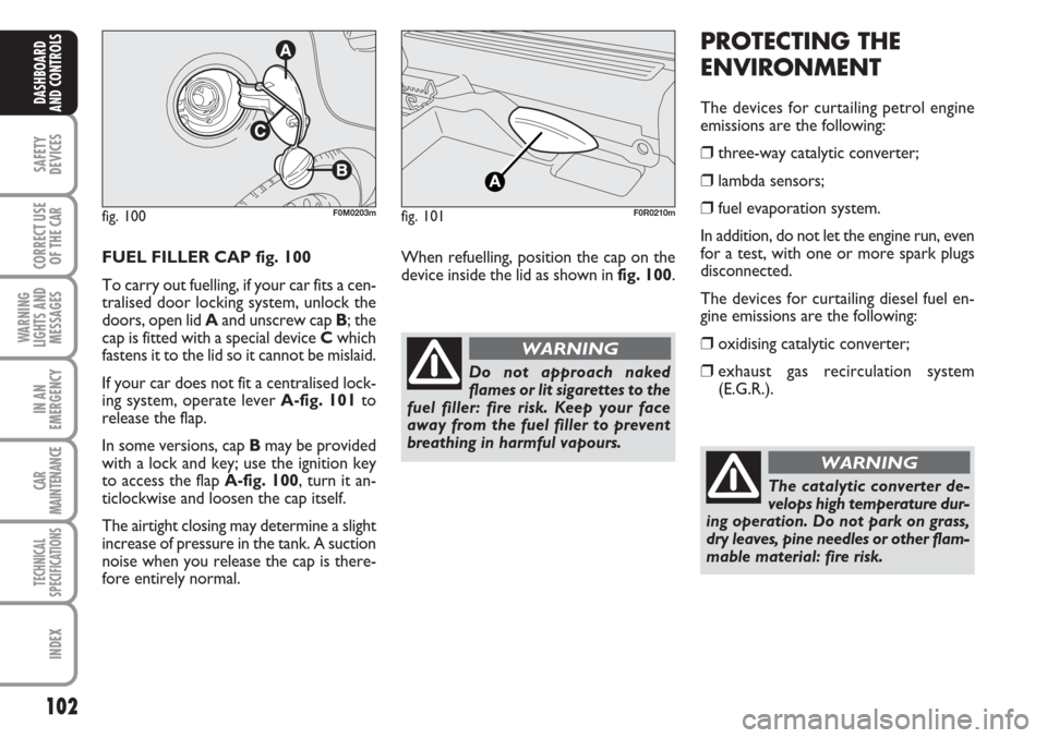
FUEL FILLER CAP fig. 100
To carry out fuelling, if your car fits a cen-
tralised door locking system, unlock the
doors, open lid Aand unscrew cap B; the
cap is fitted with a special device Cwhich
fastens it to the lid so it cannot be mislaid.
If your car does not fit a centralised lock-
ing system, operate lever A-fig. 101to
release the flap.
In some versions, cap Bmay be provided
with a lock and key; use the ignition key
to access the flap A-fig. 100, turn it an-
ticlockwise and loosen the cap itself.
The airtight closing may determine a slight
increase of pressure in the tank. A suction
noise when you release the cap is there-
fore entirely normal.
PROTECTING THE
ENVIRONMENT
The devices for curtailing petrol engine
emissions are the following:
❒three-way catalytic converter;
❒lambda sensors;
❒fuel evaporation system.
In addition, do not let the engine run, even
for a test, with one or more spark plugs
disconnected.
The devices for curtailing diesel fuel en-
gine emissions are the following:
❒oxidising catalytic converter;
❒exhaust gas recirculation system
(E.G.R.).
fig. 100F0M0203m
Do not approach naked
flames or lit sigarettes to the
fuel filler: fire risk. Keep your face
away from the fuel filler to prevent
breathing in harmful vapours.
WARNING
fig. 101F0R0210m
When refuelling, position the cap on the
device inside the lid as shown in fig. 100.
The catalytic converter de-
velops high temperature dur-
ing operation. Do not park on grass,
dry leaves, pine needles or other flam-
mable material: fire risk.
WARNING