seat FIAT LINEA 2008 1.G Owners Manual
[x] Cancel search | Manufacturer: FIAT, Model Year: 2008, Model line: LINEA, Model: FIAT LINEA 2008 1.GPages: 234, PDF Size: 3.41 MB
Page 5 of 234
4
SAFETY
DEVICES
CORRECT USE
OF THE
CAR
WARNING
LIGHTS AND
MESSAGES
IN AN
EMERGENCY
CAR
MAINTENANCE
TECHNICAL
SPECIFICATIONS
INDEX
DASHBOARD
AND CONTROLSDASHBOARD........................................................................ 5
SYMBOLS ............................................................................... 6
THE FIAT CODE SYSTEM.................................................. 6
THE KEYS .............................................................................. 8
ALARM ................................................................................... 11
IGNITION DEVICE.............................................................. 13
INSTRUMENT PANEL ........................................................ 14
INSTRUMENTS..................................................................... 16
DIGITAL DISPLAY ............................................................... 18
MULTIFUNCTION DISPLAY ............................................ 23
RECONFIGURABLE MULTIFUNCTION DISPLAY ....... 32
TRIP COMPUTER ................................................................ 42
FRONT SEATS ..................................................................... 44
REAR SEATS .......................................................................... 45
HEAD RESTRAINTS............................................................. 45
STEERING WHEEL .............................................................. 47
REARVIEW MIRRORS......................................................... 47
HEATING AND VENTILATION...................................... 49
MANUAL CLIMATE CONTROL SYSTEM .................... 53
AUTOMATIC CLIMATE CONTROL SYSTEM ............ 59EXTERNAL LIGHTS ............................................................ 66
WINDOW WASHING....................................................... 68
CRUISE CONTROL ............................................................ 70
CEILING LIGHTS.................................................................. 72
CONTROLS........................................................................... 75
FUEL CUT-OFF SWITCH .................................................. 77
INTERIOR FITTINGS........................................................... 78
DOORS .................................................................................. 82
POWER WINDOWS........................................................... 83
BOOT ...................................................................................... 86
BONNET................................................................................. 88
ROOF RACK/SKI RACK .................................................... 90
HEADLIGHTS........................................................................ 91
ABS SYSTEM ......................................................................... 92
ESP SYSTEM .......................................................................... 93
EOBD SYSTEM ..................................................................... 96
PARKING SENSORS ........................................................... 97
SOUND SYSTEM.................................................................. 99
ACCESSORIES PURCHASED BY THE OWNER .......... 100
AT THE FILLING STATION ............................................. 101
PROTECTING THE ENVIRONMENT............................. 102
DD D
A A
S S
H H
B B
O O
A A
R R
D D
A A
N N
D D
C C
O O
N N
T T
R R
O O
L L
S S
001-031 LINEA 1ed GB 4-09-2008 14:55 Pagina 4
Page 45 of 234
44
SAFETY
DEVICES
CORRECT USE
OF THE
CAR
WARNING
LIGHTS AND
MESSAGES
IN AN
EMERGENCY
CAR
MAINTENANCE
TECHNICAL
SPECIFICATIONS
INDEX
DASHBOARD
AND CONTROLS
The fabric upholstery of your
car is designed to withstand
the normal wear and tear of
your car for a long time. Some
precautions are however needed. Avoid
prolonged rubbing against clothing ac-
cessories, such as metal buckles, Velcro
strips and the like, which by applying a
high pressure on the fabric in a small
area could cause the breakage of some
threads and damage the upholstery.
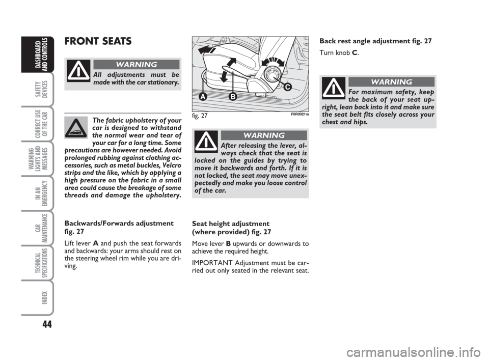
Seat height adjustment
(where provided) fig. 27
Move lever Bupwards or downwards to
achieve the required height.
IMPORTANT Adjustment must be car-
ried out only seated in the relevant seat.
FRONT SEATS
fig. 27F0R0021m
All adjustments must be
made with the car stationary.
WARNING
Backwards/Forwards adjustment
fig. 27
Lift lever Aand push the seat forwards
and backwards: your arms should rest on
the steering wheel rim while you are dri-
ving.
After releasing the lever, al-
ways check that the seat is
locked on the guides by trying to
move it backwards and forth. If it is
not locked, the seat may move unex-
pectedly and make you loose control
of the car.
WARNING
For maximum safety, keep
the back of your seat up-
right, lean back into it and make sure
the seat belt fits closely across your
chest and hips.
WARNING
Back rest angle adjustment fig. 27
Turn knob C.
044-090 LINEA 1ed GB 3-09-2008 17:29 Pagina 44
Page 46 of 234
45
SAFETY
DEVICES
CORRECT USE
OF THE
CAR
WARNING
LIGHTS AND
MESSAGES
IN AN
EMERGENCY
CAR
MAINTENANCE
TECHNICAL
SPECIFICATIONS
INDEX
DASHBOARD
AND CONTROLS
fig. 28F0R0022m
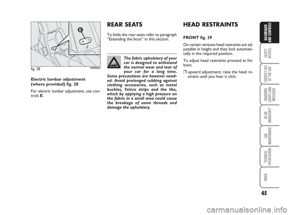
Electric lumbar adjustment
(where provided) fig. 28
For electric lumbar adjustment, use con-
trols E.The fabric upholstery of your
car is designed to withstand
the normal wear and tear of
your car for a long time.
Some precautions are however need-
ed. Avoid prolonged rubbing against
clothing accessories, such as metal
buckles, Velcro strips and the like,
which by applying a high pressure on
the fabric in a small area could cause
the breakage of some threads and
damage the upholstery.
HEAD RESTRAINTS
FRONT fig. 29
On certain versions head restraints are ad-
justable in height and they lock automati-
cally in the required position.
To adjust head restraints proceed as fol-
lows:
❒upward adjustment: raise the head re-
straint until you hear it click.
REAR SEATS
To folds the rear seats refer to paragraph
“Extending the boot” in this section.
044-090 LINEA 1ed GB 3-09-2008 17:29 Pagina 45
Page 47 of 234
46
SAFETY
DEVICES
CORRECT USE
OF THE
CAR
WARNING
LIGHTS AND
MESSAGES
IN AN
EMERGENCY
CAR
MAINTENANCE
TECHNICAL
SPECIFICATIONS
INDEX
DASHBOARD
AND CONTROLS
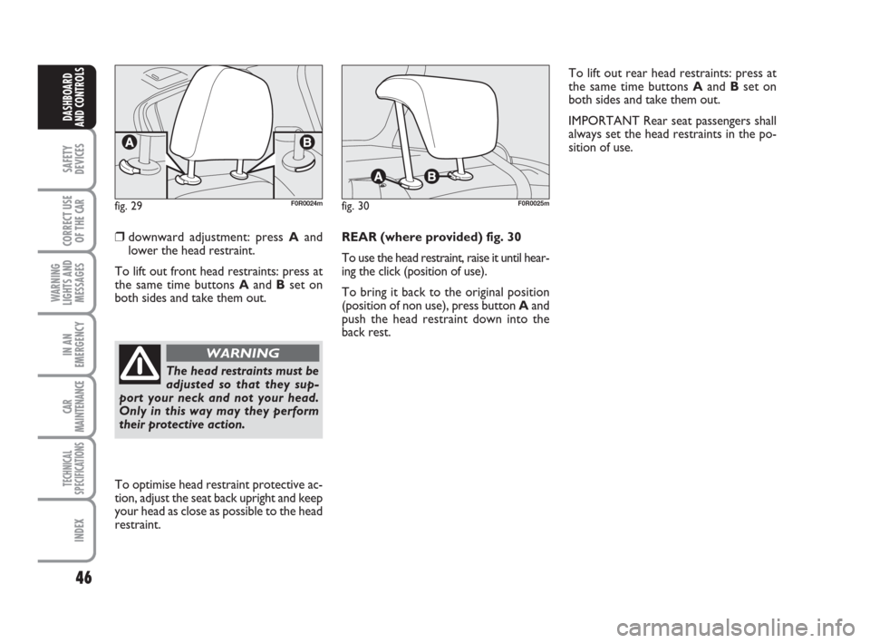
❒downward adjustment: press Aand
lower the head restraint.
To lift out front head restraints: press at
the same time buttons Aand Bset on
both sides and take them out.REAR (where provided) fig. 30
To use the head restraint, raise it until hear-
ing the click (position of use).
To bring it back to the original position
(position of non use), press button Aand
push the head restraint down into the
back rest.
fig. 29F0R0024mfig. 30F0R0025m
To optimise head restraint protective ac-
tion, adjust the seat back upright and keep
your head as close as possible to the head
restraint.
The head restraints must be
adjusted so that they sup-
port your neck and not your head.
Only in this way may they perform
their protective action.
WARNING
To lift out rear head restraints: press at
the same time buttons Aand Bset on
both sides and take them out.
IMPORTANT Rear seat passengers shall
always set the head restraints in the po-
sition of use.
044-090 LINEA 1ed GB 3-09-2008 17:29 Pagina 46
Page 50 of 234
49
SAFETY
DEVICES
CORRECT USE
OF THE
CAR
WARNING
LIGHTS AND
MESSAGES
IN AN
EMERGENCY
CAR
MAINTENANCE
TECHNICAL
SPECIFICATIONS
INDEX
DASHBOARD
AND CONTROLS
fig. 36
F0R0031m
HEATING AND VENTILATION
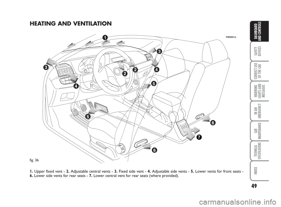
1.Upper fixed vent - 2.Adjustable central vents - 3.Fixed side vent - 4.Adjustable side vents - 5. Lower vents for front seats -
6.Lower side vents for rear seats - 7.Lower central vent for rear seats (where provided).
044-090 LINEA 1ed GB 3-09-2008 17:29 Pagina 49
Page 80 of 234
79
SAFETY
DEVICES
CORRECT USE
OF THE
CAR
WARNING
LIGHTS AND
MESSAGES
IN AN
EMERGENCY
CAR
MAINTENANCE
TECHNICAL
SPECIFICATIONS
INDEX
DASHBOARD
AND CONTROLS
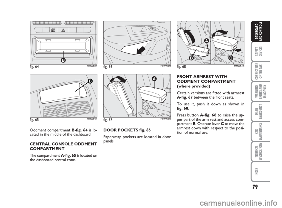
DOOR POCKETS fig. 66
Paper/map pockets are located in door
panels.FRONT ARMREST WITH
ODDMENT COMPARTMENT
(where provided)
Certain versions are fitted with armrest
A-fig. 67between the front seats.
To use it, push it down as shown in
fig. 68.
Press button A-fig. 68to raise the up-
per part of the arm rest and access com-
partment B. Operate lever Cto move the
armrest down with respect to the posi-
tion of normal use.
fig. 64F0R0053m
fig. 65F0R0054mfig. 67F0R0056m
fig. 68F0R0057mfig. 66F0R0055m
Oddment compartment B-fig. 64 is lo-
cated in the middle of the dashboard.
CENTRAL CONSOLE ODDMENT
COMPARTMENT
The compartiment A-fig. 65is located on
the dashboard central zone.
044-090 LINEA 1ed GB 3-09-2008 17:29 Pagina 79
Page 82 of 234
81
SAFETY
DEVICES
CORRECT USE
OF THE
CAR
WARNING
LIGHTS AND
MESSAGES
IN AN
EMERGENCY
CAR
MAINTENANCE
TECHNICAL
SPECIFICATIONS
INDEX
DASHBOARD
AND CONTROLS
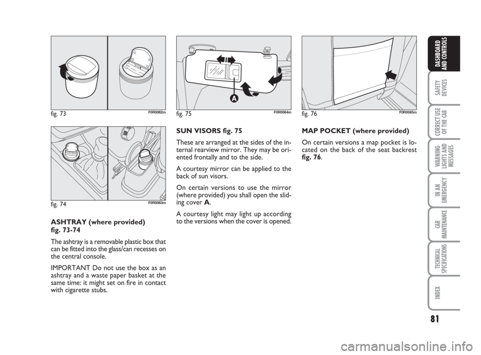
ASHTRAY (where provided)
fig. 73-74
The ashtray is a removable plastic box that
can be fitted into the glass/can recesses on
the central console.
IMPORTANT Do not use the box as an
ashtray and a waste paper basket at the
same time: it might set on fire in contact
with cigarette stubs.SUN VISORS fig. 75
These are arranged at the sides of the in-
ternal rearview mirror. They may be ori-
ented frontally and to the side.
A courtesy mirror can be applied to the
back of sun visors.
On certain versions to use the mirror
(where provided) you shall open the slid-
ing cover A.
A courtesy light may light up according
to the versions when the cover is opened.
fig. 73F0R0062mfig. 75F0R0064mfig. 76F0R0065m
fig. 74F0R0063m
MAP POCKET (where provided)
On certain versions a map pocket is lo-
cated on the back of the seat backrest
fig. 76.
044-090 LINEA 1ed GB 3-09-2008 17:29 Pagina 81
Page 87 of 234
86
SAFETY
DEVICES
CORRECT USE
OF THE
CAR
WARNING
LIGHTS AND
MESSAGES
IN AN
EMERGENCY
CAR
MAINTENANCE
TECHNICAL
SPECIFICATIONS
INDEX
DASHBOARD
AND CONTROLS
BOOT
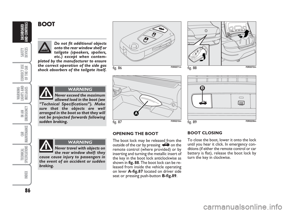
OPENING THE BOOT
The boot lock may be released from the
outside of the car by pressing
Ron the
remote control (where provided) or by
inserting and turning the metallic insert of
the key in the boot lock anticlockwise as
shown in fig. 88. The boot lock can be re-
leased from inside the vehicle operating
on lever A-fig.87 located on driver side
seat or pressing push-button B-fig.89.BOOT CLOSING
To close the boot, lower it onto the lock
until you hear it click. In emergency con-
ditions (if either the remote control or car
battery is flat), release the boot lock by
turn the key in clockwise.
fig. 86F0R0071m
fig. 87F0R0210m
fig. 88F0R0072m
Do not fit additional objects
onto the rear window shelf or
tailgate (speakers, spoilers,
etc.) except when contem-
plated by the manufacturer to ensure
the correct operation of the side gas
shock absorbers of the tailgate itself.
Never exceed the maximum
allowed load in the boot (see
“Technical Specifications”). Make
sure that the objects are well
arranged in the boot so that they will
not be projected forwards following
sudden braking.
WARNING
Never travel with objects on
the rear window shelf: they
cause cause injury to passengers in
the event of an accident or sudden
braking.
WARNING
fig. 89
B
F0R0239m
044-090 LINEA 1ed GB 3-09-2008 17:29 Pagina 86
Page 88 of 234
87
SAFETY
DEVICES
CORRECT USE
OF THE
CAR
WARNING
LIGHTS AND
MESSAGES
IN AN
EMERGENCY
CAR
MAINTENANCE
TECHNICAL
SPECIFICATIONS
INDEX
DASHBOARD
AND CONTROLS
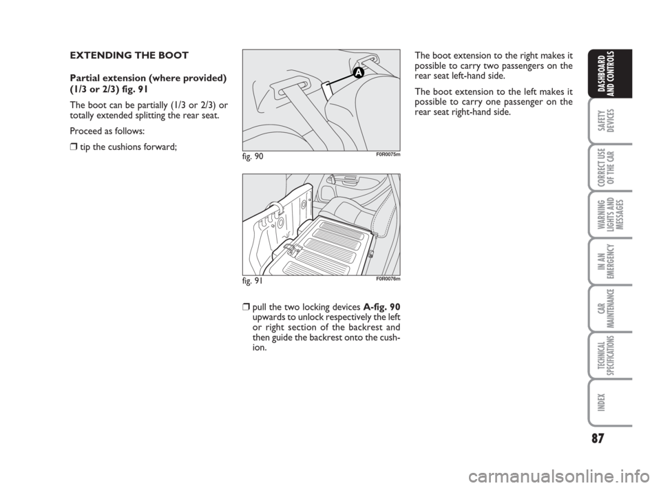
EXTENDING THE BOOT
Partial extension (where provided)
(1/3 or 2/3) fig. 91
The boot can be partially (1/3 or 2/3) or
totally extended splitting the rear seat.
Proceed as follows:
❒tip the cushions forward;fig. 90F0R0075m
fig. 91F0R0076m
❒pull the two locking devices A-fig. 90
upwards to unlock respectively the left
or right section of the backrest and
then guide the backrest onto the cush-
ion.The boot extension to the right makes it
possible to carry two passengers on the
rear seat left-hand side.
The boot extension to the left makes it
possible to carry one passenger on the
rear seat right-hand side.
044-090 LINEA 1ed GB 3-09-2008 17:29 Pagina 87
Page 89 of 234
88
SAFETY
DEVICES
CORRECT USE
OF THE
CAR
WARNING
LIGHTS AND
MESSAGES
IN AN
EMERGENCY
CAR
MAINTENANCE
TECHNICAL
SPECIFICATIONS
INDEX
DASHBOARD
AND CONTROLS
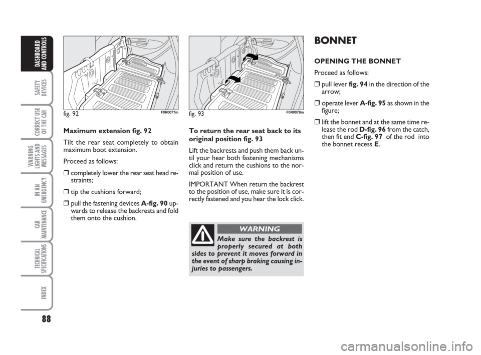
fig. 93F0R0078m
To return the rear seat back to its
original position fig. 93
Lift the backrests and push them back un-
til your hear both fastening mechanisms
click and return the cushions to the nor-
mal position of use.
IMPORTANT When return the backrest
to the position of use, make sure it is cor-
rectly fastened and you hear the lock click. Maximum extension fig. 92
Tilt the rear seat completely to obtain
maximum boot extension.
Proceed as follows:
❒completely lower the rear seat head re-
straints;
❒tip the cushions forward;
❒pull the fastening devices A-fig. 90up-
wards to release the backrests and fold
them onto the cushion.
fig. 92F0R0077m
Make sure the backrest is
properly secured at both
sides to prevent it moves forward in
the event of sharp braking causing in-
juries to passengers.
WARNING
BONNET
OPENING THE BONNET
Proceed as follows:
❒pull lever fig. 94in the direction of the
arrow;
❒operate lever A-fig. 95as shown in the
figure;
❒lift the bonnet and at the same time re-
lease the rod D-fig. 96from the catch,
then fit end C-fig. 97 of the rod into
the bonnet recess E.
044-090 LINEA 1ed GB 3-09-2008 17:29 Pagina 88