engine FIAT MAREA 2000 1.G Workshop Manual
[x] Cancel search | Manufacturer: FIAT, Model Year: 2000, Model line: MAREA, Model: FIAT MAREA 2000 1.GPages: 330
Page 143 of 330
Marea- Marea Weekend
2000 range ©
Electrical equipment
Control module
55.
The vehicle is fitted with numerous electronic
control units which have autodiagnostic func
tions.
When these control units are connected to di
agnostic equipment (Examiner or other in
struments) it is possible to read the autodiag
nostic information (parameters, errors) or carry
out active diagnosis.
On the version with EOBD (European On
Board Diagnosis) which conforms to Directive
98/69/CE (EURO 3), there is not an indi
vidual diagnostic socket for each control
unit, but a single.- standardized 16-way
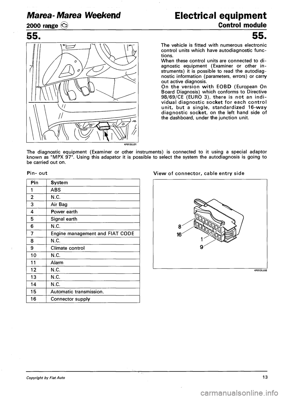
diagnostic socket, on the left hand side of
the dashboard, under the junction unit.
The diagnostic equipment (Examiner or other instruments) is connected to it using a special adaptor
known as "MPX 97". Using this adapator it is possible to select the system the autodiagnosis is going to
be carried out on.
Pin- out View of connector, cable entry side
Pin System
1 ABS
2 N.C.
3 Air Bag
4 Power earth
5 Signal earth
6 N.C.
7 Engine management and FIAT CODE
8 N.C.
9 Climate control
10 N.C.
11 Alarm
12 N.C.
13 N.C.
14 N.C.
15 Automatic transmission.
16 Connector supply
Copyright by Fiat Auto 13
Page 144 of 330
Electrical equipment
Instrument panel
Marea-Marea Weekend
2000 range ©
55.
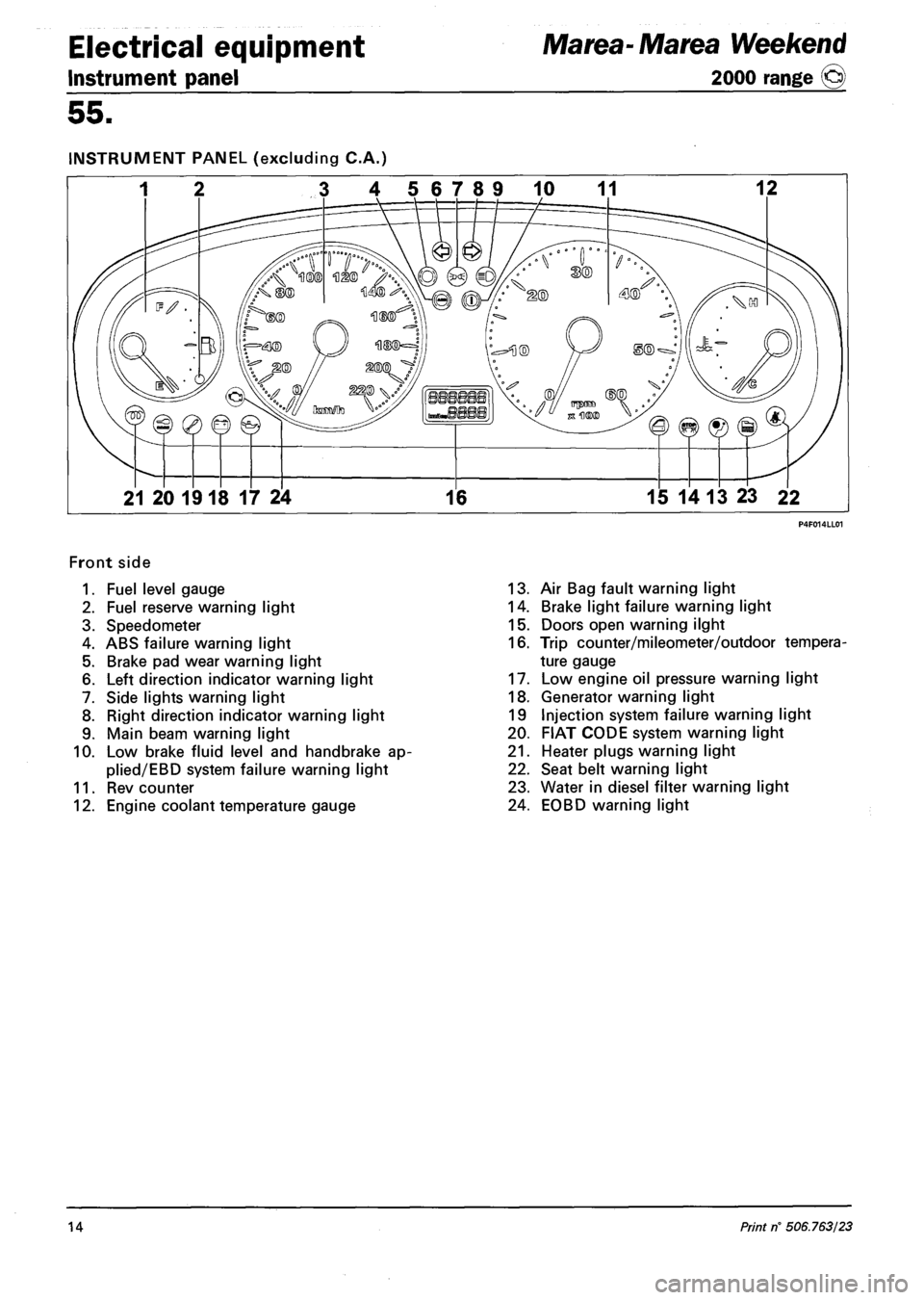
INSTRUMENT PANEL (excluding C.A.)
3 4 56789 10 11 12
21 20 1918 17 24 16 15 14 13 23 22
Front side
1. Fuel level gauge
2. Fuel reserve warning light
3. Speedometer
4. ABS failure warning light
5. Brake pad wear warning light
6. Left direction indicator warning light
7. Side lights warning light
8. Right direction indicator warning light
9. Main beam warning light
10. Low brake fluid level and handbrake ap-
plied/EBD system failure warning light
11. Rev counter
12. Engine coolant temperature gauge
13. Air Bag fault warning light
14. Brake light failure warning light
15. Doors open warning ilght
16. Trip counter/mileometer/outdoor tempera
ture gauge
17. Low engine oil pressure warning light
18. Generator warning light
19 Injection system failure warning light
20. FIAT CODE system warning light
21. Heater plugs warning light
22. Seat belt warning light
23. Water in diesel filter warning light
24. EOBD warning light
14 Print rf 506.763/23
Page 145 of 330
Marea- Marea Weekend
2000 range ©
Electrical equipment
Control module
55.
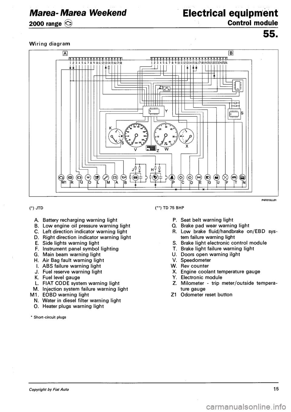
Wiring diagram
.mrmmmL 18 3 4 5 6 7 8 9 10 U 1213 1415161718 |TTTTrTrrrrTTTTT1.TTTTT1pmL 18 3 4 5 6 7 8 9 10 11 121314151617181920213223248586
n ti
O Mill
(*) JTD
A. Battery recharging warning light
B. Low engine oil pressure warning light
C. Left direction indicator warning light
D. Right direction indicator warning light
E. Side lights warning light
F. Instrument panel symbol lighting
G. Main beam warning light
H. Air Bag fault warning light
I. ABS failure warning light
J. Fuel reserve warning light
K. Fuel level gauge
L. FIAT CODE system warning light
M. Injection system failure warning light
M1. EOBD warning light
N. Water in diesel filter warning light
O. Heater plugs warning light
(**) TD 75 BHP
P. Seat belt warning light
Q. Brake pad wear warning light
R. Low brake fluid/handbrake on/EBD sys
tem failure warning light
S. Brake light electronic control module
T. Brake light failure warning light
U. Doors open warning ilght
V. Speedometer
W. Rev counter
X. Engine coolant temperature gauge
Y. Electronic module
Z. Milometer - trip meter/outside tempera
ture gauge
Z1 Odometer reset button
* Short-circuit plugs
Copyright by Fiat Auto 15
Page 146 of 330
Electrical equipment
Instrument panel
Marea- Marea Weekend
2000 range ©
55.
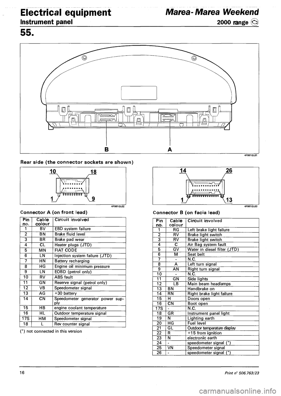
Rear side (the connector sockets are shown)
Connector A (on front lead) Connector B (on facia lead)
Pin no. Cable colour Circuit involved
1 BV EBD system failure
2 BN Brake fluid level
3 BR Brake pad wear
4 CL Heater plugs (JTD)
5 MN FIAT CODE
6 LN Injection system failure (JTD)
7 HN Battery recharging
8 HG Engine oil minimum pressure
9 LN EOBD (petrol only)
10 RV ABS fault
11 GN Reserve signal (petrol only)
12 VB Speedometer signal
13 AG +30 battery
14 CN Speedometer generator power supply
15 HB engine coolant temperature
16 HL Outdoor temperature signal
17S HM Speedometer signal
18 L Rev counter signal
(*) not connected in this version
Pin no. Cable colour Circuit involved
1 RG Left brake light failure
2 RV Brake light switch
3 RV Brake light switch
4 C Air Bag system fault
5 GV Water in diesel filter (JTD)
6 M Seat belt
7 -N.C.
8 A Left turn signal
9 AN Right turn signal
10 -N.C.
11 GN Side lights
12 LB Main beam headlamps
13 BN Handbrake on
14 RN Right brake light failure
15 H Doors open
16 CN Boot open
17S -N.C.
18 GR Instrument panel light
19 N Lighting earth
20 HG Fuel level
21 GL Outdoor temperature display
22 R +15 from ignition
23 N electronic earth
24 -speedometer signal (*)
25 VN Speedometer signal
26 -speedometer signal (*)
16 Print n° 506.763/23
Page 147 of 330
Marea- Marea Weekend Electrical equipment
2000 range (Q) Control module
55.
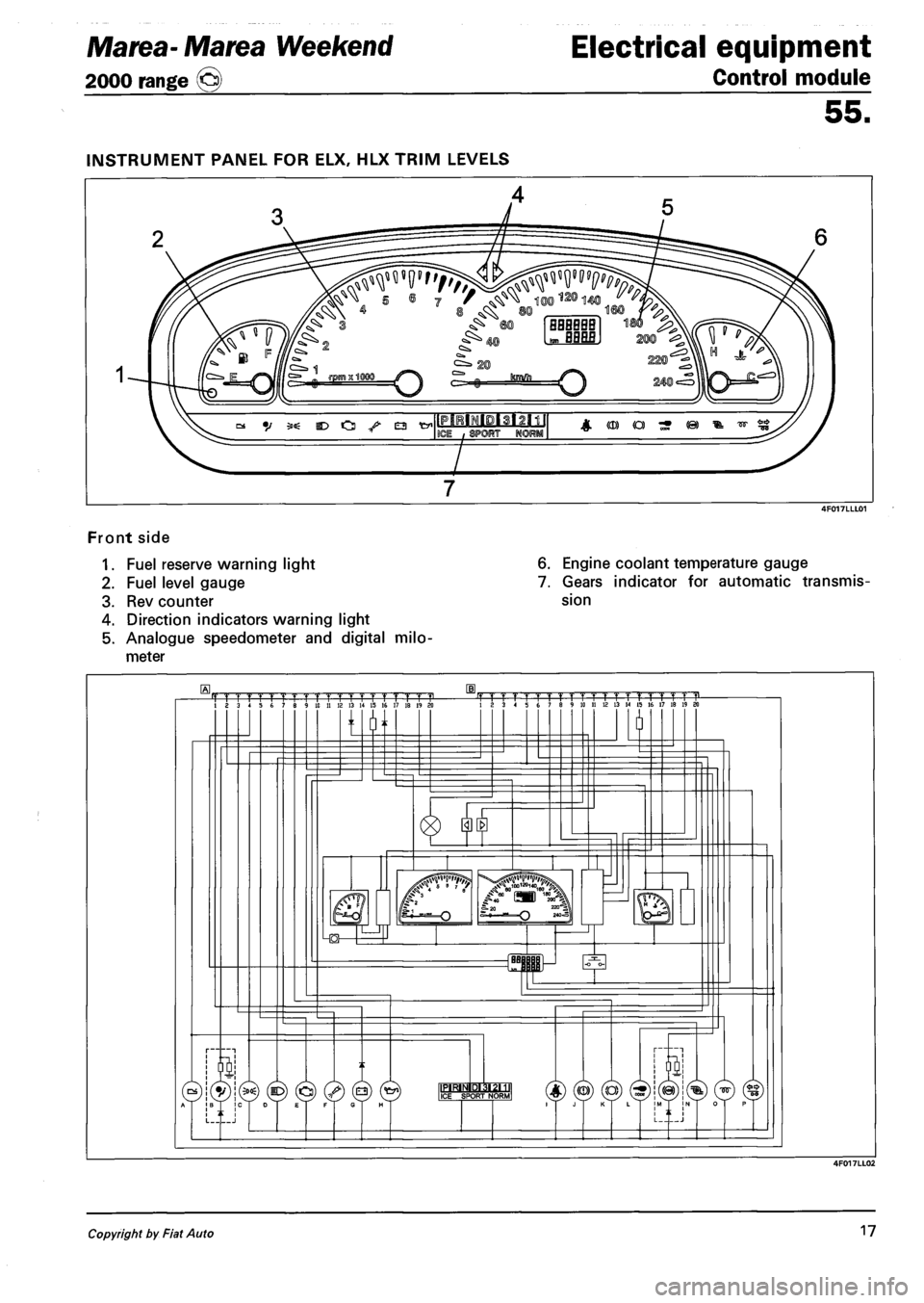
Front side
1. Fuel reserve warning light
2. Fuel level gauge
3. Rev counter
4. Direction indicators warning light
5. Analogue speedometer and digital milo
meter
6. Engine coolant temperature gauge
7. Gears indicator for automatic transmis
sion
Copyright by Fiat Auto 17
Page 163 of 330
Marea- Marea Weekend
2000 range @
Electrical system
Radio System
55.
OPERATION
ON/OFF
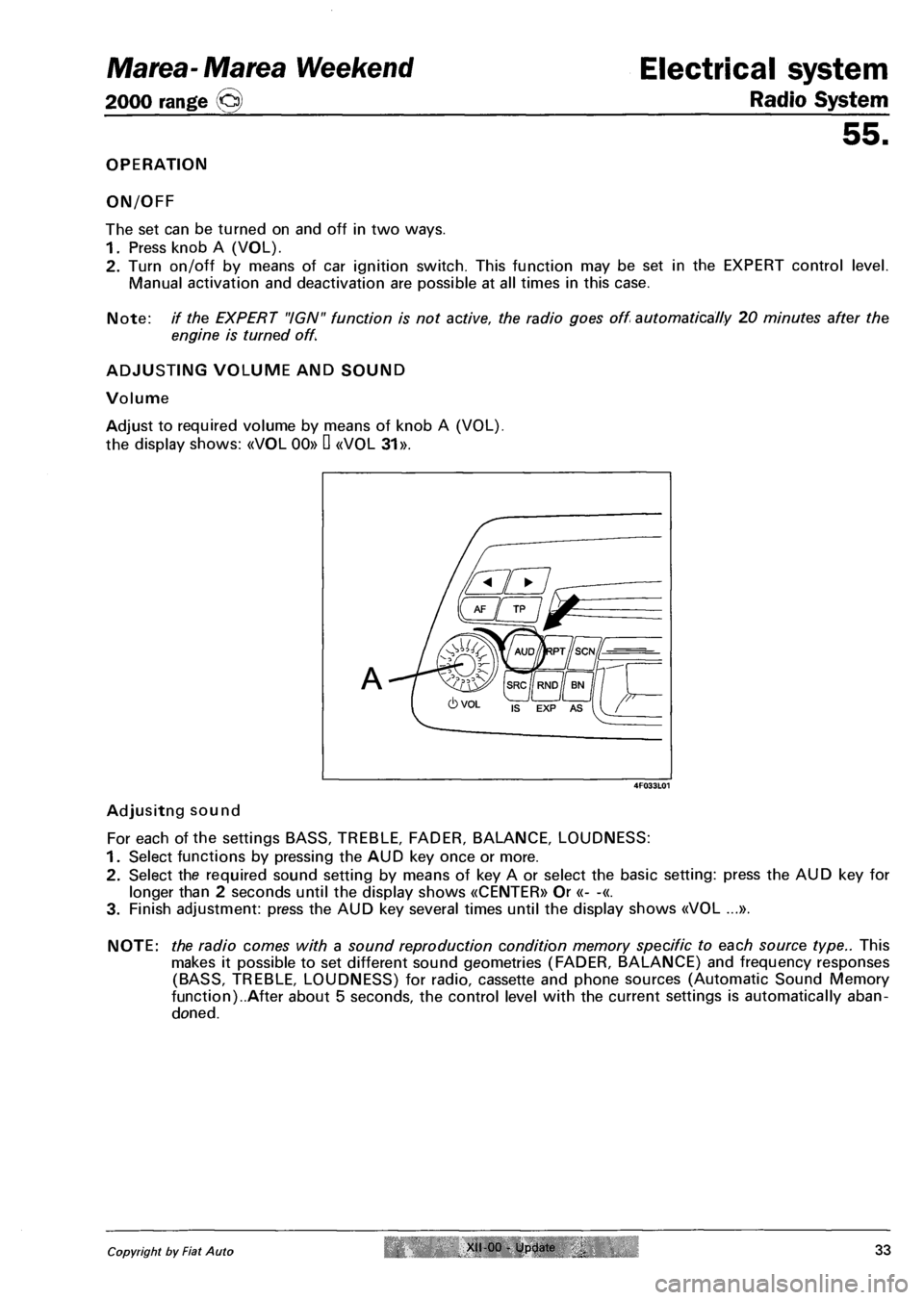
The set can be turned on and off in two ways.
1. Press knob A (VOL).
2. Turn on/off by means of car ignition switch. This function may be set in the EXPERT control level.
Manual activation and deactivation are possible at all times in this case.
Note: // the EXPERT "IGN" function is not active, the radio goes off automatically 20 minutes after the
engine is turned off.
ADJUSTING VOLUME AND SOUND
Volume
Adjust to required volume by means of knob A (VOL),
the display shows: «VOL 00» D «V0L 31».
Adjusitng sound
For each of the settings BASS, TREBLE, FADER, BALANCE, LOUDNESS:
1. Select functions by pressing the AUD key once or more.
2. Select the required sound setting by means of key A or select the basic setting: press the AUD key for
longer than 2 seconds until the display shows «CENTER» Or «- -«.
3. Finish adjustment: press the AUD key several times until the display shows «V0L ...».
NOTE: the radio comes with a sound reproduction condition memory specific to each source type.. This
makes it possible to set different sound geometries (FADER, BALANCE) and frequency responses
(BASS, TREBLE, LOUDNESS) for radio, cassette and phone sources (Automatic Sound Memory
function)..After about 5 seconds, the control level with the current settings is automatically aban
doned.
Copyright by Fiat Auto XII 00 - Update 33
4F033L01
Page 173 of 330
Marea-Marea Weekend Electrical system
2000 range (§j) Radio System
55.
10 - suppression of sound in case of incoming/outgoing phone call
- turn volume knob clockwise: «PHONE 0FF» no use of phone connection
- turn volume knob clockwise: «PH0NE 0N»: the radio sound is automatically deactivated in the case of
a phone call
The «PH0NE ON" function required the mobile phone mount base to be connected.
The «PH0NE IN» function allows a conversation via the car speakers in the case of a phone call.
The «PH0NE IN» function requires the mobile phone to be connected in handsfree mode
If the radio is off, a phone call (IN or OUT) is still possible. In this case the radio
- comes on automatically;
- allows listening under sound conditions identical to the last phone call (BASS, TREBLE, FADER,
BALANCE);
- goes off automatically at the end of the phone call
11 - setting mobile phone input sensitivity
Allows adaptation to the signal broadcast level for the type of handsfree system installed.
- turn volume knob anticlockwise: «PHONE 00» : low input sensitivity
- turn volume knob clockwise: «PHONE 03»: high input sensitivity
12 - security code activation
The code is not activated if «CODE» appears on the display.
If «SAFE» appears on the display, the code is activated.
NOTE: See next section for more detailed instructions.
13 - Controlling volume according to vehicle speed (SCV)
Standard value: «SCVOL 19»
Function off: «SCVOL - -«
Function at maximum efficiency: «SCVOL 34»
Setting:
1. Vehicle still, engine on: set required volume using the relevant knob.
2. Depress the EXP key for more than 2 seconds until «EXPERT» appears on the display.
3. Use keys A or B to select the «SCVOL» setting.
4. Set the required value using the volume knob:
- turn volume knob clockwise: VOL +
- turn volume knob anticlockwise: VOL -
14 - audible function confirmation (BEEP)
The BEEP function is active in the system
This function gives an audible confirmation (BEEP) of the functions. Function activation requires continu
ous pressing of the key for a time greater than or equal to 2 seconds.
15 - select MONO/STEREO radio reproduction
turn volume knob clockwise: «MONO ON».
turn volume knob anticlockwise: «MONO OFF».
16 - activate/deactivate LOC
The automatic search in the FM range may be used at two sensitivity levels When in search of stations,
the set may be tuned with high field intensity (local stations) or low field intensity (distant reception).
- turn volume knob clockwise: «LOC ON».
- turn volume knob anticlockwise: «LOC OFF».
Copyright by Fiat Auto XII-00 Updale 43
Page 185 of 330
Electrical system Marea-Marea Weekend
Wiring diagrams 2000 range (jcj)
55.
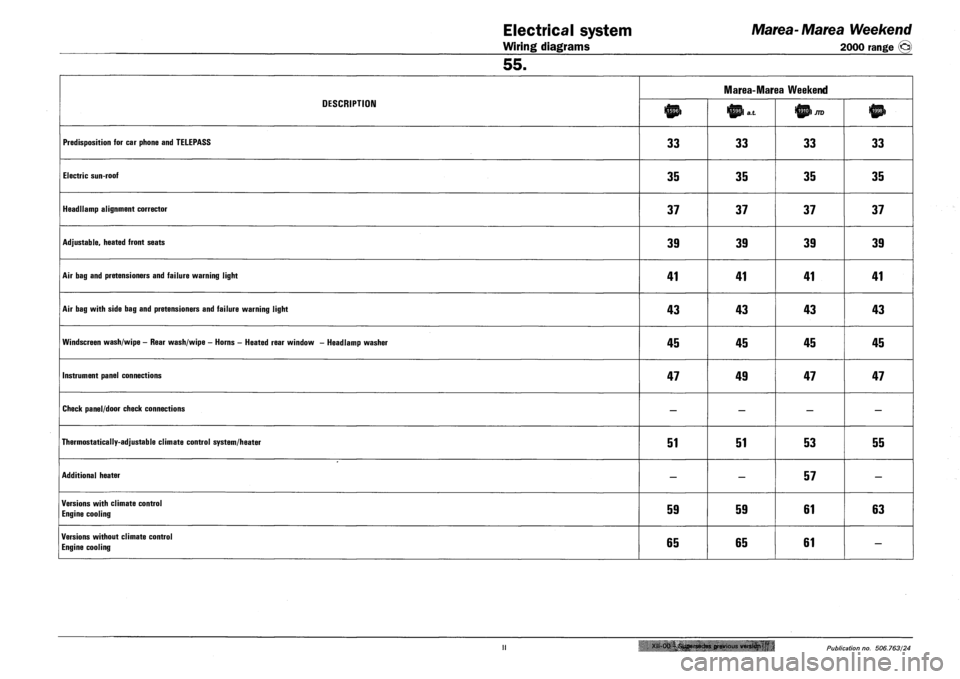
DESCRIPTION
Marea-Marea Weekend
DESCRIPTION lnp> Ittpl a.t
PREDISPOSITION FOR CAR PHONE AND TELEPASS 33 33 33 33
ELECTRIC SUN-ROOF 35 35 35 35
HEADLLAMP ALIGNMENT CORRECTOR 37 37 37 37
ADJUSTABLE, HEATED FRONT SEATS 39 39 39 39
AIR BAG AND PRETENSIONERS AND FAILURE WARNING LIGHT 41 41 41 41
AIR BAG WITH SIDE BAG AND PRETENSIONERS AND FAILURE WARNING LIGHT 43 43 43 43
WINDSCREEN WASH/WIPE - REAR WASH/WIPE - HORNS - HEATED REAR WINDOW - HEADLAMP WASHER 45 45 45 45
INSTRUMENT PANEL CONNECTIONS 47 49 47 47
CHECK PANEL/DOOR CHECK CONNECTIONS — — — —
THERMOSTATICALLY-ADJUSTABLE CLIMATE CONTROL SYSTEM/HEATER 51 51 53 55
ADDITIONAL HEATER — — 57 —
VERSIONS WITH CLIMATE CONTROL
ENGINE COOLING 59 59 61 63
VERSIONS WITHOUT CLIMATE CONTROL
ENGINE COOLING 65 65 61 —
Xll-Oa-i.Supersedes previous version 'u • Publication no. 506.763/24
Page 186 of 330
Marea-Marea Weekend Electrical equipment
2000 range (§) Wiring diagrams
55.
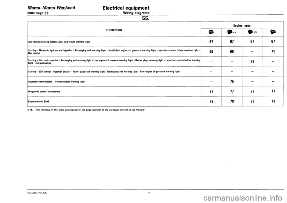
DESCRIPTION
Engine types
DESCRIPTION 10i 0) c.a. 01/70
ANTI-LOCKING BRAKING SYSTEM (ABS) AND FAILURE WARNING LIGHT 67 67 67 67
STARTING - ELECTRONIC IGNITION AND INJECTION - RECHARGING AND WARNING LIGHT - INSUFFICIENT ENGINE OIL PRESSURE WARNING LIGHT - INJECTION SYSTEM FAILURE WARNING LIGHT -
REV COUNTER 69 69 — 71
STARTING - ELECTRONIC INJECTION - RECHARGING AND WARNING LIGHT - LOW ENGINE OIL PRESSURE WARNING LIGHT - HEATER PLUGS WARNING LIGHT - INJECTION SYSTEM FAILURE WARNING
LIGHT - FUEL PREHEATING — — 73 —
STARTING - EGR CONTROL - INJECTION CONTROL - HEATER PLUGS AND WARNING LIGHT - RECHARGING AND WARNING LIGHT - LOW ENGINE OIL PRESSURE WARNING LIGHT — — — —
AUTOMATIC TRANSMISSION - SYSTEM FAILURE WARNING LIGHT — 75 — —
DIAGNOSTIC SOCKECT CONNECTIONS 77 77 77 77
PREPARATION FOR TAXI 79 79 79 79
FM.B. The numbers in the table correspond to the page number of the electrical system in the manual
Copyright by Fiat Auto III
Page 187 of 330
Marea- Marea Weekend
2000 range ©
Electrical equipment
Wiring diagrams
55.
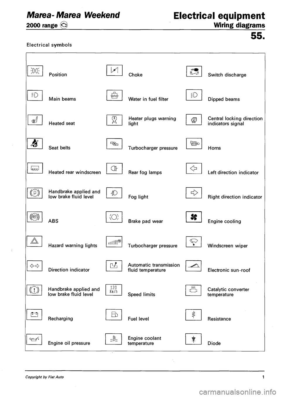
Electrical symbols
M
Lt3
Position
Main beams
Heated seat
Seat belts
Heated rear windscreen
Handbrake applied and
low brake fluid level
ABS
Hazard warning lights
Direction indicator
Handbrake applied and
low brake fluid level
Recharging
Engine oil pressure
IX!
(O)
Hum®
120 Km/h
Choke
Water in fuel filter
Heater plugs warning
light
Turbocharger pressure
Rear fog lamps
Fog light
Brake pad wear
Turbocharger pressure
Automatic transmission
fluid temperature
Speed limits
Fuel level
Engine coolant
temperature
to
Switch discharge
Dipped beams
Central locking direction
indicators signal
Horns
Left direction indicator
Right direction indicator
Engine cooling
Windscreen wiper
Electronic sun-roof
Catalytic converter
temperature
Resistance
Diode
Copyright by Fiat Auto 1