engine FIAT MAREA 2000 1.G Owners Manual
[x] Cancel search | Manufacturer: FIAT, Model Year: 2000, Model line: MAREA, Model: FIAT MAREA 2000 1.GPages: 330
Page 114 of 330
Engine Marea- Marea Weekend IP ™
Fuel feed system 2000 range o
10.
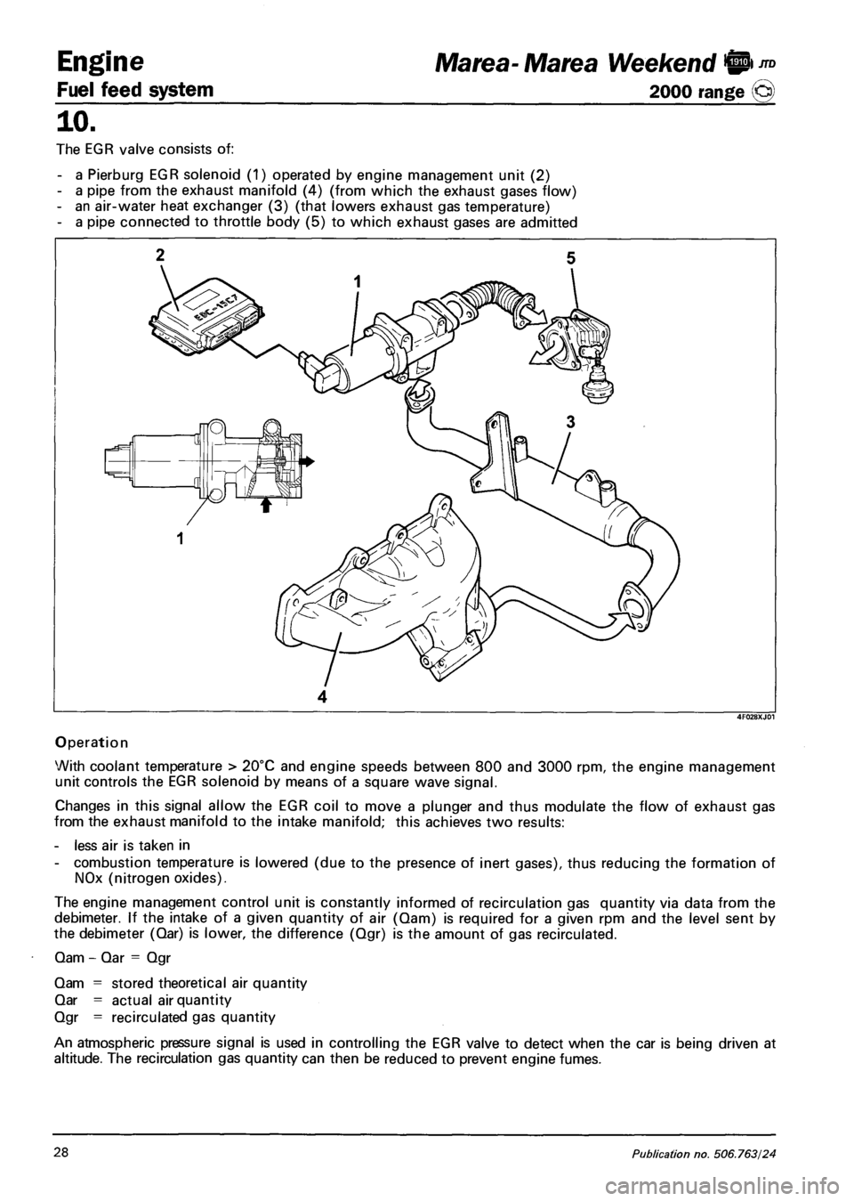
The EGR valve consists of:
- a Pierburg EGR solenoid (1) operated by engine management unit (2)
- a pipe from the exhaust manifold (4) (from which the exhaust gases flow)
- an air-water heat exchanger (3) (that lowers exhaust gas temperature)
- a pipe connected to throttle body (5) to which exhaust gases are admitted
4
Operation
With coolant temperature > 20°C and engine speeds between 800 and 3000 rpm, the engine management
unit controls the EGR solenoid by means of a square wave signal.
Changes in this signal allow the EGR coil to move a plunger and thus modulate the flow of exhaust gas
from the exhaust manifold to the intake manifold; this achieves two results:
- less air is taken in
- combustion temperature is lowered (due to the presence of inert gases), thus reducing the formation of
NOx (nitrogen oxides).
The engine management control unit is constantly informed of recirculation gas quantity via data from the
debimeter. If the intake of a given quantity of air (Qam) is required for a given rpm and the level sent by
the debimeter (Qar) is lower, the difference (Qgr) is the amount of gas recirculated.
Qam - Qar = Qgr
Qam = stored theoretical air quantity
Qar = actual air quantity
Qgr = recirculated gas quantity
An atmospheric pressure signal is used in controlling the EGR valve to detect when the car is being driven at
altitude. The recirculation gas quantity can then be reduced to prevent engine fumes.
28 Publication no. 506.763/24
Page 115 of 330
Marea-Marea Weekend
2000 range (j§)
1
4F029XJ02
Engine
Fuel feed system
10.
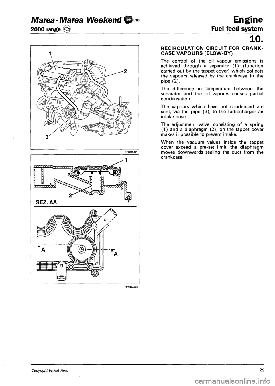
RECIRCULATION CIRCUIT FOR CRANK-
CASE VAPOURS (BLOW-BY)
The control of the oil vapour emissions is
achieved through a separator (1) (function
carried out by the tappet cover) which collects
the vapours released by the crankcase in the
pipe (2).
The difference in temperature between the
separator and the oil vapours causes partial
condensation.
The vapours which have not condensed are
sent, via the pipe (3), to the turbocharger air
intake hose.
The adjustment valve, consisting of a spring
(1) and a diaphragm (2), on the tappet cover
makes it possible to prevent intake.
When the vacuum values inside the tappet
cover exceed a pre-set limit, the diaphragm
moves downwards sealing the duct from the
crankcase.
Copyright by Fiat Auto 29
Page 116 of 330
Engine
Fuel feed system
Marea-Marea Weekend
2000 range ©
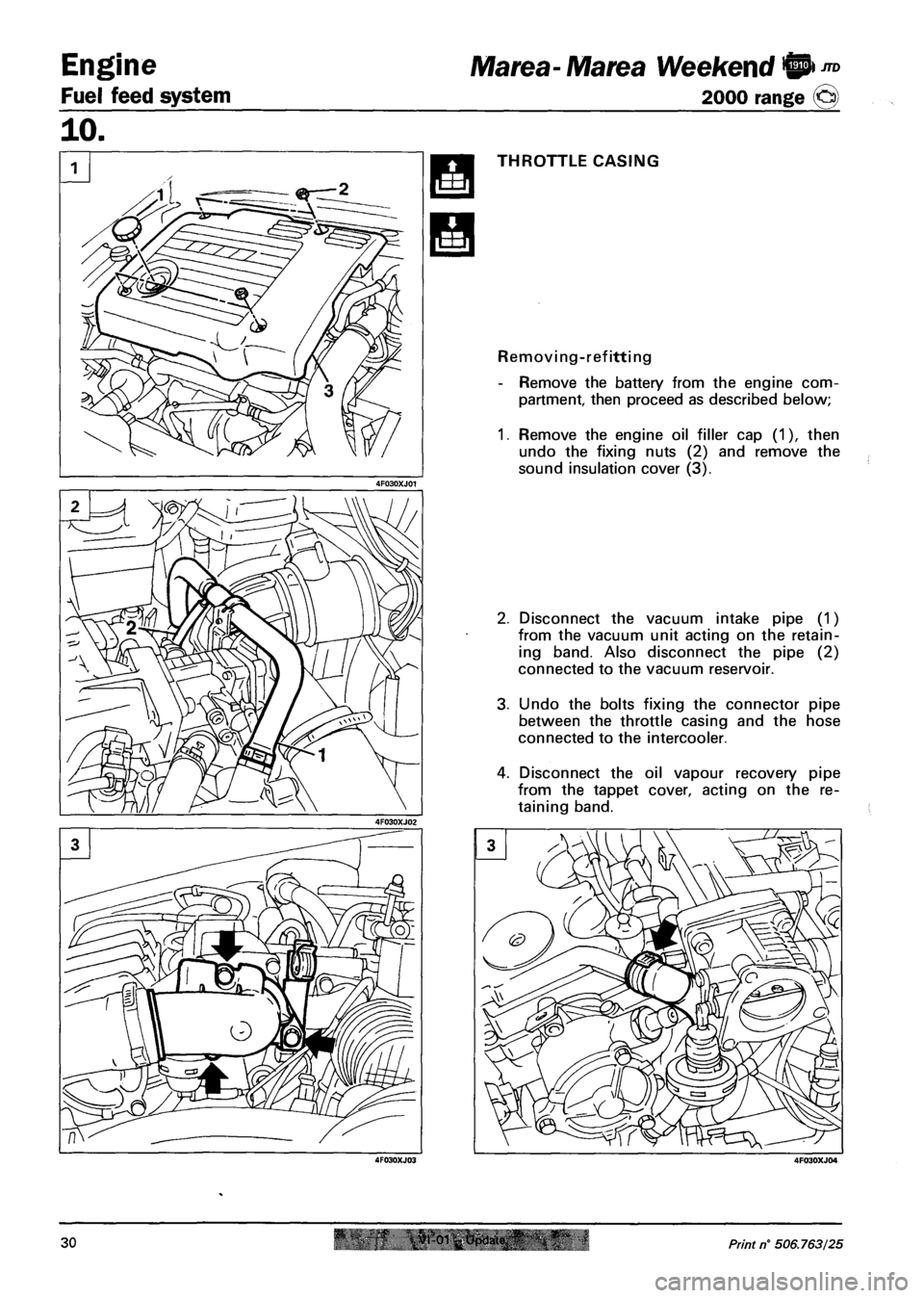
THROTTLE CASING
Removing-refitting
- Remove the battery from the engine com
partment, then proceed as described below;
1. Remove the engine oil filler cap (1), then
undo the fixing nuts (2) and remove the
sound insulation cover (3).
2. Disconnect the vacuum intake pipe (1)
from the vacuum unit acting on the retain
ing band. Also disconnect the pipe (2)
connected to the vacuum reservoir.
3. Undo the bolts fixing the connector pipe
between the throttle casing and the hose
connected to the intercooler.
4. Disconnect the oil vapour recovery pipe
from the tappet cover, acting on the re
taining band.
30 Print n° 506.763/25
Page 117 of 330
Marea- Marea Weekend 9 *°
2000 range @)
Engine
Fuel feed system
10.
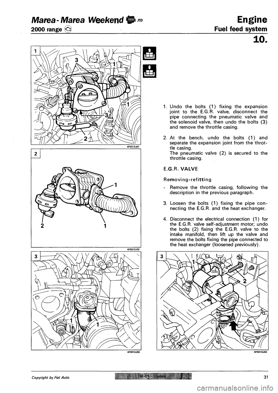
1. Undo the bolts (1) fixing the expansion
joint to the E.G.R. valve, disconnect the
pipe connecting the pneumatic valve and
the solenoid valve, then undo the bolts (3)
and remove the throttle casing.
2. At the bench, undo the bolts (1) and
separate the expansion joint from the throt
tle casing.
The pneumatic valve (2) is secured to the
throttle casing.
E.G.R. VALVE
Removing-refitting
- Remove the throttle casing, following the
description in the previous paragraph.
3. Loosen the bolts (1) fixing the pipe con
necting the E.G.R. and the heat exchanger.
4. Disconnect the electrical connection (1) for
the E.G.R. valve self-adjustment motor; undo
the bolts (2) fixing the E.G.R. valve to the
intake manifold, then lift up the valve and
remove the bolts fixing the pipe connected to
the heat exchanger (loosened previously).
Copyright by Fiat Auto VI 01 i ndate 31
Page 118 of 330
Engine
Fuel feed system
JTD Marea-Marea Weekend 9
2000 range ©
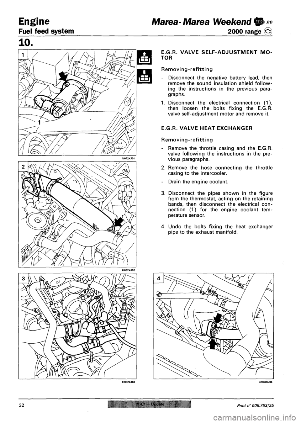
E.G.R.
TOR
VALVE SELF-ADJUSTMENT MO-
Removing-refitting
- Disconnect the negative battery lead, then
remove the sound insulation shield follow
ing the instructions in the previous para
graphs.
1. Disconnect the electrical connection (1),
then loosen the bolts fixing the E.G.R.
valve self-adjustment motor and remove it.
E.G.R. VALVE HEAT EXCHANGER
Removi ng - ref itti ng
- Remove the throttle casing and the E.G.R.
valve following the instructions in the pre
vious paragraphs.
2. Remove the hose connecting the throttle
casing to the intercooler.
- Drain the engine coolant.
3. Disconnect the pipes shown in the figure
from the thermostat, acting on the retaining
bands, then disconnect the electrical con
nection (1) for the engine coolant tem
perature sensor.
4. Undo the bolts fixing the heat exchanger
pipe to the exhaust manifold.
32 0"" Und«r 4 Print n° 506.763/25
Page 119 of 330
Marea- Marea Weekend 9
2000 range ©
Engine
Fuel feed system
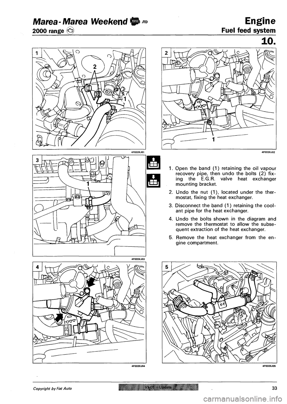
Open the band (1) retaining the oil vapour
recovery pipe, then undo the bolts (2) fix
ing the E.G.R. valve heat exchanger
mounting bracket.
Undo the nut (1), located under the ther
mostat, fixing the heat exchanger.
Disconnect the band (1) retaining the cool
ant pipe for the heat exchanger.
Undo the bolts shown in the diagram and
remove the thermostat to allow the subse
quent extraction of the heat exchanger.
Remove the heat exchanger from the en
gine compartment.
Copyright by Fiat Auto VK01 - Update ,f 33
Page 120 of 330
Engine
Fuel feed system
Marea- Marea Weekend 9 ™
2000 range ©
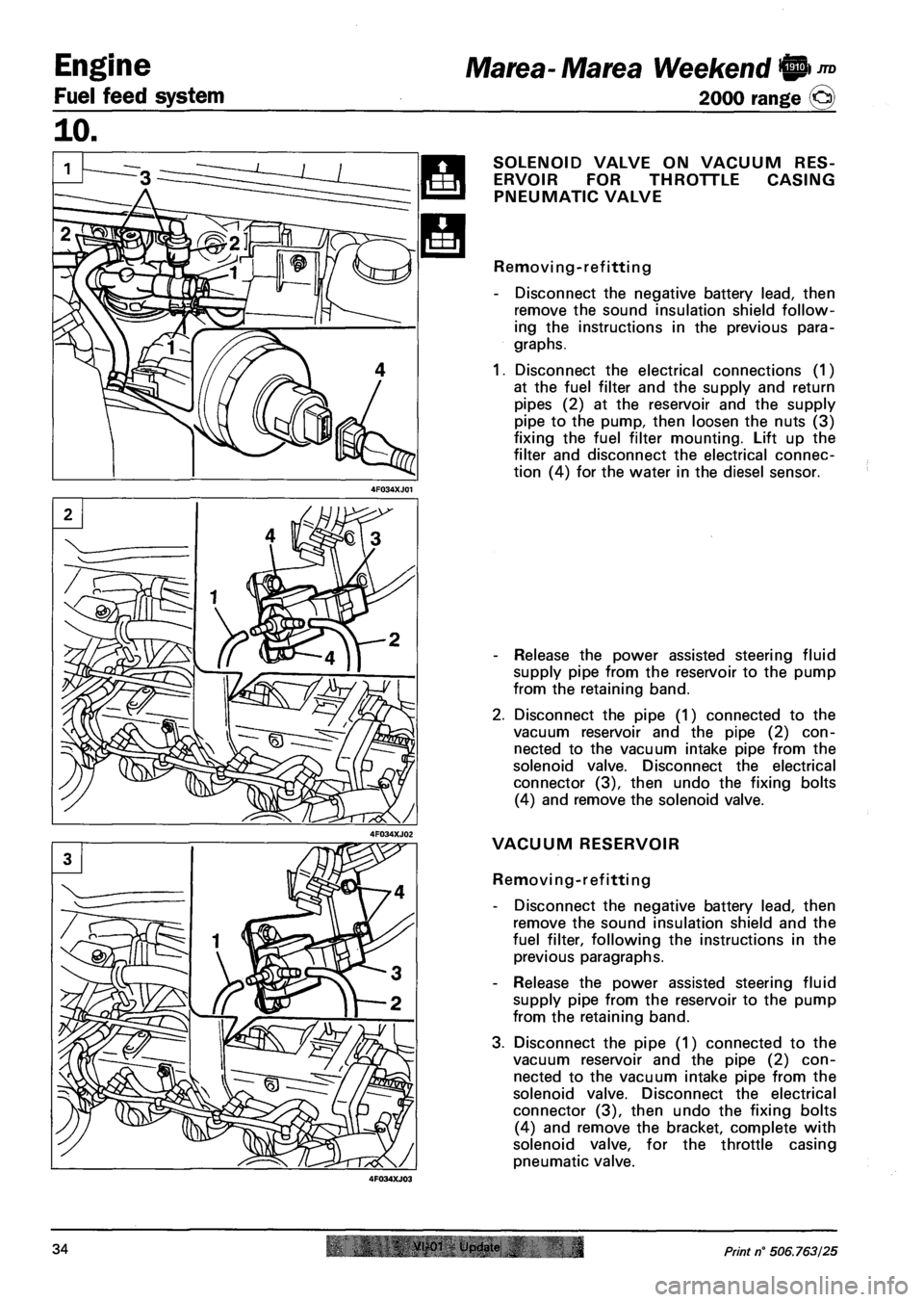
SOLENOID VALVE ON VACUUM RES
ERVOIR FOR THROTTLE CASING
PNEUMATIC VALVE
Removing-refitting
- Disconnect the negative battery lead, then
remove the sound insulation shield follow
ing the instructions in the previous para
graphs.
1. Disconnect the electrical connections (1)
at the fuel filter and the supply and return
pipes (2) at the reservoir and the supply
pipe to the pump, then loosen the nuts (3)
fixing the fuel filter mounting. Lift up the
filter and disconnect the electrical connec
tion (4) for the water in the diesel sensor.
- Release the power assisted steering fluid
supply pipe from the reservoir to the pump
from the retaining band.
2. Disconnect the pipe (1) connected to the
vacuum reservoir and the pipe (2) con
nected to the vacuum intake pipe from the
solenoid valve. Disconnect the electrical
connector (3), then undo the fixing bolts
(4) and remove the solenoid valve.
VACUUM RESERVOIR
Removing-refitting
- Disconnect the negative battery lead, then
remove the sound insulation shield and the
fuel filter, following the instructions in the
previous paragraphs.
- Release the power assisted steering fluid
supply pipe from the reservoir to the pump
from the retaining band.
3. Disconnect the pipe (1) connected to the
vacuum reservoir and the pipe (2) con
nected to the vacuum intake pipe from the
solenoid valve. Disconnect the electrical
connector (3), then undo the fixing bolts
(4) and remove the bracket, complete with
solenoid valve, for the throttle casing
pneumatic valve.
34 VI-01 Update IN Print n° 506.763/25
Page 121 of 330
Ma tea- Marea Weekend 9 m
2000 range ©)
Engine
Fuel feed system
10.
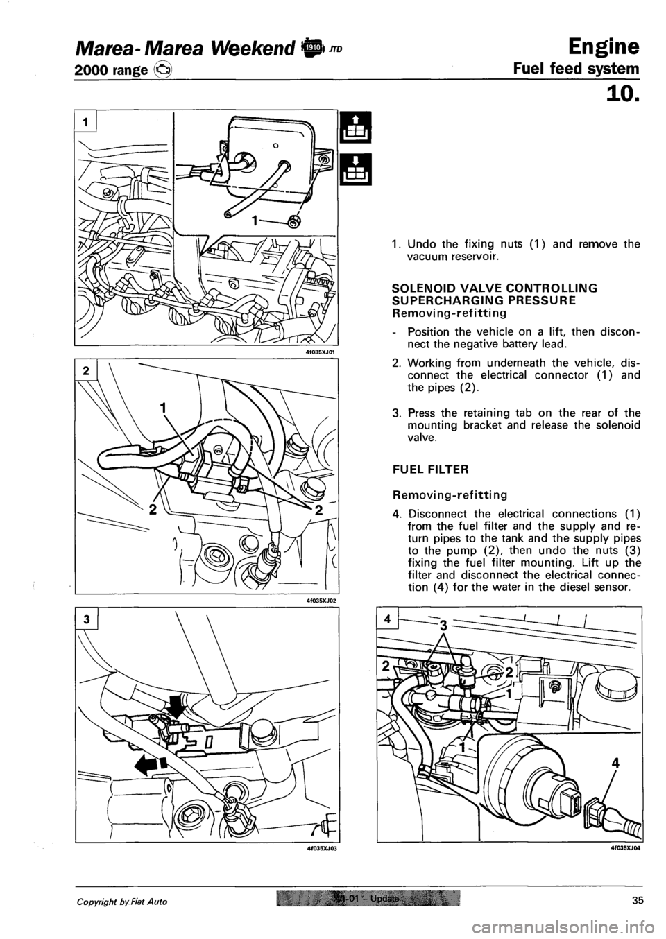
1. Undo the fixing nuts (1) and remove the
vacuum reservoir.
SOLENOID VALVE CONTROLLING
SUPERCHARGING PRESSURE
Removing-refitting
- Position the vehicle on a lift, then discon
nect the negative battery lead.
2. Working from underneath the vehicle, dis
connect the electrical connector (1) and
the pipes (2).
3. Press the retaining tab on the rear of the
mounting bracket and release the solenoid
valve.
FUEL FILTER
Removing-refitting
4. Disconnect the electrical connections (1)
from the fuel filter and the supply and re
turn pipes to the tank and the supply pipes
to the pump (2), then undo the nuts (3)
fixing the fuel filter mounting. Lift up the
filter and disconnect the electrical connec
tion (4) for the water in the diesel sensor.
Copyright by Fiat Auto oi upjdin 35
Page 122 of 330
Engine
Fuel feed system
Marea- Marea Weekend @ ™
2000 range ©
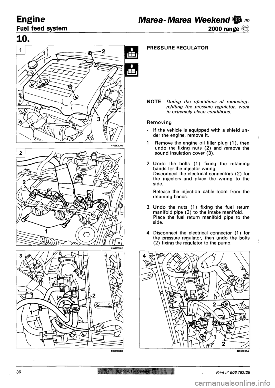
PRESSURE REGULATOR
NOTE During the operations of removing-
refitting the pressure regulator, work
in extremely clean conditions.
Removing
- If the vehicle is equipped with a shield un
der the engine, remove it.
1. Remove the engine oil filler plug (1), then
undo the fixing nuts (2) and remove the
sound insulation cover (3).
2. Undo the bolts (1) fixing the retaining
bands for the injector wiring.
Disconnect the electrical connectors (2) for
the injectors and place the wiring to the
side.
- Release the injection cable loom from the
retaining bands.
3. Undo the nuts (1) fixing the fuel return
manifold pipe (2) to the intake manifold.
Place the fuel return manifold pipe to the
side.
4. Disconnect the electrical connector (1) for
the pressure regulator, then undo the bolts
(2) fixing the regulator to the pump.
36 Print n° 506.763/25
Page 123 of 330
Marea-Marea Weekend H nD Engine
2000 range (Q) Fuel feed system
10.
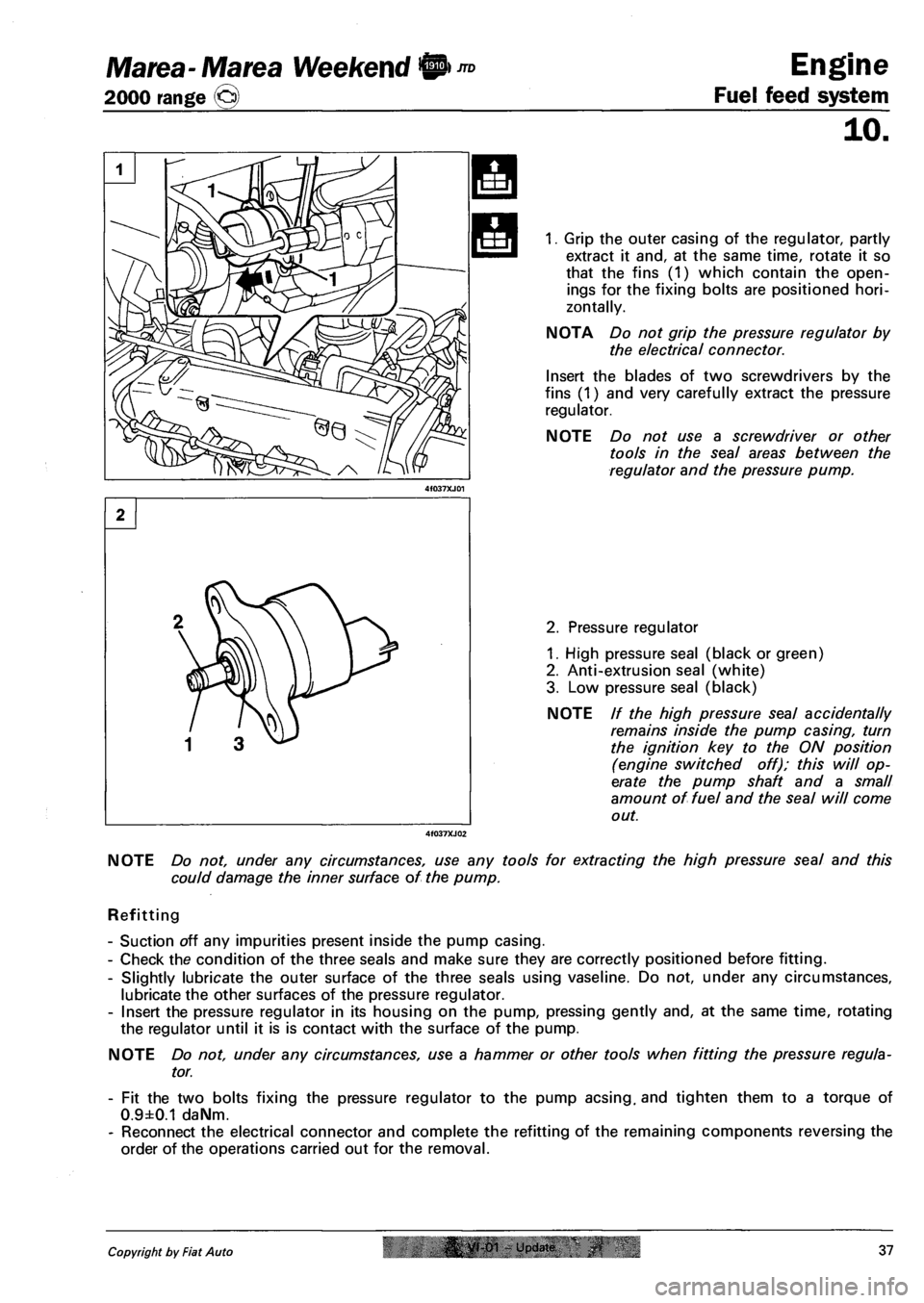
1. Grip the outer casing of the regulator, partly
extract it and, at the same time, rotate it so
that the fins (1) which contain the open
ings for the fixing bolts are positioned hori
zontally.
NOTA Do not grip the pressure regulator by
the electrical connector.
Insert the blades of two screwdrivers by the
fins (1) and very carefully extract the pressure
regulator.
NOTE Do not use a screwdriver or other
tools in the seal areas between the
regulator and the pressure pump.
2. Pressure regulator
1. High pressure seal (black or green)
2. Anti-extrusion seal (white)
3. Low pressure seal (black)
NOTE // the high pressure seal accidentally
remains inside the pump casing, turn
the ignition key to the ON position
(engine switched off); this will op
erate the pump shaft and a small
amount of fuel and the seal will come
out.
NOTE Do not, under any circumstances, use any tools for extracting the high pressure seal and this
could damage the inner surface of the pump.
Refitting
- Suction off any impurities present inside the pump casing.
- Check the condition of the three seals and make sure they are correctly positioned before fitting.
- Slightly lubricate the outer surface of the three seals using vaseline. Do not, under any circumstances,
lubricate the other surfaces of the pressure regulator.
- Insert the pressure regulator in its housing on the pump, pressing gently and, at the same time, rotating
the regulator until it is is contact with the surface of the pump.
NOTE Do not, under any circumstances, use a hammer or other tools when fitting the pressure regula
tor.
- Fit the two bolts fixing the pressure regulator to the pump acsing. and tighten them to a torque of
0.9±0.1 daNm.
- Reconnect the electrical connector and complete the refitting of the remaining components reversing the
order of the operations carried out for the removal.
Copyright by Fiat Auto |& yt-01 - Update 37