Ses FIAT MAREA 2000 1.G User Guide
[x] Cancel search | Manufacturer: FIAT, Model Year: 2000, Model line: MAREA, Model: FIAT MAREA 2000 1.GPages: 330
Page 98 of 330
Engine
Fuel feed system
10.
4F012XJ03
Marea- Matea Weekend 9 ™
2000 range (Q)
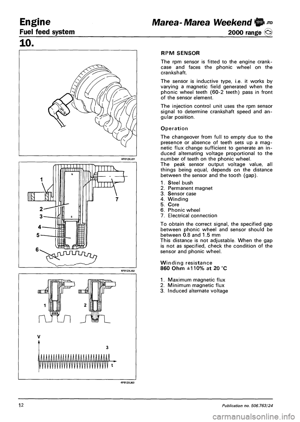
RPM SENSOR
The rpm sensor is fitted to the engine crank-
case and faces the phonic wheel on the
crankshaft.
The sensor is inductive type, i.e. it works by
varying a magnetic field generated when the
phonic wheel teeth (60-2 teeth) pass in front
of the sensor element.
The injection control unit uses the rpm sensor
signal to determine crankshaft speed and an
gular position.
Operation
The changeover from full to empty due to the
presence or absence of teeth sets up a mag
netic flux change sufficient to generate an in
duced alternating voltage proportional to the
number of teeth on the phonic wheel.
The peak sensor output voltage value, all
things being equal, depends on the distance
between the sensor and the tooth (gap).
1. Steel bush
2. Permanent magnet
3. Sensor case
4. Winding
5. Core
6. Phonic wheel
7. Electrical connection
To obtain the correct signal, the specified gap
between phonic wheel and sensor should be
between 0.8 and 1.5 mm
This distance is not adjustable. When the gap
is not as specified, check the condition of the
sensor and phonic wheel.
Winding resistance
860 Ohm ±110% at 20 °C
1. Maximum magnetic flux
2. Minimum magnetic flux
3. Induced alternate voltage
12 Publication no, 506.763/24
Page 99 of 330
Marea- Marea Weekend 9"°
2000 range ©
Engine
Fuel feed system
10.
TIMING SENSOR
The Hall effect sensor is fitted to the cylinder head and faces the camshaft pulley.
An opening on the pulley allows the timing sensor to detect the engine timing position and indicate it to
the injection control unit.
The injection control unit uses the timing sensor signal to detect TDC at the end of compression.
Operation
A semi-condulator layer, through which a current passes, immersed in a magnetic field (lines of force per
pendicular to the direction of the current), produces a difference in power, known as Hall voltage.
If the intensity of the current remains constant, the voltage produced only depends on the intensity of the
magnetic field. The intensity of the field can simply be altered periodically to produce a modulated electri
cal signal. Signal frequency is proportional to the speed with which the magnetic field changes.
To achieve this change, the sensor is crossed by a metal ring (inner part of the pulley) with an opening.
When it moves, the metal part of the ring covers the sensor to magnetic field and the output signal is
therefore low; Conversely, the sensor generates a high signal at the opening when the magnetic field is
present.
This signal, together with the rpm and TDC signals, allows the injection control unit to identify piston po
sition and determine injection point.
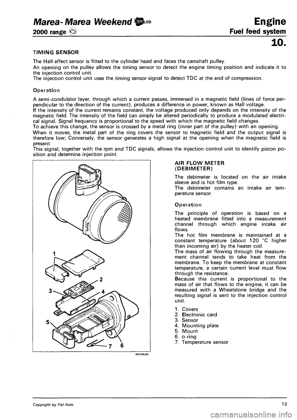
AIR FLOW METER
(DEBIMETER)
The debimeter is located on the air intake
sleeve and is hot film type.
The debimeter contains an intake air tem
perature sensor.
Operation
The principle of operation is based on a
heated membrane fitted into a measurement
channel through which engine intake air
flows.
The hot film membrane is maintained at a
constant temperature (about 120 °C higher
than incoming air) by the heater coil.
The mass of air flowing through the measure
ment channel tends to take heat from the
membrane. To keep the membrane at constant
temperature, a certain current level must flow
through the resistance.
Because this current is proportional to the
mass of air that flows to the engine, it can be
measured with a Wheatstone bridge and the
resulting signal is sent to the injection control
unit.
1. Covers
2. Electronic card
3. Sensor
4. Mounting plate
5. Mount
6. o-ring
7. Temperature sensor
Copyright by Fiat Auto 13
Page 100 of 330
Engine
Fuel feed system
10.
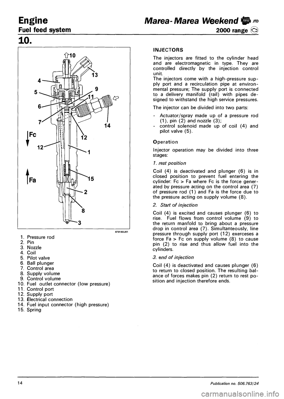
1. Pressure rod
2. Pin
3. Nozzle
4. Coil
5. Pilot valve
6. Ball plunger
7. Control area
8. Supply volume
9. Control volume
10. Fuel outlet connector (low pressure)
11. Control port
12. Supply port
13. Electrical connection
14. Fuel input connector (high pressure)
15. Spring
Marea- Marea Weekend 9 ™
2000 range (Q)
INJECTORS
The injectors are fitted to the cylinder head
and are electromagnetic in type. They are
controlled directly by the injection control
unit.
The injectors come with a high-pressure sup
ply port and a recirculation pipe at environ
mental pressure; The supply port is connected
to a delivery manifold (rail) with pipes de
signed to withstand the high service pressures.
The injector can be divided into two parts:
- Actuator/spray made up of a pressure rod
(1), pin (2) and nozzle (3);
- control solenoid made up of coil (4) and
pilot valve (5).
Operation
Injector operation may be divided into three
stages:
1. rest position
Coil (4) is deactivated and plunger (6) is in
closed position to prevent fuel entering the
cylinder: Fc > Fa where Fc is the force gener
ated by pressure acting on the control area (7)
of pressure rod (1) and Fa is the force due to
the pressure acting on supply volume (8).
2. Start of injection
Coil (4) is excited and causes plunger (6) to
rise. Fuel flows from control volume (9) to
the return manfold to bring about a pressure
drop in control area (7). Simultanteously, line
pressure through supply port (12) exerceses a
force Fa > Fc on supply volume (8) to cause
pin (2) to rise and thus allow fuel into the
cylinders.
3. end of injection
Coil (4) is deactivated and causes plunger (6)
to return to closed position. The resulting bal
ance of forces makes pin (2) return to rest po
sition and injection therefore ends.
14 Publication no. 506.763/24
Page 101 of 330
Marea- Marea Weekend 9™
2000 range (§)
4F015XJ03
Engine
Fuel feed system
ijo.
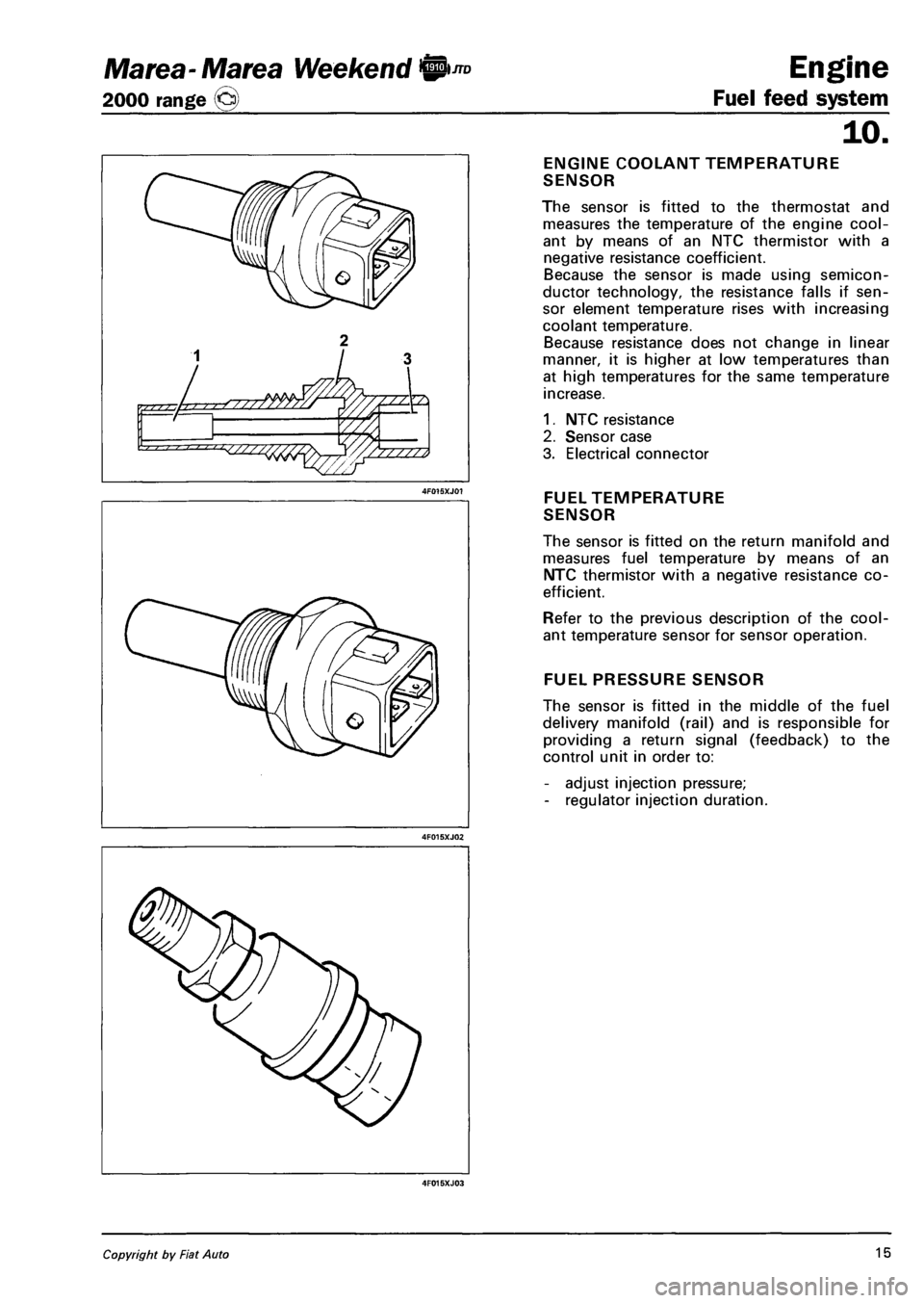
ENGINE COOLANT TEMPERATURE
SENSOR
The sensor is fitted to the thermostat and
measures the temperature of the engine cool
ant by means of an NTC thermistor with a
negative resistance coefficient.
Because the sensor is made using semicon
ductor technology, the resistance falls if sen
sor element temperature rises with increasing
coolant temperature.
Because resistance does not change in linear
manner, it is higher at low temperatures than
at high temperatures for the same temperature
increase.
1. NTC resistance
2. Sensor case
3. Electrical connector
FUEL TEMPERATURE
SENSOR
The sensor is fitted on the return manifold and
measures fuel temperature by means of an
NTC thermistor with a negative resistance co
efficient.
Refer to the previous description of the cool
ant temperature sensor for sensor operation.
FUEL PRESSURE SENSOR
The sensor is fitted in the middle of the fuel
delivery manifold (rail) and is responsible for
providing a return signal (feedback) to the
control unit in order to:
- adjust injection pressure;
- regulator injection duration.
Copyright by Fiat Auto 15
Page 103 of 330
Marea-Marea Weekend 9 -™ Engine
2000 range (j§) Fuel feed system
10.
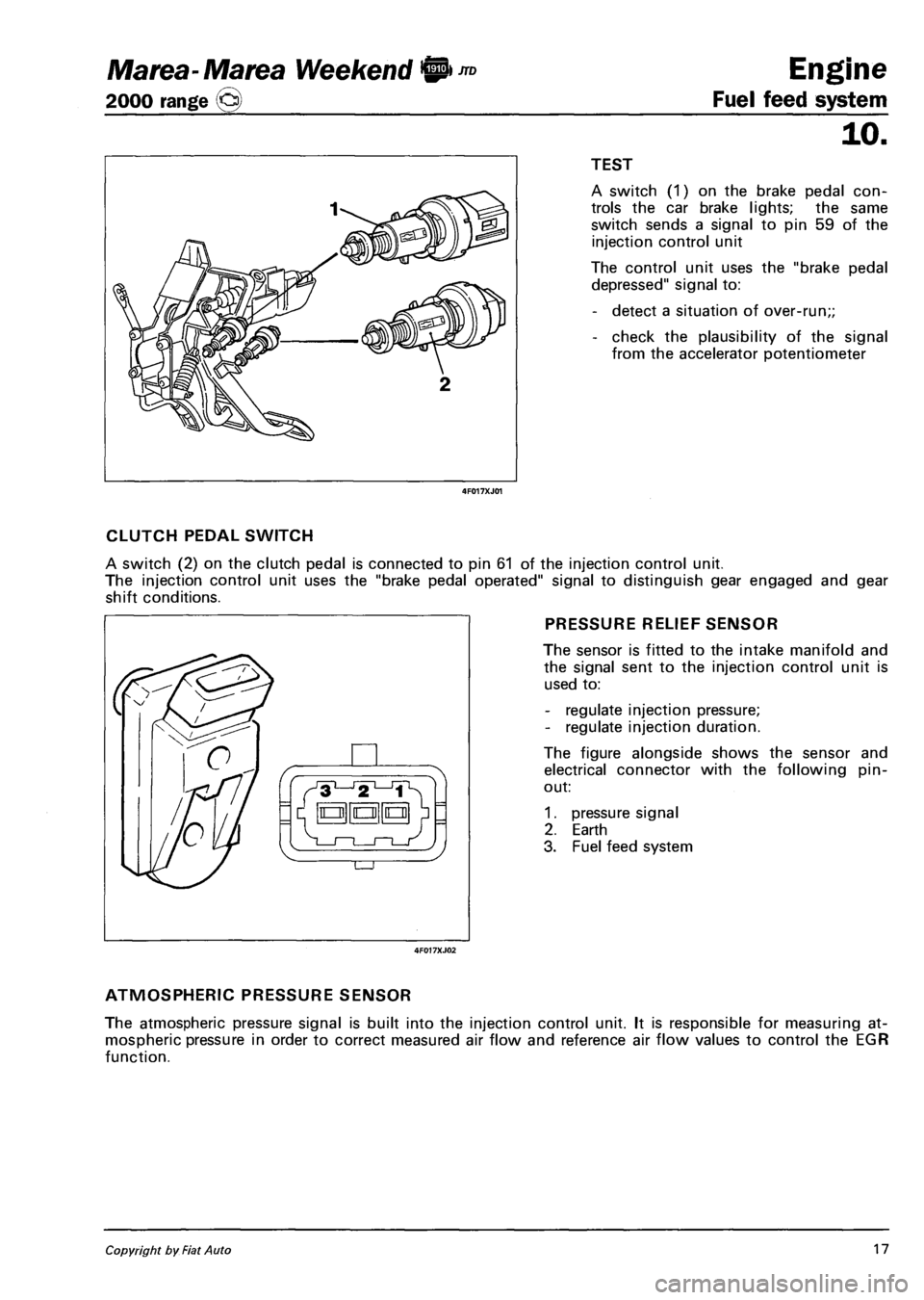
I I TEST
4F017XJ01
A switch (1) on the brake pedal con
trols the car brake lights; the same
switch sends a signal to pin 59 of the
injection control unit
The control unit uses the "brake pedal
depressed" signal to:
- detect a situation of over-run;;
- check the plausibility of the signal
from the accelerator potentiometer
CLUTCH PEDAL SWITCH
A switch (2) on the clutch pedal is connected to pin 61 of the injection control unit.
The injection control unit uses the "brake pedal operated" signal to distinguish gear engaged and gear
shift conditions.
PRESSURE RELIEF SENSOR
The sensor is fitted to the intake manifold and
the signal sent to the injection control unit is
used to:
- regulate injection pressure;
- regulate injection duration.
The figure alongside shows the sensor and
electrical connector with the following pin-
out:
1. pressure signal
2. Earth
3. Fuel feed system
ATMOSPHERIC PRESSURE SENSOR
The atmospheric pressure signal is built into the injection control unit. It is responsible for measuring at
mospheric pressure in order to correct measured air flow and reference air flow values to control the EGR
function.
Copyright by Fiat Auto 17
Page 107 of 330
Marea- Marea Weekend <§l ™
2000 range ©
Engine
Fuel feed system
TZZZZZZZZZZZZZZZZZZb
TZZZZZZZZZZZZZZ*
10.
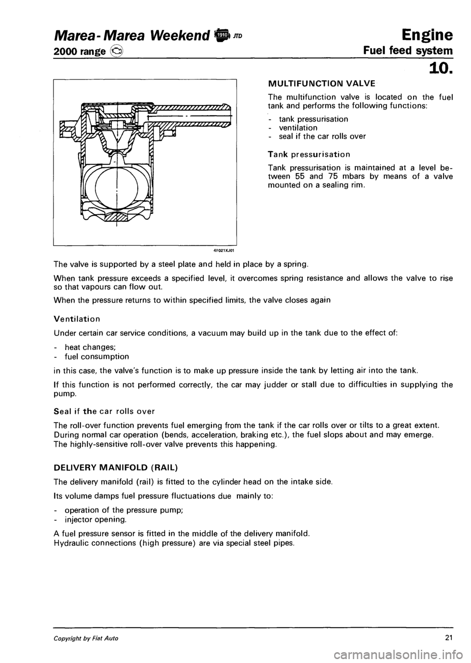
MULTIFUNCTION VALVE
The multifunction valve is located on the fuel
tank and performs the following functions:
- tank pressurisation
- ventilation
- seal if the car rolls over
Tank pressurisation
Tank pressurisation is maintained at a level be
tween 55 and 75 mbars by means of a valve
mounted on a sealing rim.
The valve is supported by a steel plate and held in place by a spring.
When tank pressure exceeds a specified level, it overcomes spring resistance and allows the valve to rise
so that vapours can flow out.
When the pressure returns to within specified limits, the valve closes again
Ventilation
Under certain car service conditions, a vacuum may build up in the tank due to the effect of:
- heat changes;
- fuel consumption
in this case, the valve's function is to make up pressure inside the tank by letting air into the tank.
If this function is not performed correctly, the car may judder or stall due to difficulties in supplying the
pump.
Seal if the car rolls over
The roll-over function prevents fuel emerging from the tank if the car rolls over or tilts to a great extent.
During normal car operation (bends, acceleration, braking etc.), the fuel slops about and may emerge.
The highly-sensitive roll-over valve prevents this happening.
DELIVERY MANIFOLD (RAIL)
The delivery manifold (rail) is fitted to the cylinder head on the intake side.
Its volume damps fuel pressure fluctuations due mainly to:
- operation of the pressure pump;
- injector opening.
A fuel pressure sensor is fitted in the middle of the delivery manifold.
Hydraulic connections (high pressure) are via special steel pipes.
Copyright by Fiat Auto 21
Page 110 of 330
Engine Marea- Marea Weekend 9*nD
Fuel feed system 2000 range (§)
10.
THROTTLE BODY
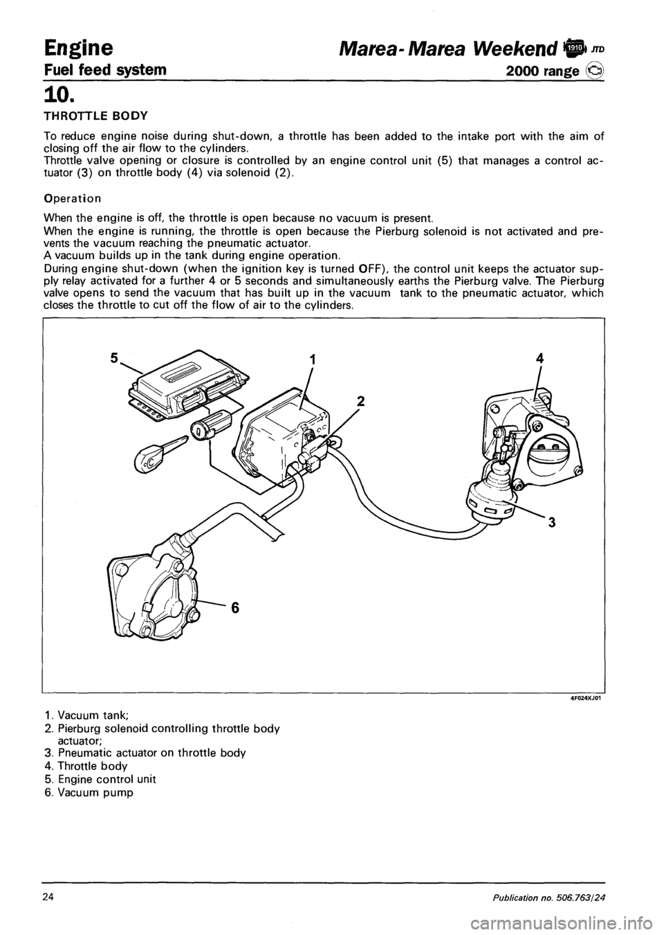
To reduce engine noise during shut-down, a throttle has been added to the intake port with the aim of
closing off the air flow to the cylinders.
Throttle valve opening or closure is controlled by an engine control unit (5) that manages a control ac
tuator (3) on throttle body (4) via solenoid (2).
Operation
When the engine is off, the throttle is open because no vacuum is present.
When the engine is running, the throttle is open because the Pierburg solenoid is not activated and pre
vents the vacuum reaching the pneumatic actuator.
A vacuum builds up in the tank during engine operation.
During engine shut-down (when the ignition key is turned OFF), the control unit keeps the actuator sup
ply relay activated for a further 4 or 5 seconds and simultaneously earths the Pierburg valve. The Pierburg
valve opens to send the vacuum that has built up in the vacuum tank to the pneumatic actuator, which
closes the throttle to cut off the flow of air to the cylinders.
4F024XJ01
1. Vacuum tank;
2. Pierburg solenoid controlling throttle body
actuator;
3. Pneumatic actuator on throttle body
4. Throttle body
5. Engine control unit
6. Vacuum pump
24 Publication no. 506.763/24
Page 111 of 330
Marea- Marea Weekend 9
2000 range ©
Engine
Fuel feed system
10.
TURBOCHARGER (1910 JTD 110 CV)
The turbocharger used in the application of the
EURO 3 standards in the variable geometry
type connected to the exhaust manifold.
The turbocharger is controlled by the engine
management control unit via a duty-cycle so
lenoid valve.
The increased volumetric output for the engine
is achieved, in the case of variable geometry
compressors, through the use of:
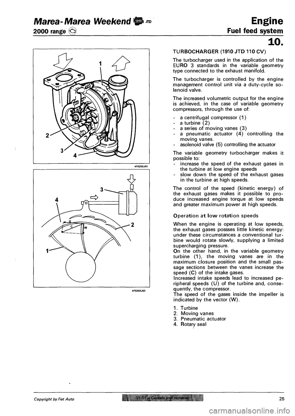
- a centrifugal compressor (1)
- a turbine (2)
- a series of moving vanes (3)
- a pneumatic actuator (4) controlling the
moving vanes.
- asolenoid valve (5) controlling the actuator
The variable geometry turbocharger makes it
possible to:
- increase the speed of the exhaust gases in
the turbine at low engine speeds
- slow down the speed of the exhaust gases
in the turbine at high speeds.
The control of the speed (kinetic energy) of
the exhaust gases makes it possible to pro
duce increased engine torque at low speeds
and greater maximum power at high speeds.
Operation at low rotation speeds
When the engine is operating at low speeds,
the exhaust gases possses little kinetic energy:
under these circumstances a conventional tur
bine would rotate slowly, supplying a limited
supercharging pressure.
On the other hand, in the variable geometry
turbine (1), the moving vanes are in the
maximum closure position and the small pas
sage sections between the vanes increase the
speed (C) of the intake gases.
Increased intake speeds lead to increased pe
ripheral speeds (U) of the turbine and, conse
quently, the compressor.
The speed of the gases inside the impeller is
indicated by the vector (W).
1. Turbine
2. Moving vanes
3. Pneumatic actuator
4. Rotary seal
Copyright by Fiat Auto r VI-01-Cancels arwl replaces.25
Page 112 of 330
Engine
Fuel feed system
JTD Marea- Marea Weekend 9
2000 range @
10.
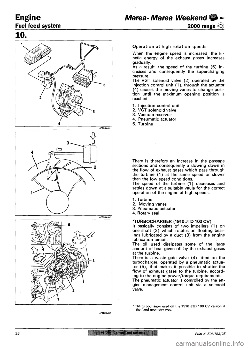
Operation at high rotation speeds
When the engine speed is increased, the ki
netic energy of the exhaust gases increases
gradually.
As a result, the speed of the turbine (5) in
creases and consequently the supercharging
pressure.
The VGT solenoid valve (2) operated by the
injection control unit (1), through the actuator
(4) causes the moving vanes to change posi
tion until the maximum opening position is
reached.
1. Injection control unit
2. VGT solenoid valve
3. Vacuum reservoir
4. Pneumatic actuator
5. Turbine
There is therefore an increase in the passage
sections and consequently a slowing down in
the flow of exhaust gases which pass through
the turbine (1) at the same speed or slower
than the low speed conditions.
The speed of the turbine (1) decreases and
settles down at a suitable vaule for the correct
operation of the engine at high speeds.
1. Turbine
2. Moving vanes
3. Pneumatic actuator
4. Rotary seal
TURBOCHARGER (1910 JTD 100 CV)
It basically consists of two impellers (1) on
one shaft (2) which rotates on floating bear
ings lubricated by a duct (3) from the engine
lubrication circuit.
The oil used dissipates some of the large
amount of heat given off by the exhaust gases
at the turbine.
There is a waste gate valve (4) fitted on the
turbocharger, operated by a pneumatic actua
tor (5), that makes it possible to shutter the
flow of exhaust gases to the turbine, accord
ing to the engine power/torque requirements.
The pneumatic actuator is controlled by the en
gine management control unit via a solenoid
valve.
* The turbocharger used on the 1910 JTD 100 CV version is the fixed geometry type.
26 VI 0^ Cam.frtfi and ri!plact<& Print n° 506.763/25
Page 113 of 330
Marea- Marea Weekend 0 *° Engine
2000 range @ Fuel feed system
10.
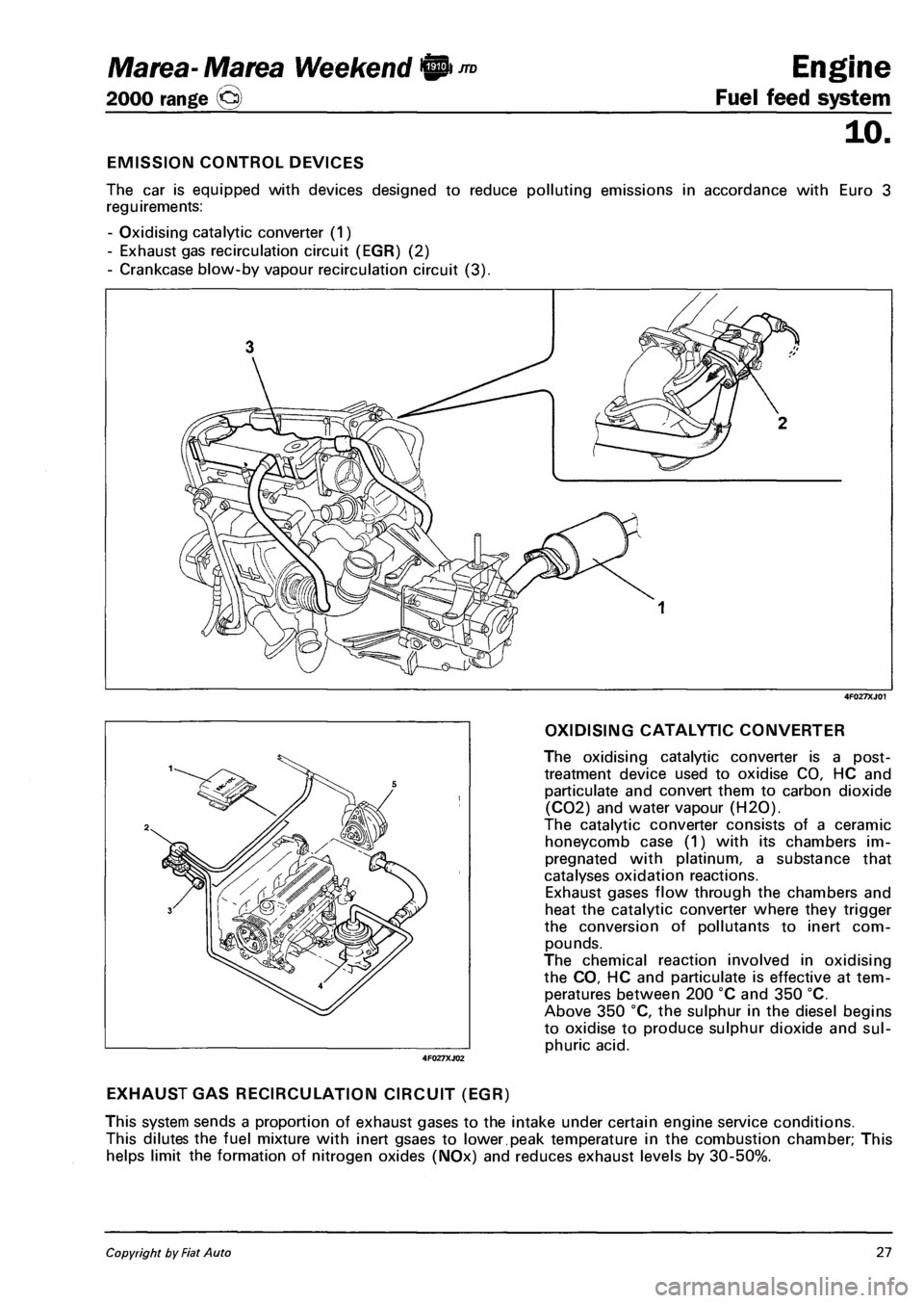
EMISSION CONTROL DEVICES
The car is equipped with devices designed to reduce polluting emissions in accordance with Euro 3
reguirements:
- Oxidising catalytic converter (1)
- Exhaust gas recirculation circuit (EGR) (2)
- Crankcase blow-by vapour recirculation circuit (3).
4F027XJ01
OXIDISING CATALYTIC CONVERTER
The oxidising catalytic converter is a post-
treatment device used to oxidise CO, HC and
particulate and convert them to carbon dioxide
(C02) and water vapour (H20).
The catalytic converter consists of a ceramic
honeycomb case (1) with its chambers im
pregnated with platinum, a substance that
catalyses oxidation reactions.
Exhaust gases flow through the chambers and
heat the catalytic converter where they trigger
the conversion of pollutants to inert com
pounds.
The chemical reaction involved in oxidising
the CO, HC and particulate is effective at tem
peratures between 200 °C and 350 °C.
Above 350 °C, the sulphur in the diesel begins
to oxidise to produce sulphur dioxide and sul
phuric acid.
EXHAUST GAS RECIRCULATION CIRCUIT (EGR)
This system sends a proportion of exhaust gases to the intake under certain engine service conditions.
This dilutes the fuel mixture with inert gsaes to lower.peak temperature in the combustion chamber; This
helps limit the formation of nitrogen oxides (NOx) and reduces exhaust levels by 30-50%.
4F027XJ02
Copyright by Fiat Auto 27