Heat FIAT MAREA 2000 1.G Owner's Manual
[x] Cancel search | Manufacturer: FIAT, Model Year: 2000, Model line: MAREA, Model: FIAT MAREA 2000 1.GPages: 330
Page 105 of 330
Marea- Marea Weekend 9 ™
2000 range (Q)
4F019XJ01
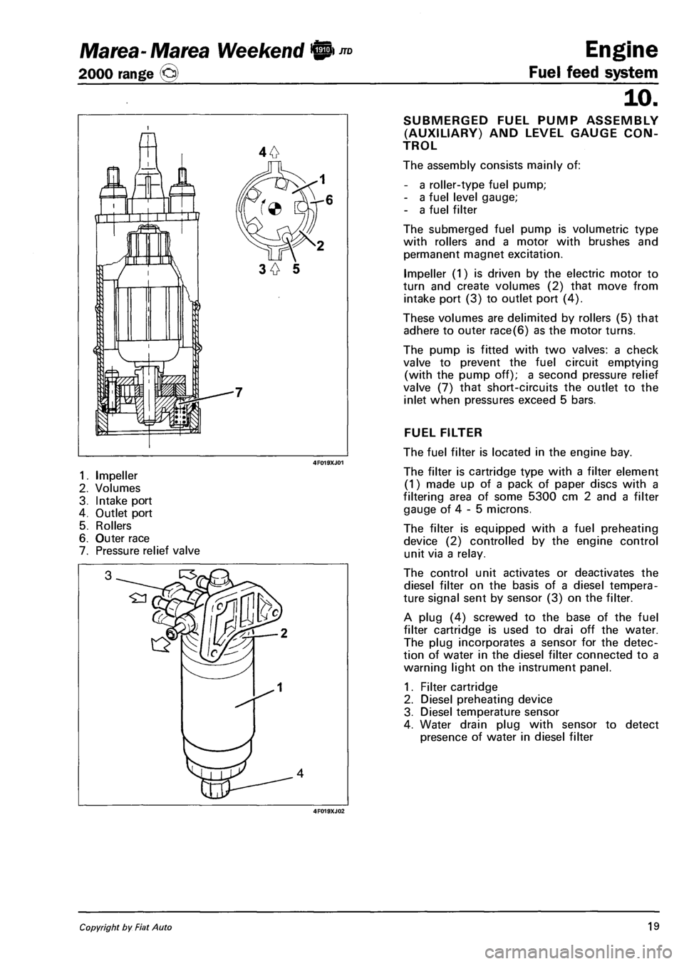
1. Impeller
2. Volumes
3. Intake port
4. Outlet port
5. Rollers
6. Outer race
7. Pressure relief valve
4F019XJ02
Engine
Fuel feed system
10.
SUBMERGED FUEL PUMP ASSEMBLY
(AUXILIARY) AND LEVEL GAUGE CON
TROL
The assembly consists mainly of:
- a roller-type fuel pump;
- a fuel level gauge;
- a fuel filter
The submerged fuel pump is volumetric type
with rollers and a motor with brushes and
permanent magnet excitation.
Impeller (1) is driven by the electric motor to
turn and create volumes (2) that move from
intake port (3) to outlet port (4).
These volumes are delimited by rollers (5) that
adhere to outer race(6) as the motor turns.
The pump is fitted with two valves: a check
valve to prevent the fuel circuit emptying
(with the pump off); a second pressure relief
valve (7) that short-circuits the outlet to the
inlet when pressures exceed 5 bars.
FUEL FILTER
The fuel filter is located in the engine bay.
The filter is cartridge type with a filter element
(1) made up of a pack of paper discs with a
filtering area of some 5300 cm 2 and a filter
gauge of 4 - 5 microns.
The filter is equipped with a fuel preheating
device (2) controlled by the engine control
unit via a relay.
The control unit activates or deactivates the
diesel filter on the basis of a diesel tempera
ture signal sent by sensor (3) on the filter.
A plug (4) screwed to the base of the fuel
filter cartridge is used to drai off the water.
The plug incorporates a sensor for the detec
tion of water in the diesel filter connected to a
warning light on the instrument panel.
1. Filter cartridge
2. Diesel preheating device
3. Diesel temperature sensor
4. Water drain plug with sensor to detect
presence of water in diesel filter
Copyright by Fiat Auto 19
Page 107 of 330
Marea- Marea Weekend <§l ™
2000 range ©
Engine
Fuel feed system
TZZZZZZZZZZZZZZZZZZb
TZZZZZZZZZZZZZZ*
10.
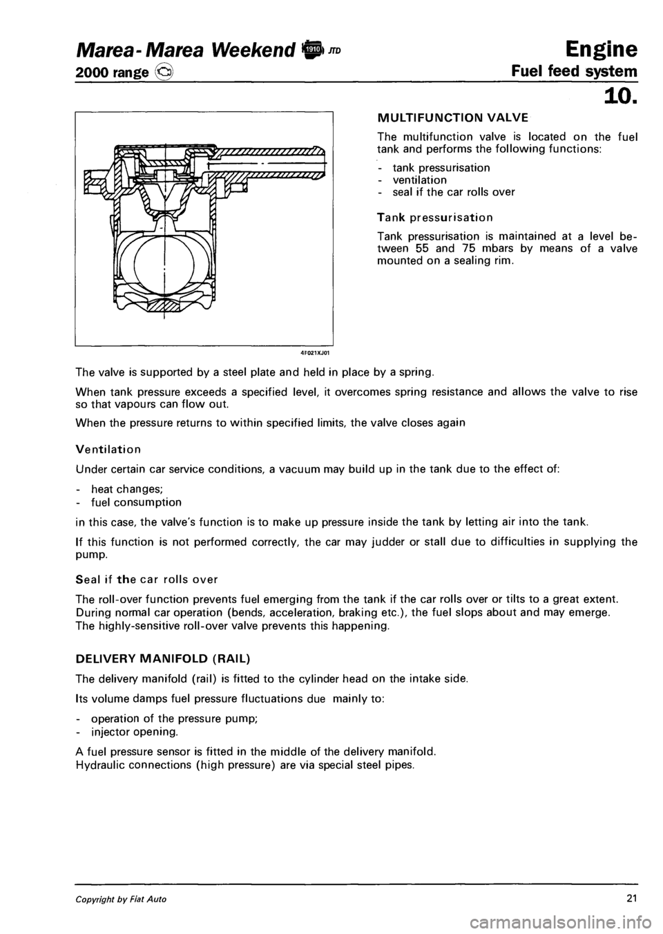
MULTIFUNCTION VALVE
The multifunction valve is located on the fuel
tank and performs the following functions:
- tank pressurisation
- ventilation
- seal if the car rolls over
Tank pressurisation
Tank pressurisation is maintained at a level be
tween 55 and 75 mbars by means of a valve
mounted on a sealing rim.
The valve is supported by a steel plate and held in place by a spring.
When tank pressure exceeds a specified level, it overcomes spring resistance and allows the valve to rise
so that vapours can flow out.
When the pressure returns to within specified limits, the valve closes again
Ventilation
Under certain car service conditions, a vacuum may build up in the tank due to the effect of:
- heat changes;
- fuel consumption
in this case, the valve's function is to make up pressure inside the tank by letting air into the tank.
If this function is not performed correctly, the car may judder or stall due to difficulties in supplying the
pump.
Seal if the car rolls over
The roll-over function prevents fuel emerging from the tank if the car rolls over or tilts to a great extent.
During normal car operation (bends, acceleration, braking etc.), the fuel slops about and may emerge.
The highly-sensitive roll-over valve prevents this happening.
DELIVERY MANIFOLD (RAIL)
The delivery manifold (rail) is fitted to the cylinder head on the intake side.
Its volume damps fuel pressure fluctuations due mainly to:
- operation of the pressure pump;
- injector opening.
A fuel pressure sensor is fitted in the middle of the delivery manifold.
Hydraulic connections (high pressure) are via special steel pipes.
Copyright by Fiat Auto 21
Page 108 of 330
Engine
Fuel feed system
Marea- Marea Weekend W)JTD
2000 range ©
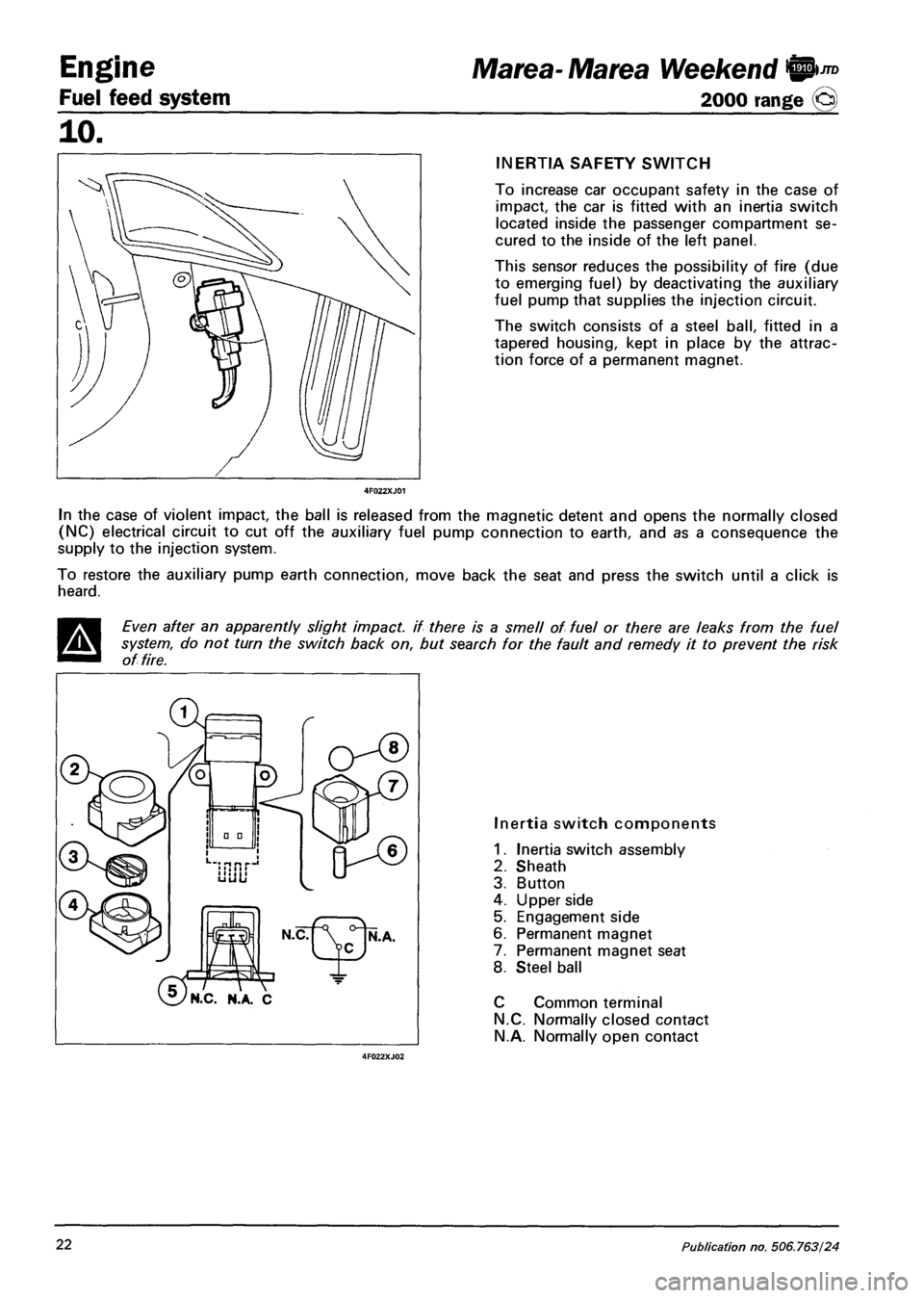
INERTIA SAFETY SWITCH
To increase car occupant safety in the case of
impact, the car is fitted with an inertia switch
located inside the passenger compartment se
cured to the inside of the left panel.
This sensor reduces the possibility of fire (due
to emerging fuel) by deactivating the auxiliary
fuel pump that supplies the injection circuit.
The switch consists of a steel ball, fitted in a
tapered housing, kept in place by the attrac
tion force of a permanent magnet.
In the case of violent impact, the ball is released from the magnetic detent and opens the normally closed
(NC) electrical circuit to cut off the auxiliary fuel pump connection to earth, and as a consequence the
supply to the injection system.
To restore the auxiliary pump earth connection, move back the seat and press the switch until a click is
heard.
Even after an apparently slight impact, if there is a smell of fuel or there are leaks from the fuel
system, do not turn the switch back on, but search for the fault and remedy it to prevent the risk
of fire.
'N.C. N.A. C
Inertia switch components
1. Inertia switch assembly
2. Sheath
3. Button
4. Upper side
5. Engagement side
6. Permanent magnet
7. Permanent magnet seat
8. Steel ball
C Common terminal
N.C. Normally closed contact
N.A. Normally open contact
22 Publication no. 506.763/24
Page 112 of 330
Engine
Fuel feed system
JTD Marea- Marea Weekend 9
2000 range @
10.
Operation at high rotation speeds
When the engine speed is increased, the ki
netic energy of the exhaust gases increases
gradually.
As a result, the speed of the turbine (5) in
creases and consequently the supercharging
pressure.
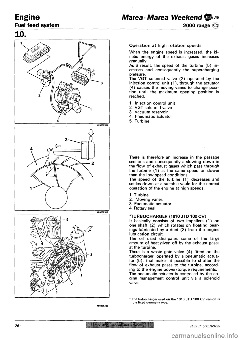
The VGT solenoid valve (2) operated by the
injection control unit (1), through the actuator
(4) causes the moving vanes to change posi
tion until the maximum opening position is
reached.
1. Injection control unit
2. VGT solenoid valve
3. Vacuum reservoir
4. Pneumatic actuator
5. Turbine
There is therefore an increase in the passage
sections and consequently a slowing down in
the flow of exhaust gases which pass through
the turbine (1) at the same speed or slower
than the low speed conditions.
The speed of the turbine (1) decreases and
settles down at a suitable vaule for the correct
operation of the engine at high speeds.
1. Turbine
2. Moving vanes
3. Pneumatic actuator
4. Rotary seal
TURBOCHARGER (1910 JTD 100 CV)
It basically consists of two impellers (1) on
one shaft (2) which rotates on floating bear
ings lubricated by a duct (3) from the engine
lubrication circuit.
The oil used dissipates some of the large
amount of heat given off by the exhaust gases
at the turbine.
There is a waste gate valve (4) fitted on the
turbocharger, operated by a pneumatic actua
tor (5), that makes it possible to shutter the
flow of exhaust gases to the turbine, accord
ing to the engine power/torque requirements.
The pneumatic actuator is controlled by the en
gine management control unit via a solenoid
valve.
* The turbocharger used on the 1910 JTD 100 CV version is the fixed geometry type.
26 VI 0^ Cam.frtfi and ri!plact<& Print n° 506.763/25
Page 113 of 330
Marea- Marea Weekend 0 *° Engine
2000 range @ Fuel feed system
10.
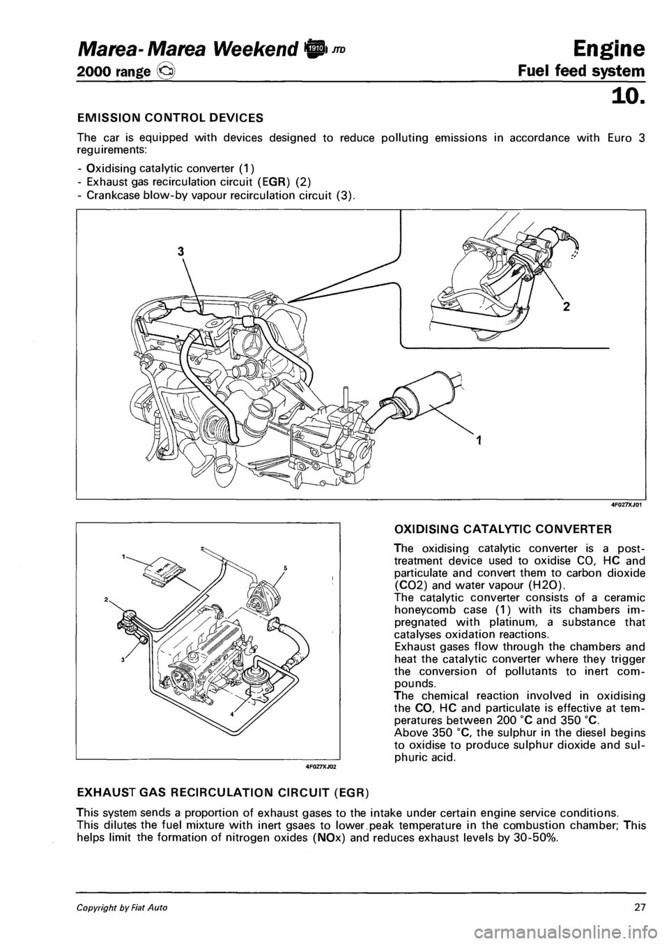
EMISSION CONTROL DEVICES
The car is equipped with devices designed to reduce polluting emissions in accordance with Euro 3
reguirements:
- Oxidising catalytic converter (1)
- Exhaust gas recirculation circuit (EGR) (2)
- Crankcase blow-by vapour recirculation circuit (3).
4F027XJ01
OXIDISING CATALYTIC CONVERTER
The oxidising catalytic converter is a post-
treatment device used to oxidise CO, HC and
particulate and convert them to carbon dioxide
(C02) and water vapour (H20).
The catalytic converter consists of a ceramic
honeycomb case (1) with its chambers im
pregnated with platinum, a substance that
catalyses oxidation reactions.
Exhaust gases flow through the chambers and
heat the catalytic converter where they trigger
the conversion of pollutants to inert com
pounds.
The chemical reaction involved in oxidising
the CO, HC and particulate is effective at tem
peratures between 200 °C and 350 °C.
Above 350 °C, the sulphur in the diesel begins
to oxidise to produce sulphur dioxide and sul
phuric acid.
EXHAUST GAS RECIRCULATION CIRCUIT (EGR)
This system sends a proportion of exhaust gases to the intake under certain engine service conditions.
This dilutes the fuel mixture with inert gsaes to lower.peak temperature in the combustion chamber; This
helps limit the formation of nitrogen oxides (NOx) and reduces exhaust levels by 30-50%.
4F027XJ02
Copyright by Fiat Auto 27
Page 114 of 330
Engine Marea- Marea Weekend IP ™
Fuel feed system 2000 range o
10.
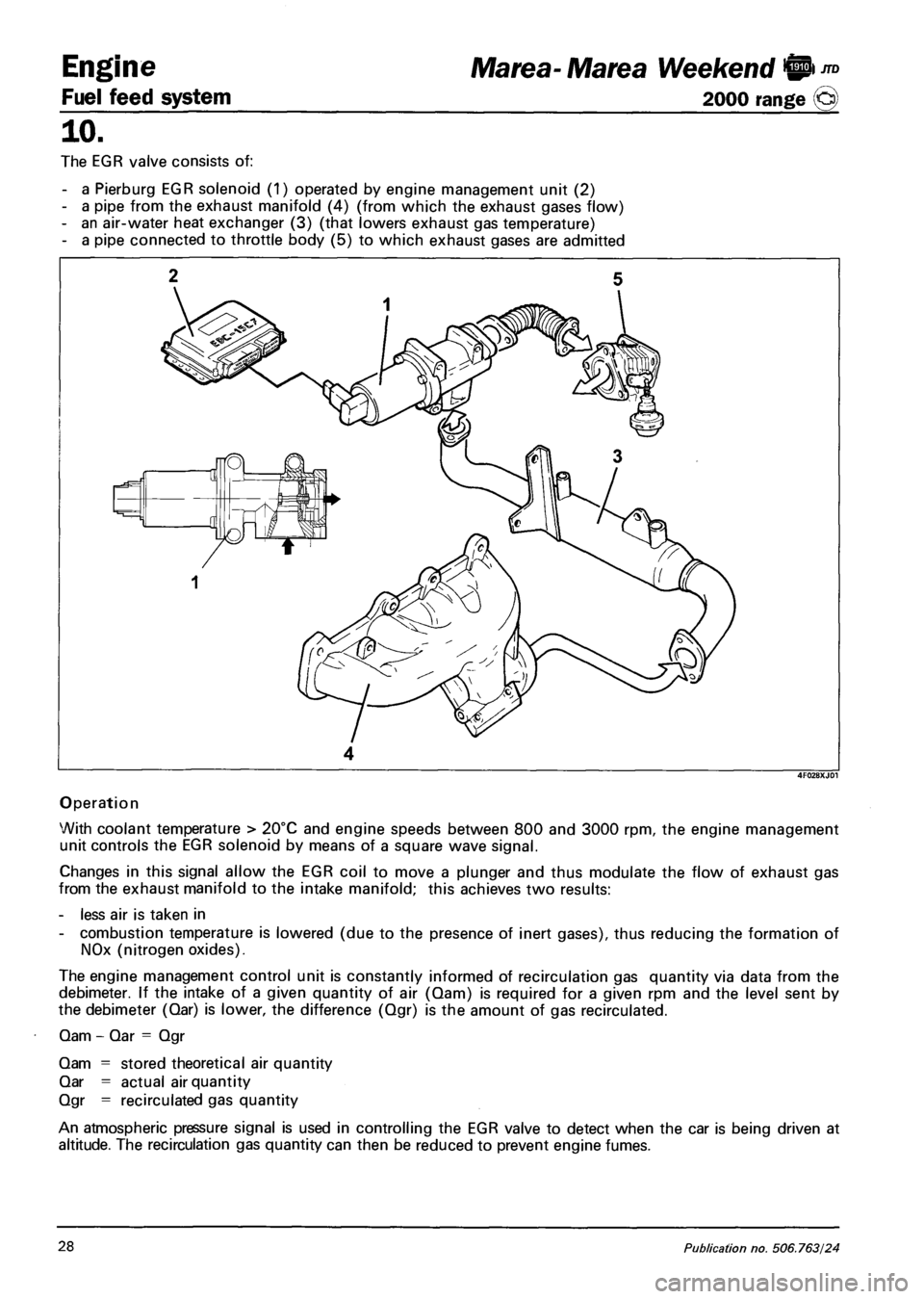
The EGR valve consists of:
- a Pierburg EGR solenoid (1) operated by engine management unit (2)
- a pipe from the exhaust manifold (4) (from which the exhaust gases flow)
- an air-water heat exchanger (3) (that lowers exhaust gas temperature)
- a pipe connected to throttle body (5) to which exhaust gases are admitted
4
Operation
With coolant temperature > 20°C and engine speeds between 800 and 3000 rpm, the engine management
unit controls the EGR solenoid by means of a square wave signal.
Changes in this signal allow the EGR coil to move a plunger and thus modulate the flow of exhaust gas
from the exhaust manifold to the intake manifold; this achieves two results:
- less air is taken in
- combustion temperature is lowered (due to the presence of inert gases), thus reducing the formation of
NOx (nitrogen oxides).
The engine management control unit is constantly informed of recirculation gas quantity via data from the
debimeter. If the intake of a given quantity of air (Qam) is required for a given rpm and the level sent by
the debimeter (Qar) is lower, the difference (Qgr) is the amount of gas recirculated.
Qam - Qar = Qgr
Qam = stored theoretical air quantity
Qar = actual air quantity
Qgr = recirculated gas quantity
An atmospheric pressure signal is used in controlling the EGR valve to detect when the car is being driven at
altitude. The recirculation gas quantity can then be reduced to prevent engine fumes.
28 Publication no. 506.763/24
Page 117 of 330
Marea- Marea Weekend 9 *°
2000 range @)
Engine
Fuel feed system
10.
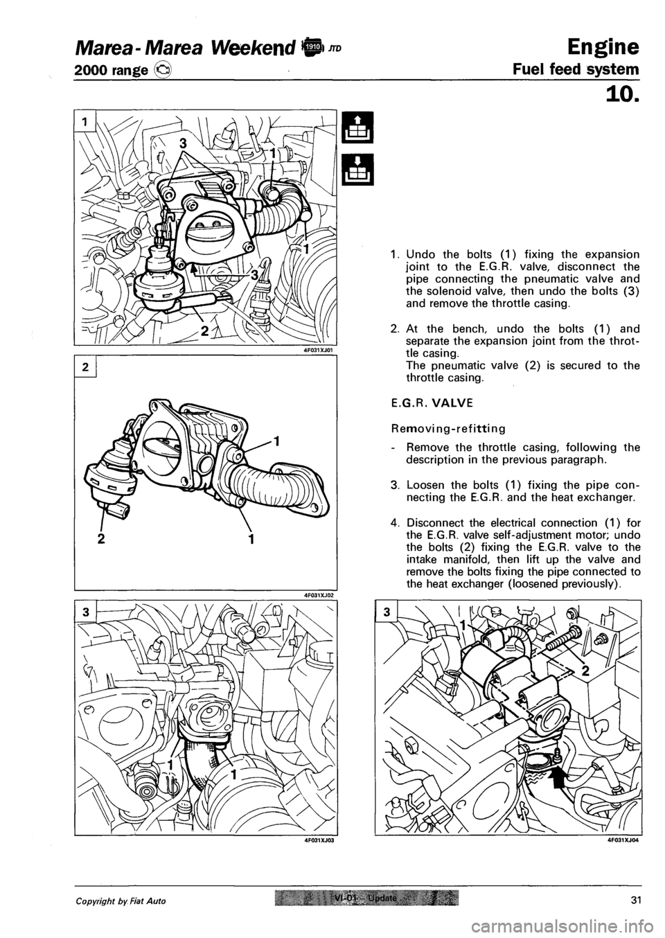
1. Undo the bolts (1) fixing the expansion
joint to the E.G.R. valve, disconnect the
pipe connecting the pneumatic valve and
the solenoid valve, then undo the bolts (3)
and remove the throttle casing.
2. At the bench, undo the bolts (1) and
separate the expansion joint from the throt
tle casing.
The pneumatic valve (2) is secured to the
throttle casing.
E.G.R. VALVE
Removing-refitting
- Remove the throttle casing, following the
description in the previous paragraph.
3. Loosen the bolts (1) fixing the pipe con
necting the E.G.R. and the heat exchanger.
4. Disconnect the electrical connection (1) for
the E.G.R. valve self-adjustment motor; undo
the bolts (2) fixing the E.G.R. valve to the
intake manifold, then lift up the valve and
remove the bolts fixing the pipe connected to
the heat exchanger (loosened previously).
Copyright by Fiat Auto VI 01 i ndate 31
Page 118 of 330
Engine
Fuel feed system
JTD Marea-Marea Weekend 9
2000 range ©
E.G.R.
TOR
VALVE SELF-ADJUSTMENT MO-
Removing-refitting
- Disconnect the negative battery lead, then
remove the sound insulation shield follow
ing the instructions in the previous para
graphs.
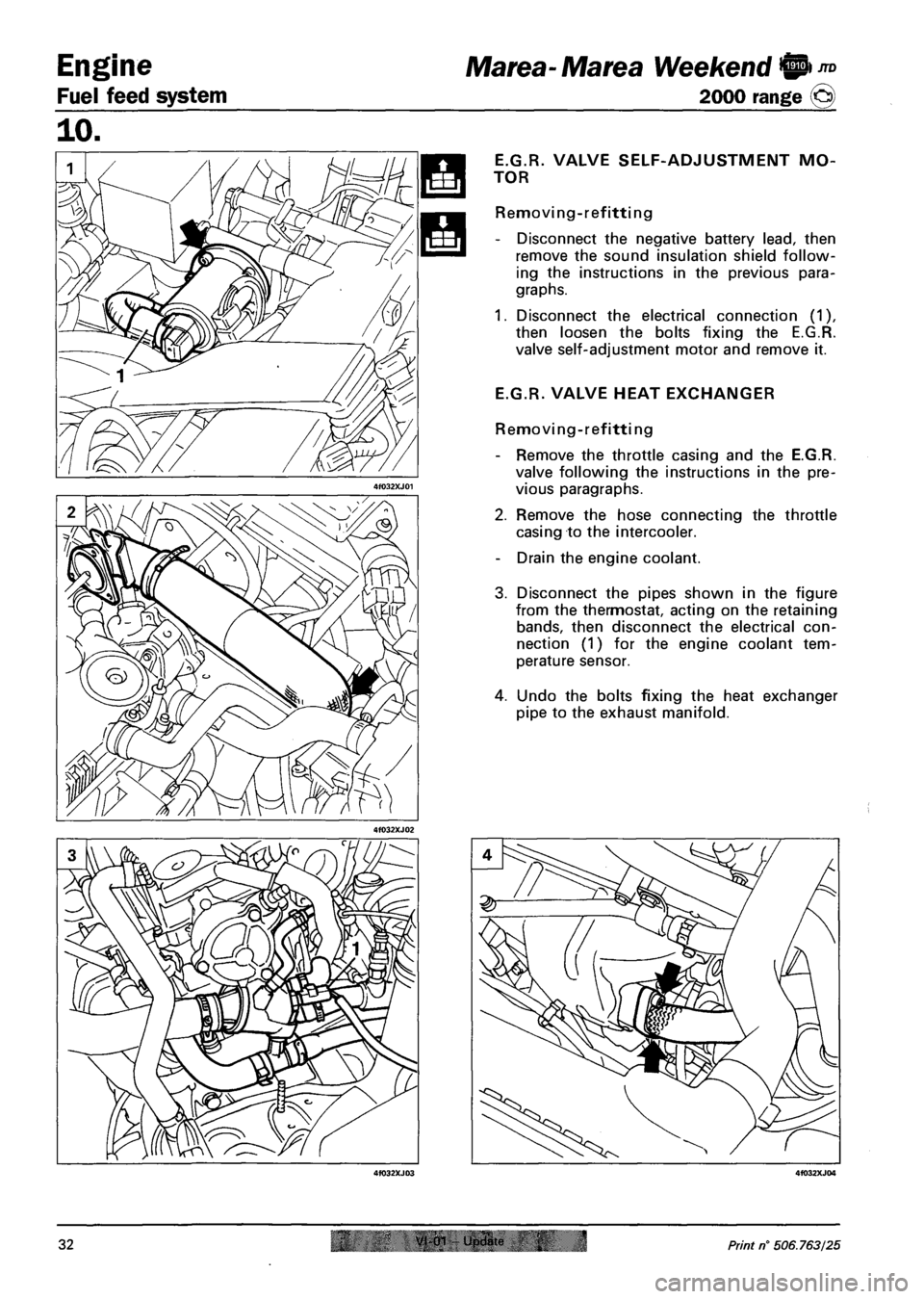
1. Disconnect the electrical connection (1),
then loosen the bolts fixing the E.G.R.
valve self-adjustment motor and remove it.
E.G.R. VALVE HEAT EXCHANGER
Removi ng - ref itti ng
- Remove the throttle casing and the E.G.R.
valve following the instructions in the pre
vious paragraphs.
2. Remove the hose connecting the throttle
casing to the intercooler.
- Drain the engine coolant.
3. Disconnect the pipes shown in the figure
from the thermostat, acting on the retaining
bands, then disconnect the electrical con
nection (1) for the engine coolant tem
perature sensor.
4. Undo the bolts fixing the heat exchanger
pipe to the exhaust manifold.
32 0"" Und«r 4 Print n° 506.763/25
Page 119 of 330
Marea- Marea Weekend 9
2000 range ©
Engine
Fuel feed system
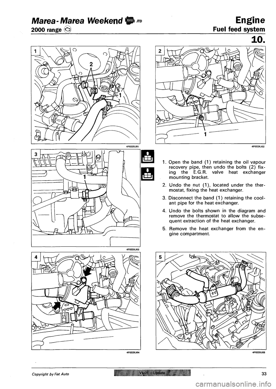
Open the band (1) retaining the oil vapour
recovery pipe, then undo the bolts (2) fix
ing the E.G.R. valve heat exchanger
mounting bracket.
Undo the nut (1), located under the ther
mostat, fixing the heat exchanger.
Disconnect the band (1) retaining the cool
ant pipe for the heat exchanger.
Undo the bolts shown in the diagram and
remove the thermostat to allow the subse
quent extraction of the heat exchanger.
Remove the heat exchanger from the en
gine compartment.
Copyright by Fiat Auto VK01 - Update ,f 33
Page 131 of 330
Marea- Marea Weekend
2000 range ©
Electrical equipment
Protection and security devices
55.
PROTECTION AND SAFETY DEVICES
All the vehicle supply lines were designed taking into account the most up-to-date directives in terms of
safety and protection, especially to prevent fires.
There are 2 types of protection:
- active protection, aims to reduce the causes of faults "at source"
- passive protection, aims to limit the effects of a fault as much as possible
The first category includes a carefully designed wiring layout with wires positioned and carefully anchored
on tracks that are repaired and protected if necessary.
The cables connected to the alternator and the motor were modified for this reason by adding protective
caps etc. A strengthened sheath was also introduced for some of the more exposed sections of wiring.
The passive protection includes all interventions to reduce faults due to high current (overload, short cir
cuit).
All system fuses were rated based on the nominal absorbtion of the loads activated at the same time, to
ensure intervention in cases of a clear short circuit.
The introduction of a box containing 4 maxifuses with other fuses connected on the outside means all
the supplies can be protected except for the cable that connects the battery to the starter motor and the
cable that connects the starter motor to the recharging alternator. These cables are therefore protected by a
strengthened supplementary sheath.
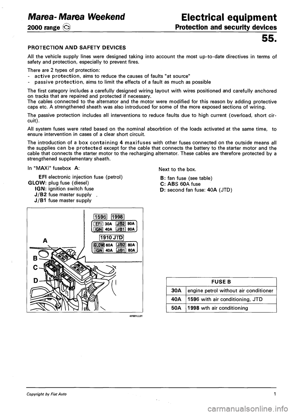
In "MAXI" fusebox A:
EFI electronic injection fuse (petrol)
GLOW: plug fuse (diesel)
IGN: ignition switch fuse
J/B2 fuse master supply .
J/B1 fuse master supply
Next to the box.
B: fan fuse (see table)
C: ABS 60A fuse
D: second fan fuse: 40A (JTD)
115961 1998
iFil 30A IJ/B21 BOA
fiGNl 4OA IJTBTI BOA
1910JTD
IGLOWl 60A P7B21 80A
MGNI 40A IJ/Bll 80A
FUSE B
30A engine petrol without air conditioner
40A 1596 with air conditioning, JTD
50A 1998 wth air conditioning
Copyright by Fiat Auto 1