diagram FIAT MAREA 2000 1.G Owner's Manual
[x] Cancel search | Manufacturer: FIAT, Model Year: 2000, Model line: MAREA, Model: FIAT MAREA 2000 1.GPages: 330
Page 126 of 330
Marea- Marea Weekend
2000 range ©
Auxiliary Units
Climate control
50
COMPRESSOR ( 1596 engine)
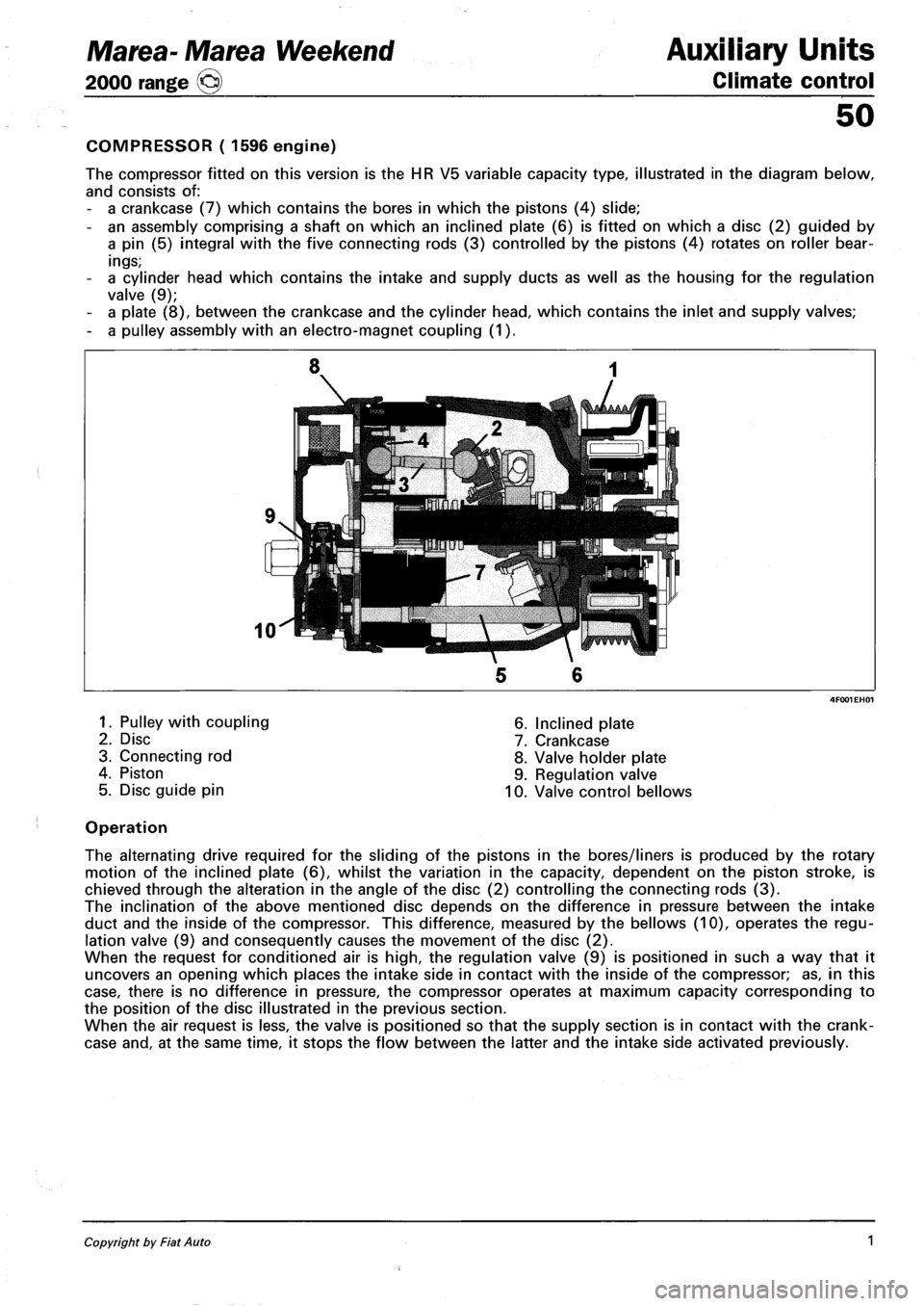
The compressor fitted on this version is the HR V5 variable capacity type, illustrated in the diagram below,
and consists of:
- a crankcase (7) which contains the bores in which the pistons (4) slide;
- an assembly comprising a shaft on which an inclined plate (6) is fitted on which a disc (2) guided by
a pin (5) integral with the five connecting rods (3) controlled by the pistons (4) rotates on roller bear
ings;
- a cylinder head which contains the intake and supply ducts as well as the housing for the regulation
valve (9);
- a plate (8), between the crankcase and the cylinder head, which contains the inlet and supply valves;
- a pulley assembly with an electro-magnet coupling (1).
1. Pulley with coupling
2. Disc
3. Connecting rod
4. Piston
5. Disc guide pin
6. Inclined plate
7. Crankcase
8. Valve holder plate
9. Regulation valve
10. Valve control bellows
Operation
The alternating drive required for the sliding of the pistons in the bores/liners is produced by the rotary
motion of the inclined plate (6), whilst the variation in the capacity, dependent on the piston stroke, is
chieved through the alteration in the angle of the disc (2) controlling the connecting rods (3).
The inclination of the above mentioned disc depends on the difference in pressure between the intake
duct and the inside of the compressor. This difference, measured by the bellows (10), operates the regu
lation valve (9) and consequently causes the movement of the disc (2).
When the request for conditioned air is high, the regulation valve (9) is positioned in such a way that it
uncovers an opening which places the intake side in contact with the inside of the compressor; as, in this
case, there is no difference in pressure, the compressor operates at maximum capacity corresponding to
the position of the disc illustrated in the previous section.
When the air request is less, the valve is positioned so that the supply section is in contact with the crank
case and, at the same time, it stops the flow between the latter and the intake side activated previously.
Copyright by Fiat Auto 1
Page 127 of 330
Auxiliary Units
Climate control
Marea-Marea Weekend
2000 range O
50
COMPRESSOR (1910 JTD)
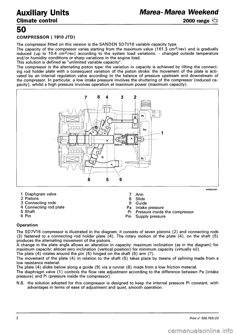
The compressor fitted on this version is the SANDEN SD7V16 variable capacity type.
The capacity of the compressor varies starting from the maximum value (161.3 cm^/rev) and is gradually
reduced (up to 10.4 cm^/rev) according to the system load variations. - changed outside temperature
and/or humidity conditions or sharp variations in the engine load.
This solution is defined as "unlimited variable capacity".
The compressor is the alternating piston type: the variation in capacity is achieved by tilting the connect
ing rod holder plate with a consequent variation of the piston stroke: the movement of the plate is acti
vated by an internal regulation valve according to the balance of pressure upstream and downstream of
the compressor. In particular, a low intake pressure involves the shuttering of the compressor (reduced ca
pacity), whilst a high pressure involves operation at maximum power (maximum capacity).
7 6 4 3 2
5 9
1 Diaphgram valve
2 Pistons
3 Connecting rods
4 Connecting rod plate
5 Shaft
6 Pin
7 Arm
8 Slide
9 Guide
Pa Intake pressure
Pi Pressure inside the compressor
Pm Supply pressure
Operation
The SD7V16 compressor is illustrated in the diagram; it consists of seven pistons (2) and connecting rods
(3) fastened to a connecting rod holder plate (4). The rotary motion of the plate (4), on the shaft (5)
produces the alternating movement of the pistons.
A change in the plate angle allows an alteration in capacity: maximum inclination (as in the diagram) for
maximum capacity; almost zero inclination (vertical position) for minimum capacity (virtually nil).
The plate (4) rotates around the pin (6) hinged on the shaft (5) arm (7).
The movement of the plate (4) in relation to the shaft (5) takes place by means of splining made from a
low resistance material.
The plate (4) slides below along a guide (9) via a runner (8) made from a low friction material.
The diaphragm valve (1) controls the flow rate adjustment according to the difference between Pa (intake
pressure) and Pi (pressure inside the compressor).
N.B. the solution adopted for this compressor is designed to keep the internal pressure Pi constant, with
advantages in terms of ease of adjustment and quiet, smooth operation.
2 Print n° 506.763/23
Page 132 of 330
Electrical equipment
Protection and safety devices
Marea- Marea Weekend
2000 range ©)
55.
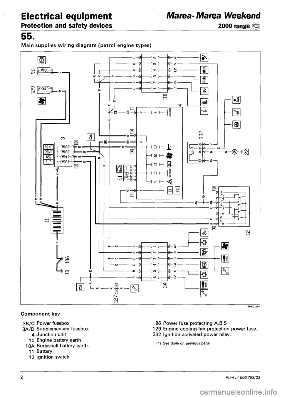
Main supplies wiring diagram (petrol engine types)
Component key
3B/C Power fusebox
3A/D Supplementary fusebox
4 Junction unit
10 Engine battery earth
10A Bodyshell battery earth.
11 Battery
12 Ignition switch
96 Power fuse protecting A.B.S
129 Engine cooling fan protection power fuse.
332 Ignition activated power relay.
(*) See table on previous page.
2 Print n° 506.763/23
Page 133 of 330
Marea- Marea Weekend
2000 range ©)
Electrical equipment
Protection and safety devices
55.
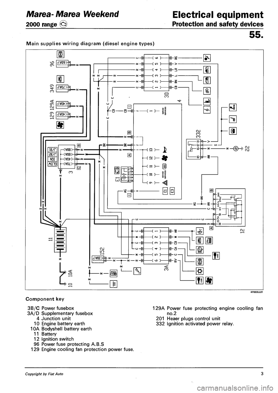
Main supplies wiring diagram (diesel engine types)
Component key
3B/C Power fusebox
3A/D Supplementary fusebox
4 Junction unit
10 Engine battery earth
10A Bodyshell battery earth
11 Battery
12 Ignition switch
96 Power fuse protecting A.B.S
129 Engine cooling fan protection power fuse.
129A Power fuse protecting engine cooling fan
no.2
201 Heaer plugs control unit
332 Ignition activated power relay.
Copyright by Fiat Auto 3
Page 134 of 330
Electrical equipment
Junction unit
Marea-Marea Weekend
2000 range ©
55.
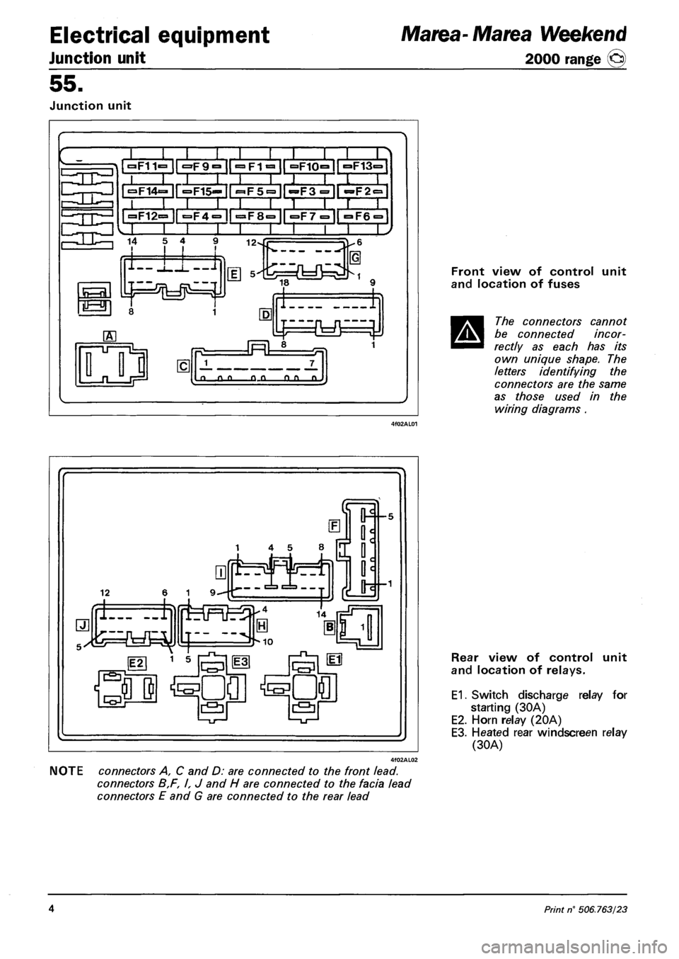
Junction unit
»F11=
~T~ II l;
•F9° |["^FT^1| °F10°ir°F13=
| ^14=- ir=F15«=- II
»F12=
SLHHItHia r i i i •
3F4= ir^F8=1l =F7="|| °F6 = 1
I I I I I 1 I '
14 5 4 12-
lor
1-11-J
I 1
J 7_
a o_o o_o OLD n.
Front view of control unit
and location of fuses
The connectors cannot
be connected incor
rectly as each has its
own unique shape. The
letters identifying the
connectors are the same
as those used in the
wiring diagrams .
NOTE connectors A, C and D: are connected to the front lead.
connectors B,F, I, J and H are connected to the facia lead
connectors E and G are connected to the rear lead
Rear view of control unit
and location of relays.
E1. Switch discharge relay for
starting (30A)
E2. Horn relay (20A)
E3. Heated rear windscreen relay
(30A)
4 Print n° 506.763/23
Page 145 of 330
Marea- Marea Weekend
2000 range ©
Electrical equipment
Control module
55.
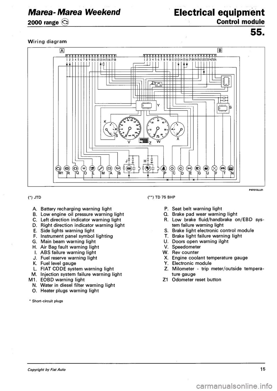
Wiring diagram
.mrmmmL 18 3 4 5 6 7 8 9 10 U 1213 1415161718 |TTTTrTrrrrTTTTT1.TTTTT1pmL 18 3 4 5 6 7 8 9 10 11 121314151617181920213223248586
n ti
O Mill
(*) JTD
A. Battery recharging warning light
B. Low engine oil pressure warning light
C. Left direction indicator warning light
D. Right direction indicator warning light
E. Side lights warning light
F. Instrument panel symbol lighting
G. Main beam warning light
H. Air Bag fault warning light
I. ABS failure warning light
J. Fuel reserve warning light
K. Fuel level gauge
L. FIAT CODE system warning light
M. Injection system failure warning light
M1. EOBD warning light
N. Water in diesel filter warning light
O. Heater plugs warning light
(**) TD 75 BHP
P. Seat belt warning light
Q. Brake pad wear warning light
R. Low brake fluid/handbrake on/EBD sys
tem failure warning light
S. Brake light electronic control module
T. Brake light failure warning light
U. Doors open warning ilght
V. Speedometer
W. Rev counter
X. Engine coolant temperature gauge
Y. Electronic module
Z. Milometer - trip meter/outside tempera
ture gauge
Z1 Odometer reset button
* Short-circuit plugs
Copyright by Fiat Auto 15
Page 183 of 330
Marea-Marea Weekend
2000 range ©
Electrical equipment
Index
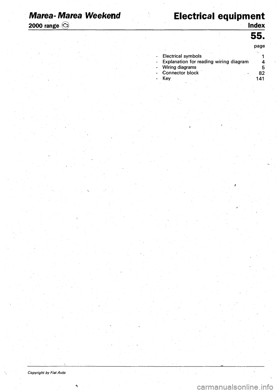
Electrical symbols
Explanation for reading wiring diagram
Wiring diagrams
Connector block
Key
55.
page
1
4
5
82
141
Copyright by Fiat Auto
Page 184 of 330
Marea-Marea Weekend Electrical system
2000 range ©> Wiring diagrams
55.
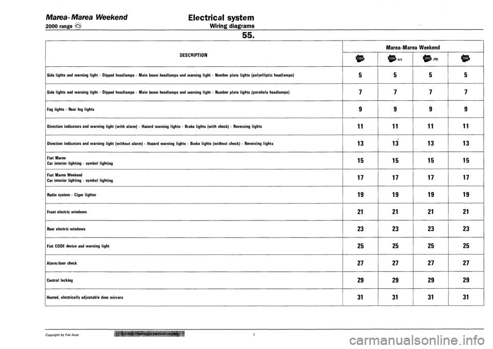
DESCRIPTION
Marea-Marea Weekend
DESCRIPTION JTD
SIDE LIGHTS AND WARNING LIGHT - DIPPED HEADLAMPS - MAIN BEAM HEADLAMPS AND WARNING LIGHT - NUMBER PLATE LIGHTS (POLYELLIPTIC HEADLAMPS) 5 5 5 5
SIDE LIGHTS AND WARNING LIGHT - DIPPED HEADLAMPS - MAIN BEAM HEADLAMPS AND WARNING LIGHT - NUMBER PLATE LIGHTS (PARABOLA HEADLAMPS) 7 7 7 7
FOG LIGHTS - REAR FOG LIGHTS 9 9 9 9
DIRECTION INDICATORS AND WARNING LIGHT (WITH ALARM) - HAZARD WARNING LIGHTS - BRAKE LIGHTS (WITH CHECK) - REVERSING LIGHTS 11 11 11 11
DIRECTION INDICATORS AND WARNING LIGHT (WITHOUT ALARM) - HAZARD WARNING LIGHTS - BRAKE LIGHTS (WITHOUT CHECK) - REVERSING LIGHTS 13 13 13 13
FIAT MAREA
CAR INTERIOR LIGHTING - SYMBOL LIGHTING 15 15 15 15
FIAT MAREA WEEKEND
CAR INTERIOR LIGHTING - SYMBOL LIGHTING 17 17 17 17
RADIO SYSTEM - CIGAR LIGHTER 19 19 19 19
FRONT ELECTRIC WINDOWS 21 21 21 21
REAR ELECTRIC WINDOWS 23 23 23 23
FIAT CODE DEVICE AND WARNING LIGHT 25 25 25 25
ALARM/DOOR CHECK 27 27 27 27
CENTRAL LOCKING 29 29 29 29
HEATED, ELECTRICALLY ADJUSTABLE DOOR MIRRORS 31 31 31 31
Copyright by Fiat Auto '' XI Supersedes previous verster*.
Page 185 of 330
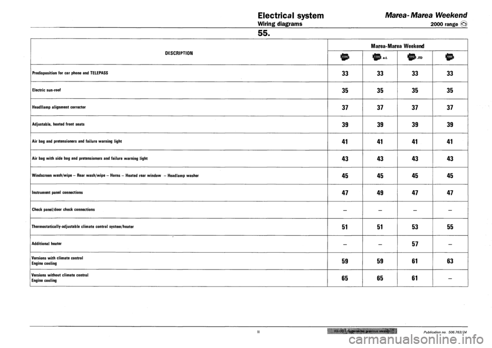
Electrical system Marea-Marea Weekend
Wiring diagrams 2000 range (jcj)
55.
DESCRIPTION
Marea-Marea Weekend
DESCRIPTION lnp> Ittpl a.t
PREDISPOSITION FOR CAR PHONE AND TELEPASS 33 33 33 33
ELECTRIC SUN-ROOF 35 35 35 35
HEADLLAMP ALIGNMENT CORRECTOR 37 37 37 37
ADJUSTABLE, HEATED FRONT SEATS 39 39 39 39
AIR BAG AND PRETENSIONERS AND FAILURE WARNING LIGHT 41 41 41 41
AIR BAG WITH SIDE BAG AND PRETENSIONERS AND FAILURE WARNING LIGHT 43 43 43 43
WINDSCREEN WASH/WIPE - REAR WASH/WIPE - HORNS - HEATED REAR WINDOW - HEADLAMP WASHER 45 45 45 45
INSTRUMENT PANEL CONNECTIONS 47 49 47 47
CHECK PANEL/DOOR CHECK CONNECTIONS — — — —
THERMOSTATICALLY-ADJUSTABLE CLIMATE CONTROL SYSTEM/HEATER 51 51 53 55
ADDITIONAL HEATER — — 57 —
VERSIONS WITH CLIMATE CONTROL
ENGINE COOLING 59 59 61 63
VERSIONS WITHOUT CLIMATE CONTROL
ENGINE COOLING 65 65 61 —
Xll-Oa-i.Supersedes previous version 'u • Publication no. 506.763/24
Page 186 of 330
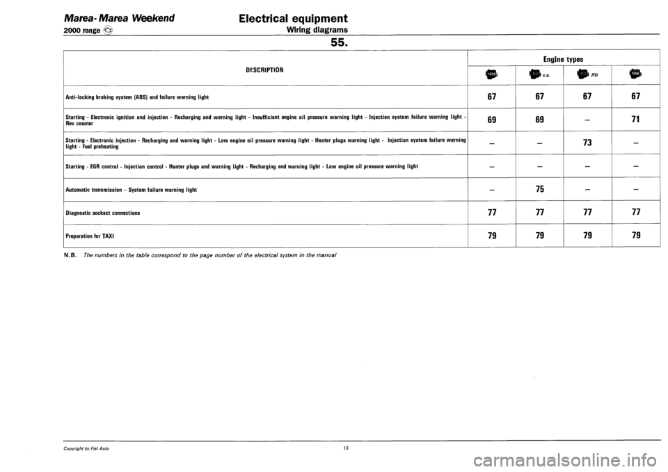
Marea-Marea Weekend Electrical equipment
2000 range (§) Wiring diagrams
55.
DESCRIPTION
Engine types
DESCRIPTION 10i 0) c.a. 01/70
ANTI-LOCKING BRAKING SYSTEM (ABS) AND FAILURE WARNING LIGHT 67 67 67 67
STARTING - ELECTRONIC IGNITION AND INJECTION - RECHARGING AND WARNING LIGHT - INSUFFICIENT ENGINE OIL PRESSURE WARNING LIGHT - INJECTION SYSTEM FAILURE WARNING LIGHT -
REV COUNTER 69 69 — 71
STARTING - ELECTRONIC INJECTION - RECHARGING AND WARNING LIGHT - LOW ENGINE OIL PRESSURE WARNING LIGHT - HEATER PLUGS WARNING LIGHT - INJECTION SYSTEM FAILURE WARNING
LIGHT - FUEL PREHEATING — — 73 —
STARTING - EGR CONTROL - INJECTION CONTROL - HEATER PLUGS AND WARNING LIGHT - RECHARGING AND WARNING LIGHT - LOW ENGINE OIL PRESSURE WARNING LIGHT — — — —
AUTOMATIC TRANSMISSION - SYSTEM FAILURE WARNING LIGHT — 75 — —
DIAGNOSTIC SOCKECT CONNECTIONS 77 77 77 77
PREPARATION FOR TAXI 79 79 79 79
FM.B. The numbers in the table correspond to the page number of the electrical system in the manual
Copyright by Fiat Auto III