heater FIAT MAREA 2000 1.G Workshop Manual
[x] Cancel search | Manufacturer: FIAT, Model Year: 2000, Model line: MAREA, Model: FIAT MAREA 2000 1.GPages: 330
Page 86 of 330
Marea- Marea Weekend 9 \) JTD
2000 range O
Engine
Index
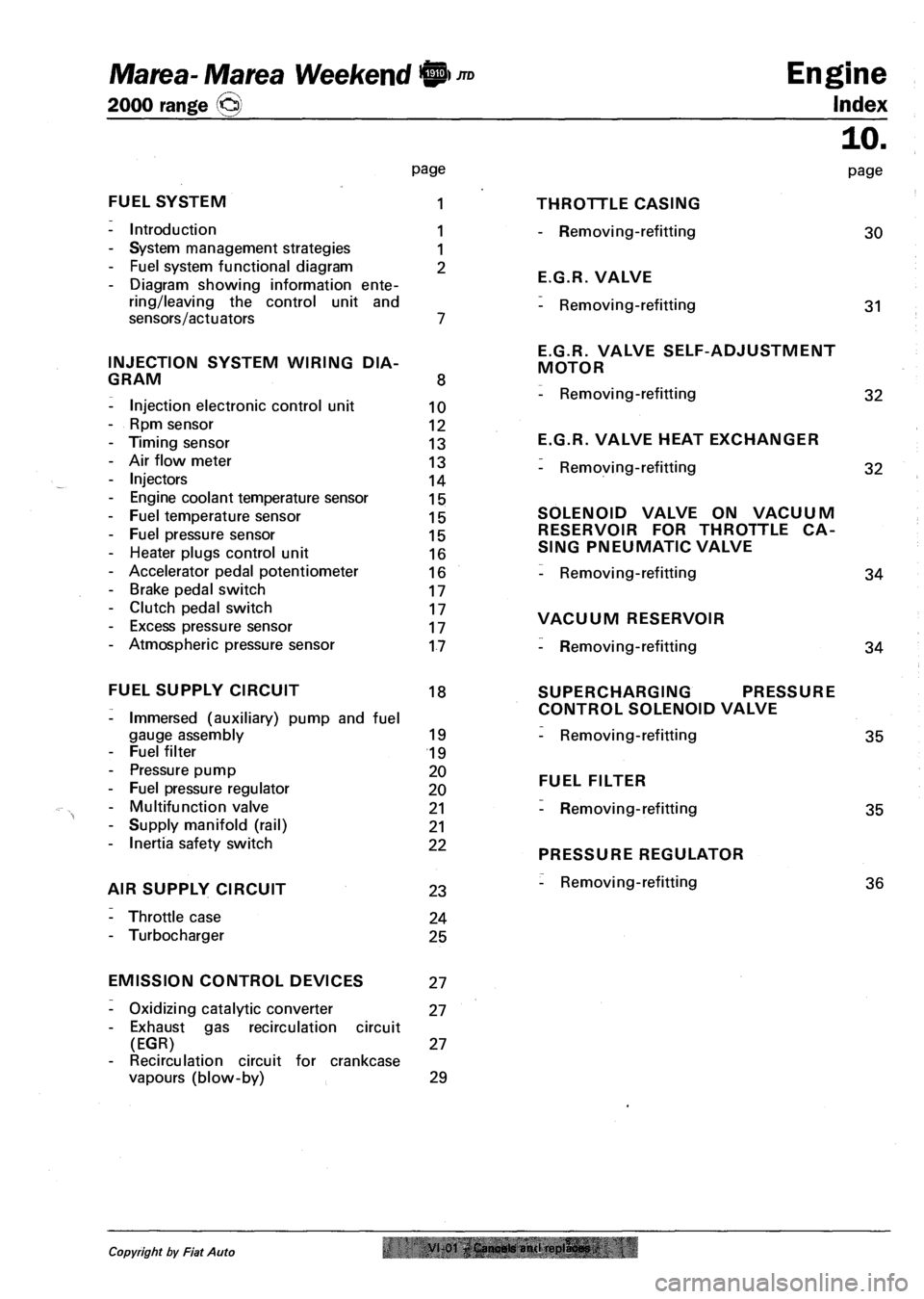
FUEL SYSTEM
- Introduction
- System management strategies
- Fuel system functional diagram
- Diagram showing information ente
ring/leaving the control unit and
sensors/actuators
INJECTION SYSTEM WIRING DIA
GRAM
- Injection electronic control unit
- Rpm sensor
- Timing sensor
- Air flow meter
- Injectors
- Engine coolant temperature sensor
- Fuel temperature sensor
- Fuel pressure sensor
- Heater plugs control unit
- Accelerator pedal potentiometer
- Brake pedal switch
- Clutch pedal switch
- Excess pressure sensor
- Atmospheric pressure sensor
page
1
1
1
2
8
10
12
13
13
14
15
15
15
16
16
17
17
17
17
THROTTLE CASING
- Removing-refitting
E.G.R. VALVE
- Removing-refitting
E.G.R. VALVE SELF-ADJUSTMENT
MOTOR
- Removing-refitting
E.G.R. VALVE HEAT EXCHANGER
- Removing-refitting
SOLENOID VALVE ON VACUUM
RESERVOIR FOR THROTTLE CA
SING PNEUMATIC VALVE
- Removing-refitting
VACUUM RESERVOIR
- Removing-refitting
10.
page
30
31
32
32
34
34
FUEL SUPPLY CIRCUIT 18
- Immersed (auxiliary) pump and fuel
gauge assembly 19
- Fuel filter 19
- Pressure pump 20
- Fuel pressure regulator 20
- Multifunction valve 21
- Supply manifold (rail) 21
- Inertia safety switch 22
AIR SUPPLY CIRCUIT 23
- Throttle case 24
- Turbocharger 25
SUPERCHARGING PRESSURE
CONTROL SOLENOID VALVE
- Removing-refitting 35
FUEL FILTER
- Removing-refitting 35
PRESSURE REGULATOR
- Removing-refitting 36
EMISSION CONTROL DEVICES 27
- Oxidizing catalytic converter 27
- Exhaust gas recirculation circuit
(EGR) 27
- Recirculation circuit for crankcase
vapours (blow-by) 29
Copyright by Fiat Auto VI 01 Cancels anil replaces
Page 95 of 330
Marea- Marea Weekend 9 ™
2000 range ©) Fuel feed system
Engine
10.
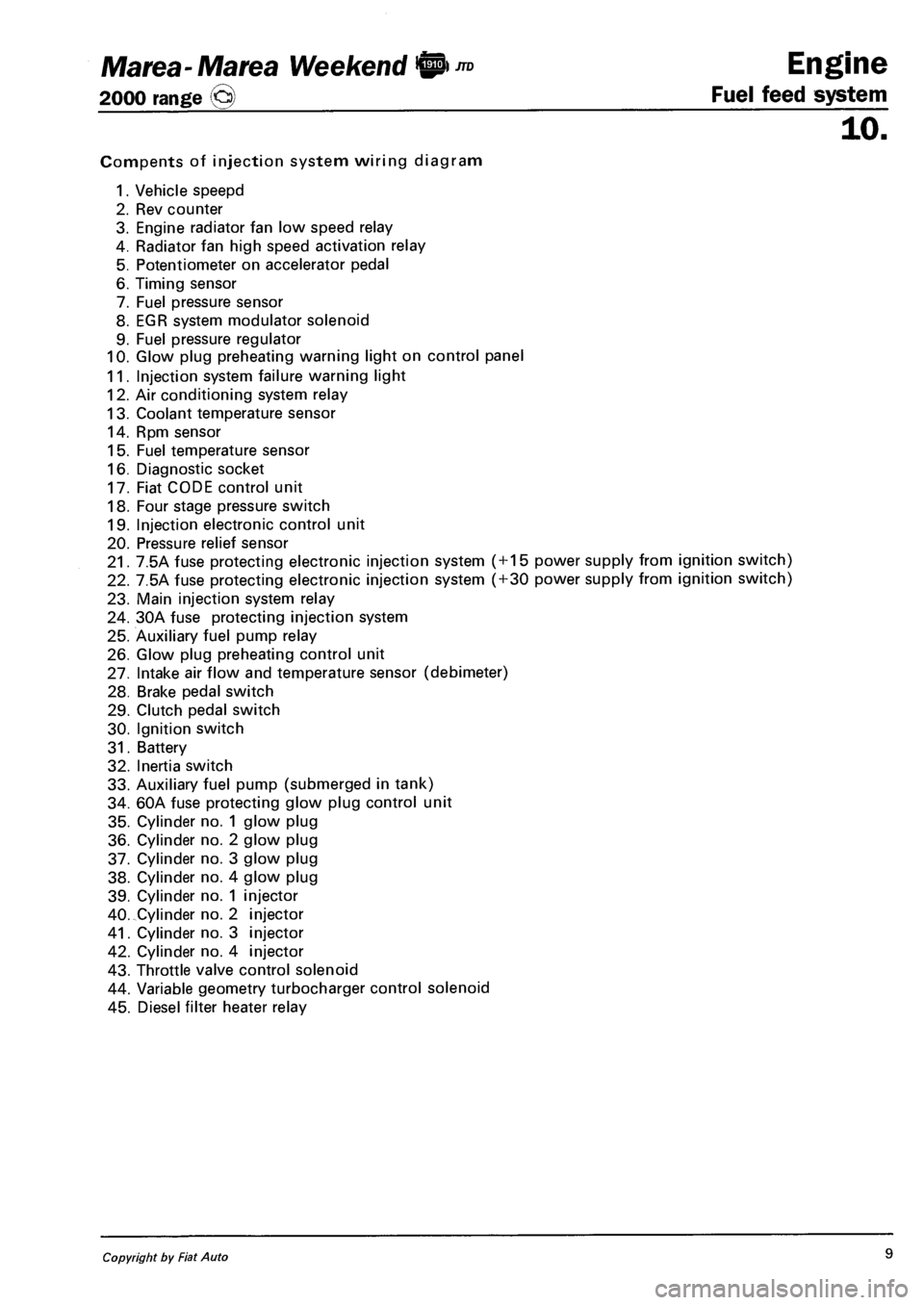
Compents of injection system wiring diagram
1. Vehicle speepd
2. Rev counter
3. Engine radiator fan low speed relay
4. Radiator fan high speed activation relay
5. Potentiometer on accelerator pedal
6. Timing sensor
7. Fuel pressure sensor
8. EGR system modulator solenoid
9. Fuel pressure regulator
10. Glow plug preheating warning light on control panel
11. Injection system failure warning light
12. Air conditioning system relay
13. Coolant temperature sensor
14. Rpm sensor
15. Fuel temperature sensor
16. Diagnostic socket
17. Fiat CODE control unit
18. Four stage pressure switch
19. Injection electronic control unit
20. Pressure relief sensor
21. 7.5A fuse protecting electronic injection system ( + 15 power supply from ignition switch)
22. 7.5A fuse protecting electronic injection system ( + 30 power supply from ignition switch)
23. Main injection system relay
24. 30A fuse protecting injection system
25. Auxiliary fuel pump relay
26. Glow plug preheating control unit
27. Intake air flow and temperature sensor (debimeter)
28. Brake pedal switch
29. Clutch pedal switch
30. Ignition switch
31. Battery
32. Inertia switch
33. Auxiliary fuel pump (submerged in tank)
34. 60A fuse protecting glow plug control unit
35. Cylinder no. 1 glow plug
36. Cylinder no. 2 glow plug
37. Cylinder no. 3 glow plug
38. Cylinder no. 4 glow plug
39. Cylinder no. 1 injector
40. Cylinder no. 2 injector
41. Cylinder no. 3 injector
42. Cylinder no. 4 injector
43. Throttle valve control solenoid
44. Variable geometry turbocharger control solenoid
45. Diesel filter heater relay
Copyright by Fiat Auto 9
Page 97 of 330
Ma tea- Ma tea Weekend !@ ™
2000 range ©
Engine
Fuel feed system
10.
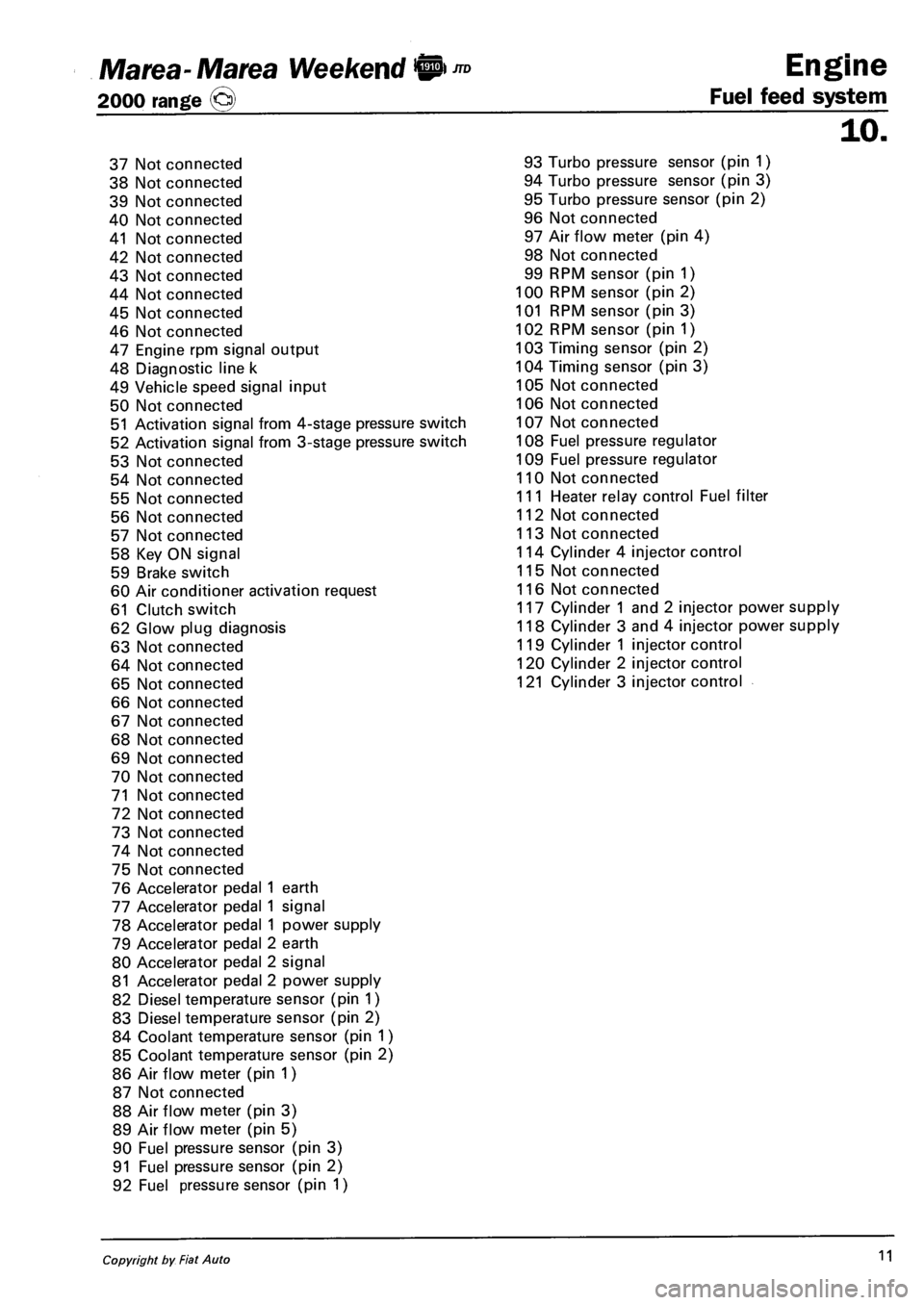
37 Not connected
38 Not connected
39 Not connected
40 Not connected
41 Not connected
42 Not connected
43 Not connected
44 Not connected
45 Not connected
46 Not connected
47 Engine rpm signal output
48 Diagnostic line k
49 Vehicle speed signal input
50 Not connected
51 Activation signal from 4-stage pressure switch
52 Activation signal from 3-stage pressure switch
53 Not connected
54 Not connected
55 Not connected
56 Not connected
57 Not connected
58 Key ON signal
59 Brake switch
60 Air conditioner activation request
61 Clutch switch
62 Glow plug diagnosis
63 Not connected
64 Not connected
65 Not connected
66 Not connected
67 Not connected
68 Not connected
69 Not connected
70 Not connected
71 Not connected
72 Not connected
73 Not connected
74 Not connected
75 Not connected
76 Accelerator pedal 1 earth
77 Accelerator pedal 1 signal
78 Accelerator pedal 1 power supply
79 Accelerator pedal 2 earth
80 Accelerator pedal 2 signal
81 Accelerator pedal 2 power supply
82 Diesel temperature sensor (pin 1)
83 Diesel temperature sensor (pin 2)
84 Coolant temperature sensor (pin 1)
85 Coolant temperature sensor (pin 2)
86 Air flow meter (pin 1)
87 Not connected
88 Air flow meter (pin 3)
89 Air flow meter (pin 5)
90 Fuel pressure sensor (pin 3)
91 Fuel pressure sensor (pin 2)
92 Fuel pressure sensor (pin 1)
93 Turbo pressure sensor (pin 1)
94 Turbo pressure sensor (pin 3)
95 Turbo pressure sensor (pin 2)
96 Not connected
97 Air flow meter (pin 4)
98 Not connected
99 RPM sensor (pin 1)
100 RPM sensor (pin 2)
101 RPM sensor (pin 3)
102 RPM sensor (pin 1)
103 Timing sensor (pin 2)
104 Timing sensor (pin 3)
105 Not connected
106 Not connected
107 Not connected
108 Fuel pressure regulator
109 Fuel pressure regulator
110 Not connected
111 Heater relay control Fuel filter
112 Not connected
113 Not connected
114 Cylinder 4 injector control
115 Not connected
116 Not connected
117 Cylinder 1 and 2 injector power supply
118 Cylinder 3 and 4 injector power supply
119 Cylinder 1 injector control
120 Cylinder 2 injector control
121 Cylinder 3 injector control
Copyright by Fiat Auto 11
Page 99 of 330
Marea- Marea Weekend 9"°
2000 range ©
Engine
Fuel feed system
10.
TIMING SENSOR
The Hall effect sensor is fitted to the cylinder head and faces the camshaft pulley.
An opening on the pulley allows the timing sensor to detect the engine timing position and indicate it to
the injection control unit.
The injection control unit uses the timing sensor signal to detect TDC at the end of compression.
Operation
A semi-condulator layer, through which a current passes, immersed in a magnetic field (lines of force per
pendicular to the direction of the current), produces a difference in power, known as Hall voltage.
If the intensity of the current remains constant, the voltage produced only depends on the intensity of the
magnetic field. The intensity of the field can simply be altered periodically to produce a modulated electri
cal signal. Signal frequency is proportional to the speed with which the magnetic field changes.
To achieve this change, the sensor is crossed by a metal ring (inner part of the pulley) with an opening.
When it moves, the metal part of the ring covers the sensor to magnetic field and the output signal is
therefore low; Conversely, the sensor generates a high signal at the opening when the magnetic field is
present.
This signal, together with the rpm and TDC signals, allows the injection control unit to identify piston po
sition and determine injection point.
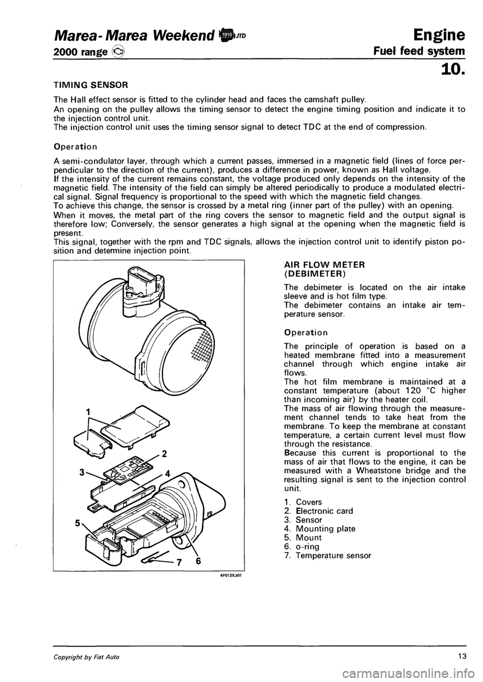
AIR FLOW METER
(DEBIMETER)
The debimeter is located on the air intake
sleeve and is hot film type.
The debimeter contains an intake air tem
perature sensor.
Operation
The principle of operation is based on a
heated membrane fitted into a measurement
channel through which engine intake air
flows.
The hot film membrane is maintained at a
constant temperature (about 120 °C higher
than incoming air) by the heater coil.
The mass of air flowing through the measure
ment channel tends to take heat from the
membrane. To keep the membrane at constant
temperature, a certain current level must flow
through the resistance.
Because this current is proportional to the
mass of air that flows to the engine, it can be
measured with a Wheatstone bridge and the
resulting signal is sent to the injection control
unit.
1. Covers
2. Electronic card
3. Sensor
4. Mounting plate
5. Mount
6. o-ring
7. Temperature sensor
Copyright by Fiat Auto 13
Page 104 of 330
Engine
Fuel feed system
JTD Marea- Marea Weekend 0
2000 range ©
10.
FUEL SUPPLY CIRCUIT
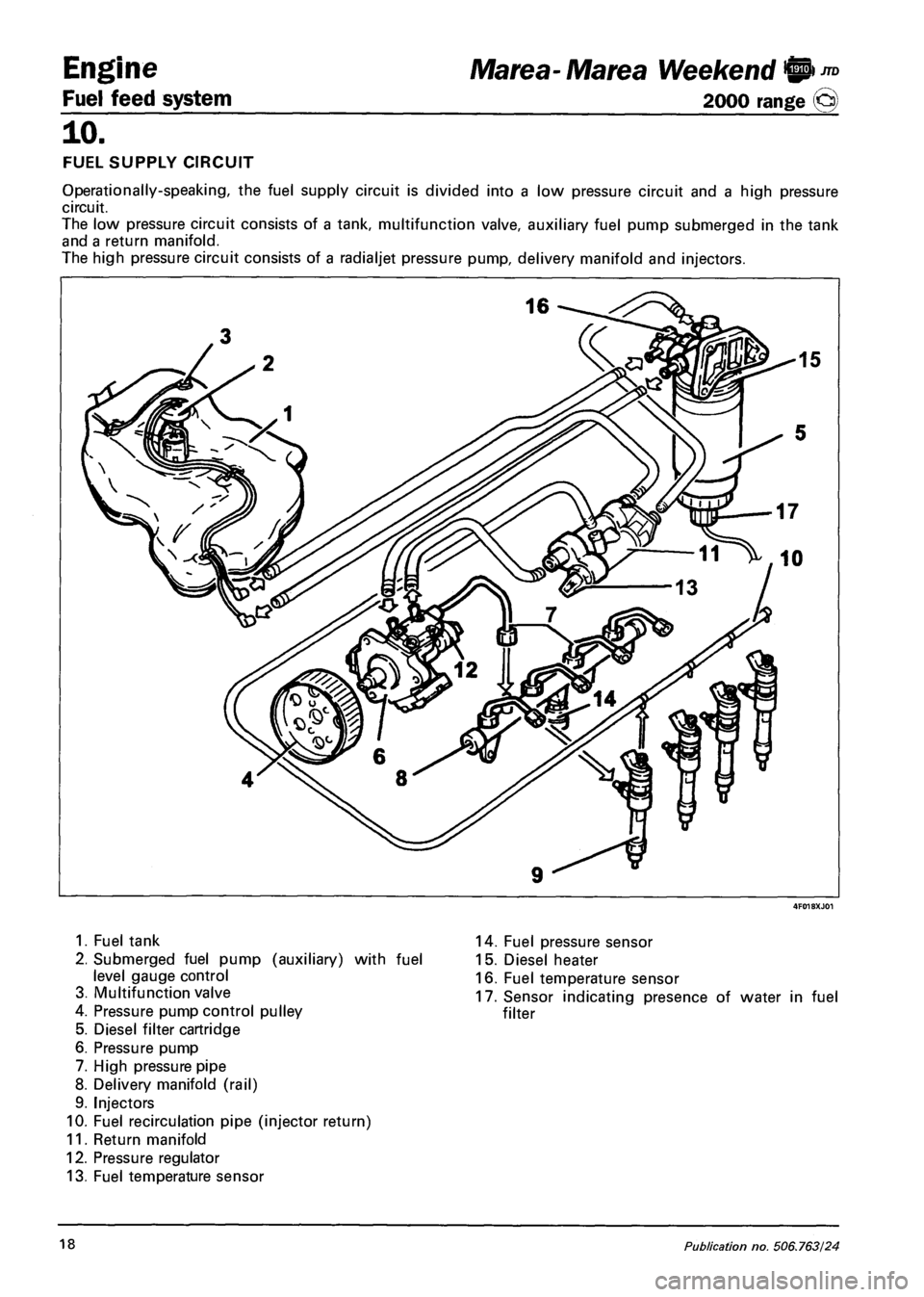
Operationally-speaking, the fuel supply circuit is divided into a low pressure circuit and a high pressure
circuit.
The low pressure circuit consists of a tank, multifunction valve, auxiliary fuel pump submerged in the tank
and a return manifold.
The high pressure circuit consists of a radialjet pressure pump, delivery manifold and injectors.
1. Fuel tank
2. Submerged fuel pump (auxiliary) with fuel
level gauge control
3. Multifunction valve
4. Pressure pump control pulley
5. Diesel filter cartridge
6. Pressure pump
7. High pressure pipe
8. Delivery manifold (rail)
9. Injectors
10. Fuel recirculation pipe (injector return)
11. Return manifold
12. Pressure regulator
13. Fuel temperature sensor
14. Fuel pressure sensor
15. Diesel heater
16. Fuel temperature sensor
17. Sensor indicating presence of water in fuel
filter
18 Publication no. 506.763/24
Page 135 of 330
Marea-Marea Weekend
2000 range Q
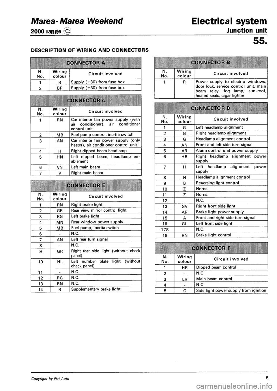
DESCRIPTION OF WIRING AND CONNECTORS
CONNECTOR A
N.
No.
Wiring
colour Circuit involved
1 R Supply (+30) from fuse box
2 BR Supply (+30) from fuse box
CONNECTOR c
N. No.
Wiring colour Circuit involved
1 RN Car interior fan power supply (with
air conditioner), air conditioner
control unit
2 MB Fuel pump control, inertia switch
3 AN Car interior fan power supply (only heater), air conditioner control unit
4 H Right dipped beam headlamp
5 HN Left dipped beam, headllamp en
ablement
6 VN Left main beam
7 V Right main beam
CONNECTOR E
N.
No.
Wiring colour Circuit involved
1 RN Right brake light
2 GR Rear view mirror control light
3 RG Left brake light
4 MN Rear window power supply
5 MB Fuel pump, inertia switch
6 -N.C.
7 AN Left rear turn signal
8 -N.C.
9 GR Right rear side light (without check
panel)
10 HL Left number plate light (without
check panel)
11 -N.C.
12 RG N.C.
13 RN N.C.
14 R Supplementary brake light
Electrical system
Junction unit
55.
CONNECTOR B
N. No.
Wiring
colour Circuit involved
1 R Power supply to electric windows, door lock, service control unit, main beam relay, fog lamp, sun-roof, heated seats, cigar lighter
CONNECTOR D
N.
No.
Wiring colour Circuit involved
1 G Left headlamp alignment
2 G Right headlamp alignment
3 G Headlamp alignment control
4 AN Front and left side turn signal
5 AR Alarm control unit power supply
6 HB Right headlamp alignment power
supply
7 H Left headlamp alignment power
supply
8 H Headlamp alignment control
9 B Reversing light control
10 Z Horns.
11 Z Horns.
12 -N.C.
13 GV Right front side light
14 AR Brake light power supply
15 A Front and right side turn signal
16 GL Left front side light
17S -N.C.
18 RN Brake light control
CONNECTOR F
N.
No.
Wiring colour Circuit involved
1 HR Dipped beam control
2 -N.C.
3 LR Main beam control
4 -N.C.
5 G Side light power supply from ignition
Copyright by Fiat Auto 5
Page 137 of 330
Marea-Marea Weekend Electrical system
2000 range @ Junction unit
55.
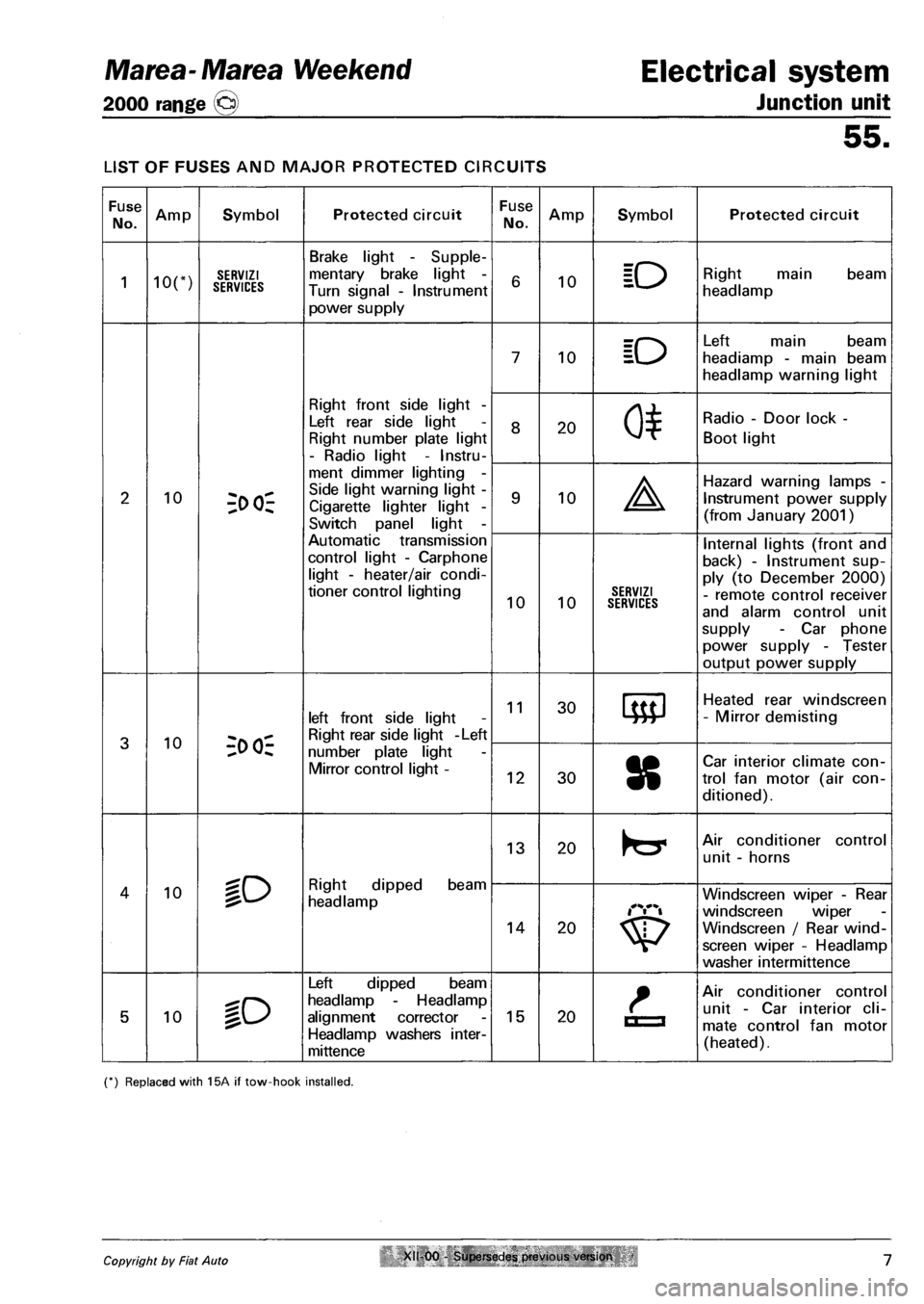
LIST OF FUSES AND MAJOR PROTECTED CIRCUITS
Fuse
No. Amp Symbol Protected circuit Fuse
No. Amp Symbol Protected circuit
1 ion SERVIZI SERVICES
Brake light - Supple
mentary brake light -
Turn signal - Instrument
power supply
6 10 ID Right main beam
headlamp
7 10 ID
Left main beam
headiamp - main beam
headlamp warning light
Right front side light -
Left rear side light
Right number plate light
- Radio light - Instru
8 20 0*
Radio - Door lock -
Boot light
2 10 3>
Side light warning light -
Cigarette lighter light -
Switch panel light -
9 10 A
Hazard warning lamps -
Instrument power supply
(from January 2001)
Automatic transmission
control light - Carphone
light - heater/air condi
tioner control lighting 10 10 SERVIZI SERVICES
Internal lights (front and
back) - Instrument sup
ply (to December 2000)
- remote control receiver
and alarm control unit
supply - Car phone
power supply - Tester
output power supply
3 10 -;o oi-
left front side light
Right rear side light -Left
11 30 Heated rear windscreen
- Mirror demisting
3 10 -;o oi-number plate light
Mirror control light -12 30 8
Car interior climate con
trol fan motor (air con
ditioned).
lO Right dipped beam
headlamp
13 20 Air conditioner control
unit - horns
4 10 lO Right dipped beam
headlamp
14 20
Windscreen wiper - Rear
windscreen wiper
Windscreen / Rear wind
screen wiper - Headlamp
washer intermittence
5 10 %o
Left dipped beam
headlamp - Headlamp
alignment corrector
Headlamp washers inter-
mittence
15 20 La
Air conditioner control
unit - Car interior cli
mate control fan motor
(heated).
(*) Replaced with 15A if tow-hook installed.
Copyright by Fiat Auto XII 00 - Supersedes previous version 7
Page 140 of 330
Electrical equipment Marea-Marea Weekend
Location of components on the car 2000 range (§)
55.
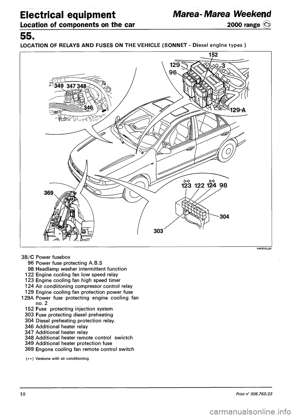
LOCATION OF RELAYS AND FUSES ON THE VEHICLE (BONNET - Diesel engine types )
152
3B/C Power fusebox
96 Power fuse protecting A.B.S
98 Headlamp washer intermittent function
122 Engine cooling fan low speed relay
123 Engine cooling fan high speed timer
124 Air condiitoning compressor control relay
129 Engine cooling fan protection power fuse
129A Power fuse protecting engine cooling fan
no. 2
152 Fuse protecting injection system
303 Fuse protecting diesel preheating
304 Diesel preheating protection relay.
346 Additional heater relay
347 Additional heater relay
348 Additional heater remote control swictch
349 Additional heater protection fuse
369 Engone cooling fan remote control switch
(••) Versions with air conditioning
10 Print n° 506.763/23
Page 141 of 330
Marea-Marea Weekend Electrical equipment
2000 range (§) Location of components on the car
55.
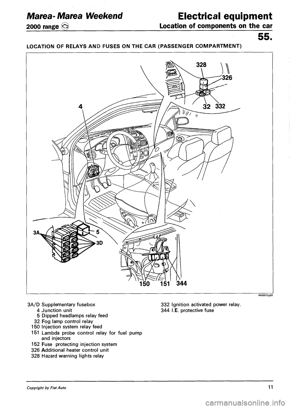
LOCATION OF RELAYS AND FUSES ON THE CAR (PASSENGER COMPARTMENT)
3A/D Supplementary fusebox 332 Ignition activated power relay.
4 Junction unit 344 I.E. protective fuse
5 Dipped headlamps relay feed
32 Fog lamp control relay
150 Injection system relay feed
151 Lambda probe control relay for fuel pump
and injectors
152 Fuse protecting injection system
326 Additional heater control unit
328 Hazard warning lights relay
Copyright by Fiat Auto 11
Page 144 of 330
Electrical equipment
Instrument panel
Marea-Marea Weekend
2000 range ©
55.
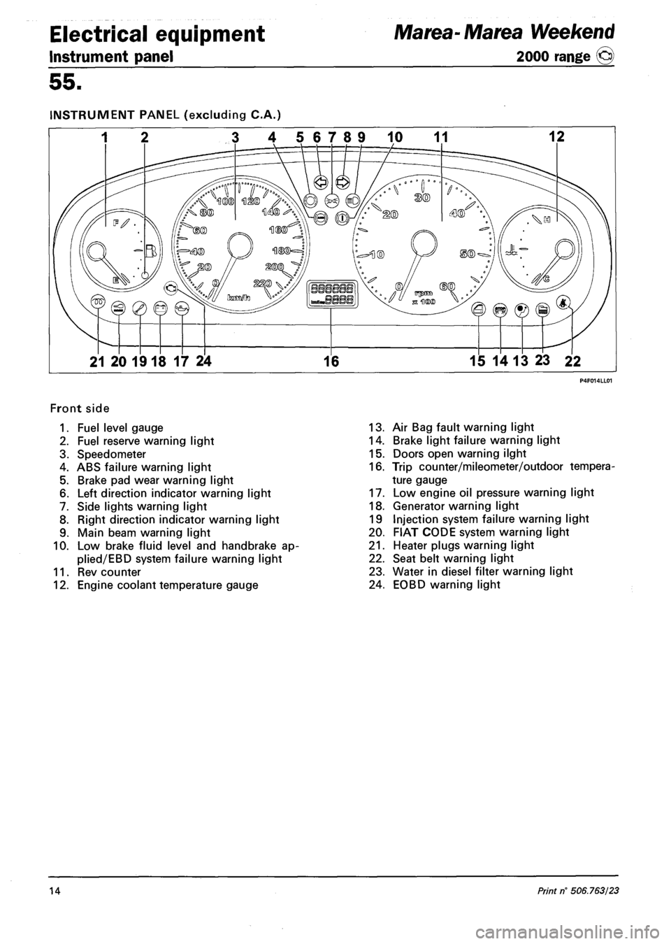
INSTRUMENT PANEL (excluding C.A.)
3 4 56789 10 11 12
21 20 1918 17 24 16 15 14 13 23 22
Front side
1. Fuel level gauge
2. Fuel reserve warning light
3. Speedometer
4. ABS failure warning light
5. Brake pad wear warning light
6. Left direction indicator warning light
7. Side lights warning light
8. Right direction indicator warning light
9. Main beam warning light
10. Low brake fluid level and handbrake ap-
plied/EBD system failure warning light
11. Rev counter
12. Engine coolant temperature gauge
13. Air Bag fault warning light
14. Brake light failure warning light
15. Doors open warning ilght
16. Trip counter/mileometer/outdoor tempera
ture gauge
17. Low engine oil pressure warning light
18. Generator warning light
19 Injection system failure warning light
20. FIAT CODE system warning light
21. Heater plugs warning light
22. Seat belt warning light
23. Water in diesel filter warning light
24. EOBD warning light
14 Print rf 506.763/23