start engine FIAT MAREA 2000 1.G Workshop Manual
[x] Cancel search | Manufacturer: FIAT, Model Year: 2000, Model line: MAREA, Model: FIAT MAREA 2000 1.GPages: 330
Page 11 of 330
Introduction
Performance - Fuel consumption
Marea-Marea Weekend
2000 range ©
OO.o
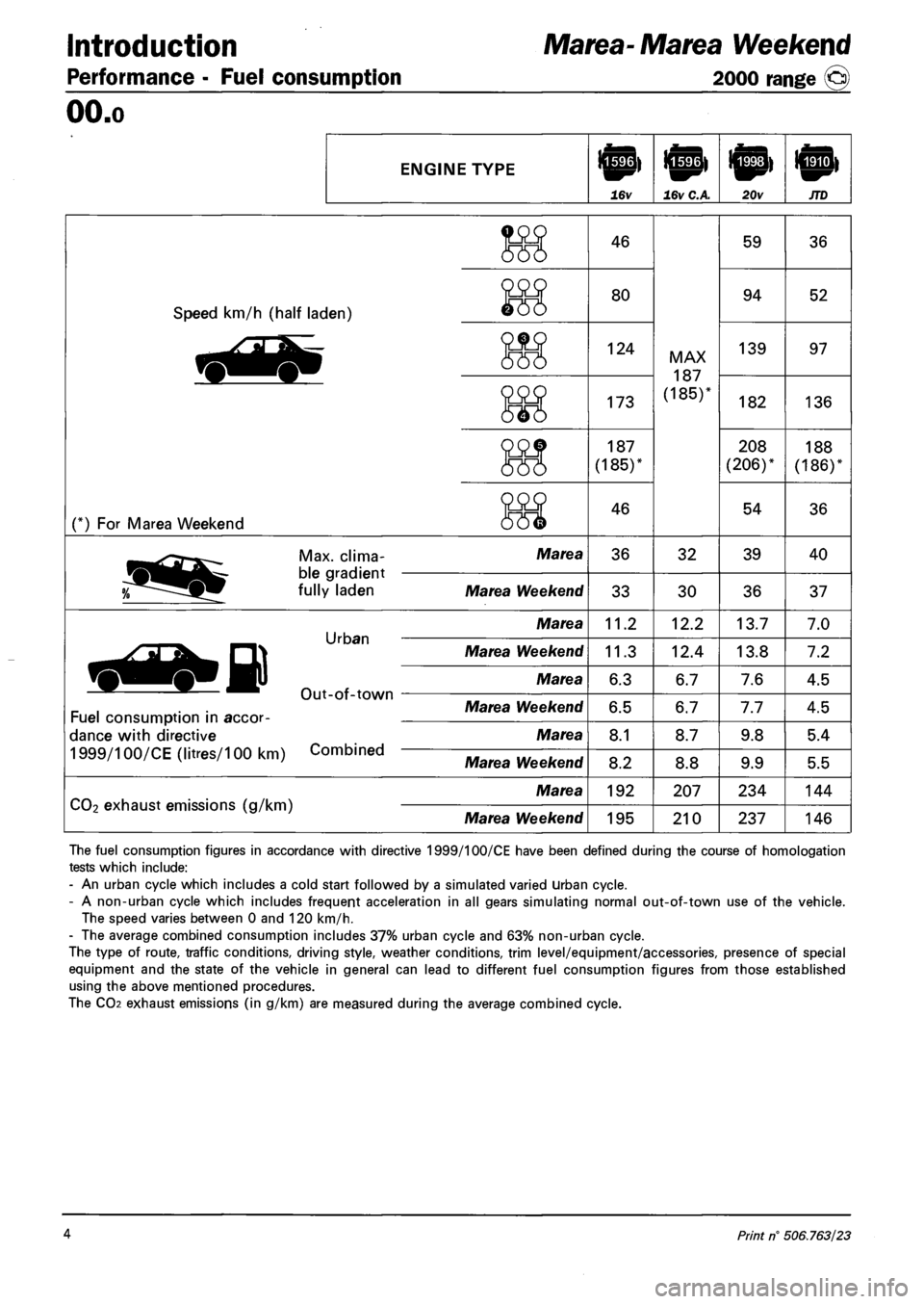
ENGINE TYPE
16v 16v C.A 20v JTD
Speed km/h (half laden)
(*) For Marea Weekend
46
80
124
173
187
(185)'
46
MAX
187
(185)*
59
94
139
182
208
(206)*
54
Max. clima-
ble gradient
fully laden
Marea 36 32 39
Marea Weekend 33 30 36
Urban
Out-of-town
Marea 11.2 12.2 13.7
Marea Weekend 11.3 12.4 13.8
Marea 6.3 6.7 7.6
Fuel consumption in accor
dance with directive
1999/100/CE (litres/100 km) Combined
Marea Weekend 6.5 6.7 7.7
Marea 8.1 8.7 9.8
Marea Weekend 8.2 8.8 9.9
CO2 exhaust emissions (g/km)
Marea 192 207 234
Marea Weekend 195 210 237
The fuel consumption figures in accordance with directive 1999/100/CE have been defined during the course of homologation
tests which include:
- An urban cycle which includes a cold start followed by a simulated varied urban cycle.
- A non-urban cycle which includes frequent acceleration in all gears simulating normal out-of-town use of the vehicle.
The speed varies between 0 and 120 km/h.
- The average combined consumption includes 37% urban cycle and 63% non-urban cycle.
The type of route, traffic conditions, driving style, weather conditions, trim level/equipment/accessories, presence of special
equipment and the state of the vehicle in general can lead to different fuel consumption figures from those established
using the above mentioned procedures.
The CO2 exhaust emissions (in g/km) are measured during the average combined cycle.
4 Print n° 506.763/23
Page 33 of 330
Technical Data Marea-Marea Weekend
Engine: cooling system • fuel system 2000 range (§)
OO.io
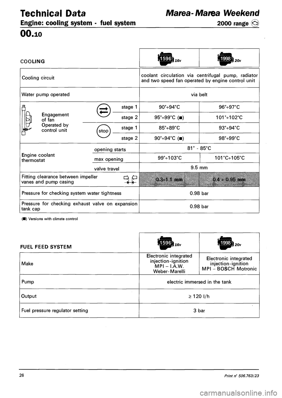
COOLING
Cooling circuit coolant circulation via centrifugal pump, radiator
and two speed fan operated by engine control unit
Water pump operated via belt
fl (^+\ STA9E 1 90°H-94°C 96°+97T
^ Engagement vj^/ ?
of fan stage Z 95°+99°C (•) 101+102°C
\f Operated by v .
control unit (s\oo\ 9 85V89X 93°-H94T
• v y
v—' stage 2 90°+94°C (•) 98+99T
opening starts 81° - 85°C
Engine coolant
thermostat rnax opening 99+103°C 101DC+105'C
valve travel 9.5 mm
Fitting clearance between impeller p
vanes and pump casing j |< 0.3:1.1 mm 0.4 : 0.95 mm
Pressure for checking system water tightness 0.98 bar
Pressure for checking exhaust valve on expansion
tank cap 0.98 bar
(•) Versions with climate control
FUEL FEED SYSTEM
Make
Electronic integrated
injection-ignition
MPI - I.A.W.
Weber-Marelli
Electronic integrated
injection-ignition
MPI - BOSCH Motronic
Pump electric immersed in the tank
Output > 120 l/h
Fuel pressure regulator setting 3 bar
26 Print n° 506.763/23
Page 50 of 330
Technical Data
Front suspension
00.44
ENGINE TYPE h|p>jrD
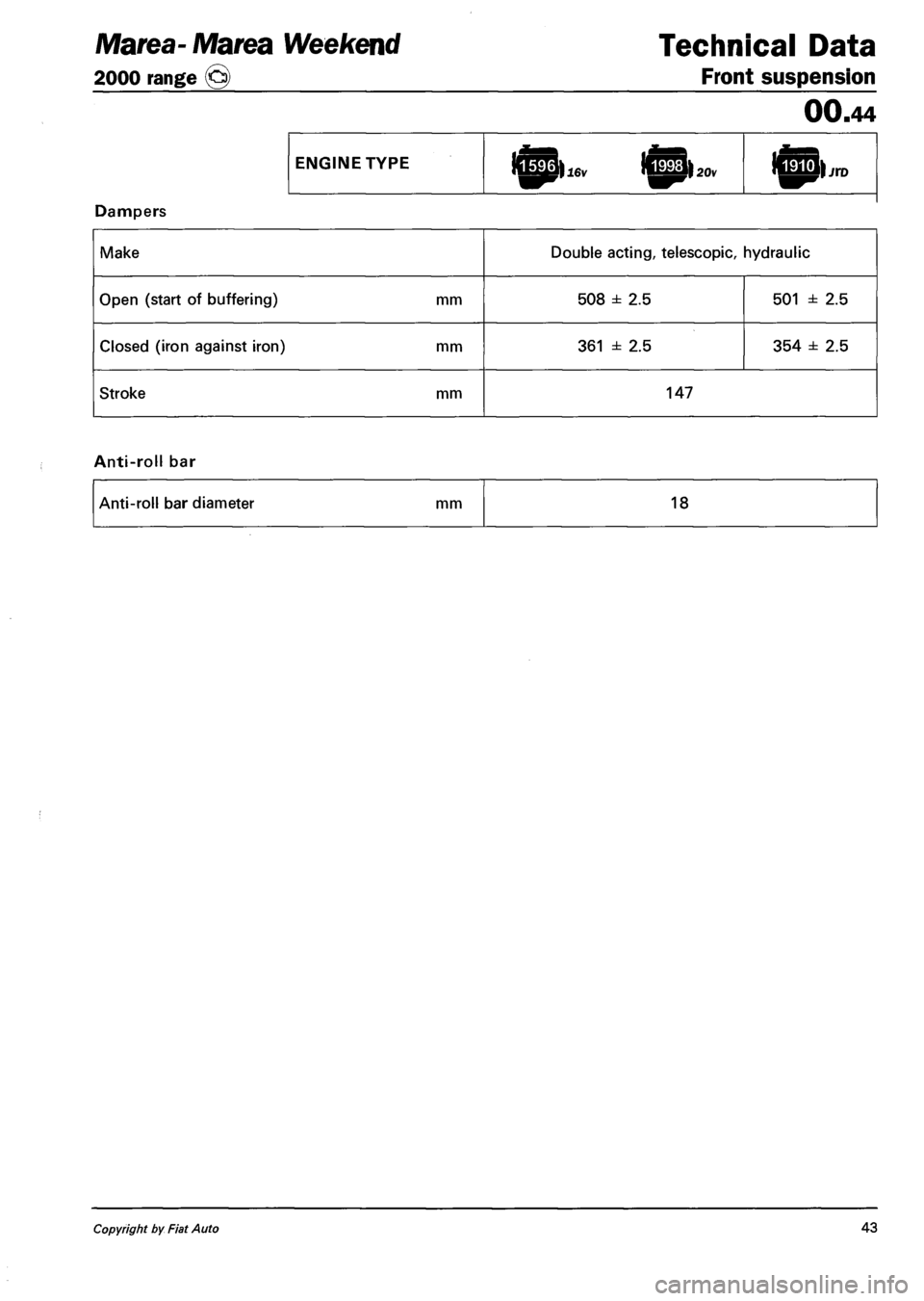
Dampers
Make Double acting, telescopic, hydraulic
Open (start of buffering) mm 508 ± 2.5 501 ± 2.5
Closed (iron against iron) mm 361 ± 2.5 354 ± 2.5
Stroke mm 147
Anti-roll bar
Anti-roll bar diameter mm 18
Marea- Marea Weekend
2000 range ©
Copyright by Fiat Auto 43
Page 51 of 330
Technical Data Marea
Rear suspension 2000 range (§)
00.44
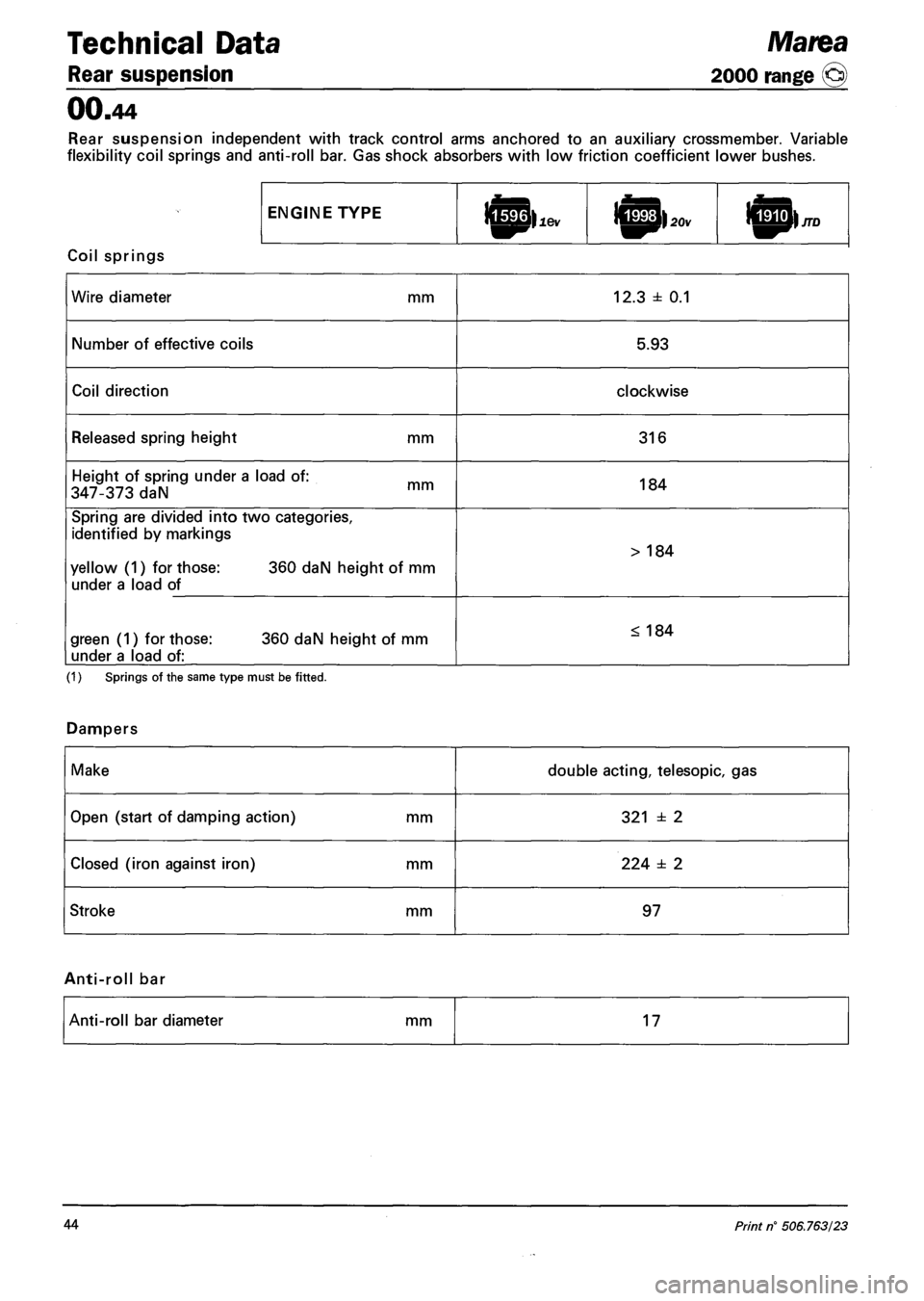
Rear suspension independent with track control arms anchored to an auxiliary crossmember. Variable
flexibility coil springs and anti-roll bar. Gas shock absorbers with low friction coefficient lower bushes.
ENGINE TYPE lopi lev ICphov
Coil springs
Wire diameter mm 12.3 ± 0.1
Number of effective coils 5.93
Coil direction clockwise
Released spring height mm 316
Height of spring under a load of:
347-373 daN mm 184
Spring are divided into two categories,
identified by markings
yellow (1) for those: 360 daN height of mm
under a load of
> 184
green (1) for those: 360 daN height of mm
under a load of:
< 184
(1) Springs of the same type must be fitted.
Dampers
Make double acting, telesopic, gas
Open (start of damping action) mm 321 ± 2
Closed (iron against iron) mm 224 ± 2
Stroke mm 97
Anti-roll bar
Anti-roll bar diameter mm 17
44 Print n° 506.763/23
Page 52 of 330
Marea Weekend Technical Data
2000 range o Rear suspension
00.44
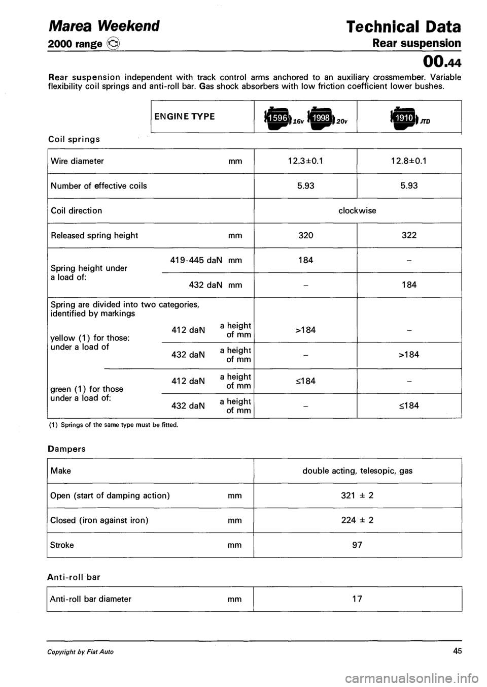
Rear suspension independent with track control arms anchored to an auxiliary crossmember. Variable
flexibility coil springs and anti-roll bar. Gas shock absorbers with low friction coefficient lower bushes.
ENGINE TYPE
Coil springs
Wire diameter mm 12.3±0.1 12.8±0.1
Number of effective coils 5.93 5.93
Coil direction clockwise
Released spring height mm 320 322
419-445 daN mm
Spring height under
184 -
a load of:
432 daN mm -184
Spring are divided into two categories,
identified by markings
412 daN
yellow (1) for those: oT mm
>184 _
under a load of hpinht
432 daN a
of mm
->184
412 daN aJS* green (1) for those ot mm
<184 -
under a load of: _ hpiflht 432 daN a "eif£J ot mm -<184
(1) Springs of the same type must be fitted.
Dampers
Make double acting, telesopic, gas
Open (start of damping action) mm 321 ± 2
Closed (iron against iron) mm 224 ± 2
Stroke mm 97
Anti-roll bar
Anti-roll bar diameter mm 17
Copyright by Fiat A uto 45
Page 63 of 330
Marengo 0 ™ Technical Data
2000 range Suspension and wheels
OO.o
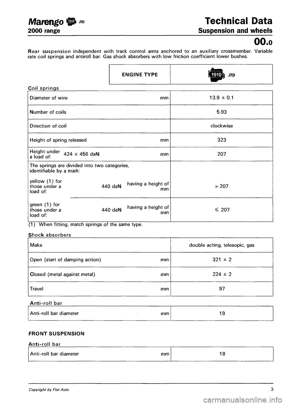
Rear suspension independent with track control arms anchored to an auxiliary crossmember. Variable
rate coil springs and antiroll bar. Gas shock absorbers with low friction coefficient lower bushes.
ENGINE TYPE
Coil springs
Diameter of wire mm 13.9 ± 0.1
Number of coils 5.93
Direction of coil clockwise
Height of spring released mm 323
Height under 424 ± 456 daN mm a load of : 207
The springs are divided into two categories,
identifiable by a mark:
XX°l 440 daN having a heigh, of i -i x mm load of:
> 207
green (1) for having a height of those under a 440 daN a a i J x. mm load of:
^ 207
(1) When fitting, match springs of the same type.
Shock absorbers
Make double acting, telesopic, gas
Open (start of damping action) mm 321 ± 2
Closed (metal against metal) mm 224 ± 2
Travel mm 97
Anti-roll bar
Anti-roll bar diameter mm 19
FRONT SUSPENSION
Anti-roll bar
Anti-roll bar diameter mm 18
Copyright by Fiat Auto 3
Page 66 of 330
Marea Weekend 9 mnoocv Introduction
2000 range @> Identification data - Performance - Fuel consumption
OO.o
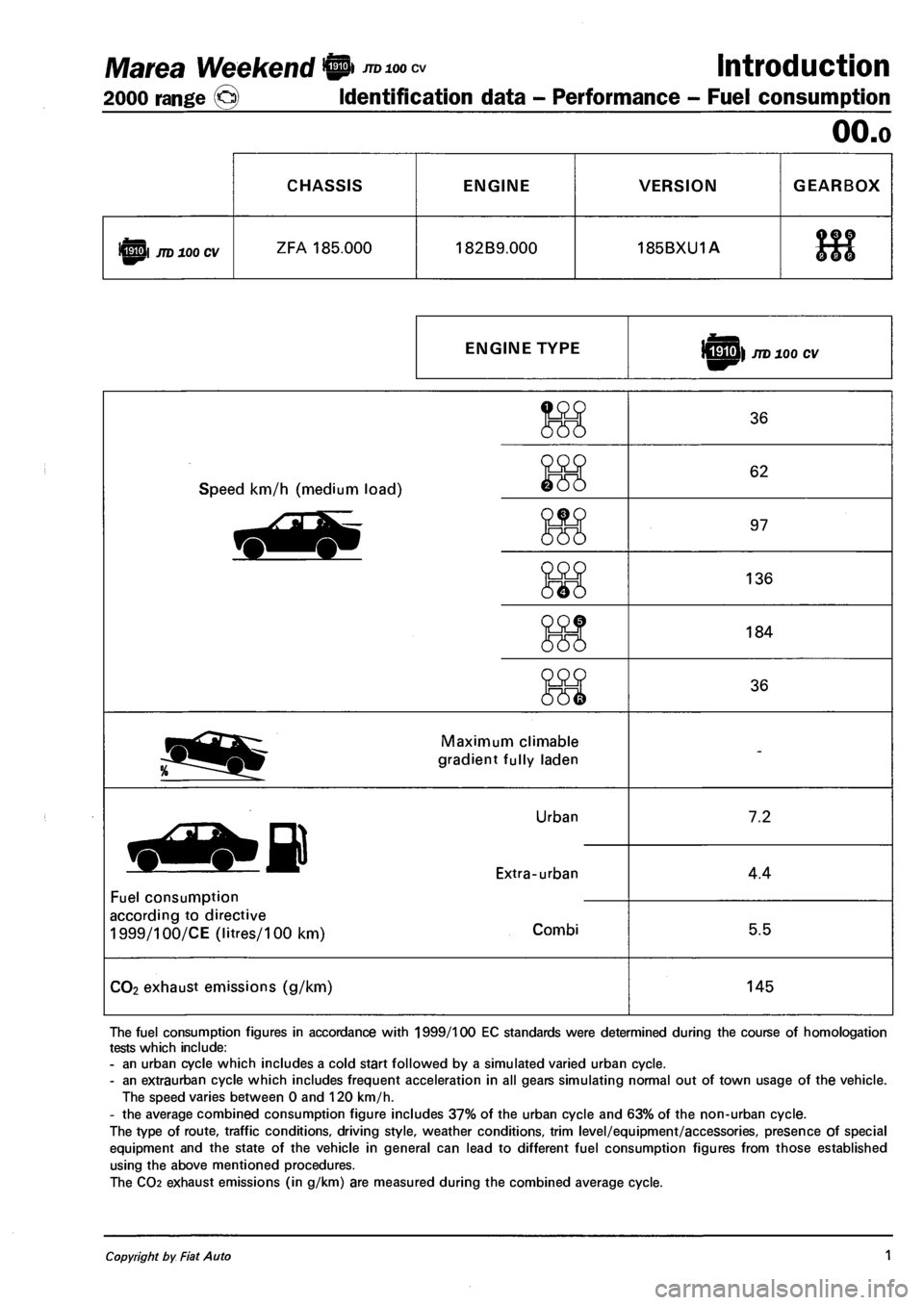
CHASSIS ENGINE VERSION GEARBOX
iQpl JTD 100 CV ZFA 185.000 182B9.000 185BXU1A 9f ?
666
ENGINE TYPE sHU) JTD 100 CV
Speed km/h (medium load)
36
62
97
136
184
36
Maximum climable
gradient fully laden
Fuel consumption
according to directive
1999/100/CE (litres/100 km)
Urban
Extra-urban
Combi
7.2
4.4
5.5
CO2 exhaust emissions (g/km) 145
The fuel consumption figures in accordance with 1999/100 EC standards were determined during the course of homologation
tests which include:
- an urban cycle which includes a cold start followed by a simulated varied urban cycle.
- an extraurban cycle which includes frequent acceleration in all gears simulating normal out of town usage of the vehicle.
The speed varies between 0 and 120 km/h.
- the average combined consumption figure includes 37% of the urban cycle and 63% of the non-urban cycle.
The type of route, traffic conditions, driving style, weather conditions, trim level/equipment/accessories, presence of special
equipment and the state of the vehicle in general can lead to different fuel consumption figures from those established
using the above mentioned procedures.
The CO2 exhaust emissions (in g/km) are measured during the combined average cycle.
Copyright by Fiat Auto 1
Page 89 of 330
Ma tea- Marea Weekend 9 ™
2000 range (Q) Fuel feed system
Engine
10.
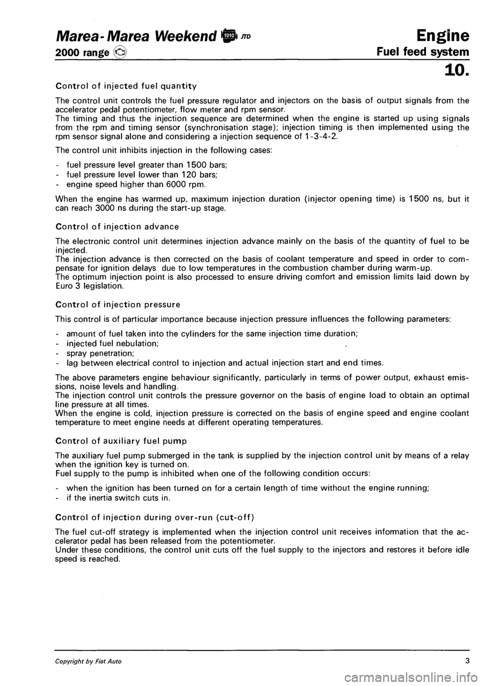
Control of injected fuel quantity
The control unit controls the fuel pressure regulator and injectors on the basis of output signals from the
accelerator pedal potentiometer, flow meter and rpm sensor.
The timing and thus the injection sequence are determined when the engine is started up using signals
from the rpm and timing sensor (synchronisation stage); injection timing is then implemented using the
rpm sensor signal alone and considering a injection sequence of 1 -3-4-2.
The control unit inhibits injection in the following cases:
- fuel pressure level greater than 1500 bars;
- fuel pressure level lower than 120 bars;
- engine speed higher than 6000 rpm.
When the engine has warmed up, maximum injection duration (injector opening time) is 1500 ns, but it
can reach 3000 ns during the start-up stage.
Control of injection advance
The electronic control unit determines injection advance mainly on the basis of the quantity of fuel to be
injected.
The injection advance is then corrected on the basis of coolant temperature and speed in order to com
pensate for ignition delays due to low temperatures in the combustion chamber during warm-up.
The optimum injection point is also processed to ensure driving comfort and emission limits laid down by
Euro 3 legislation.
Control of injection pressure
This control is of particular importance because injection pressure influences the following parameters:
- amount of fuel taken into the cylinders for the same injection time duration;
- injected fuel nebulation;
- spray penetration;
- lag between electrical control to injection and actual injection start and end times.
The above parameters engine behaviour significantly, particularly in terms of power output, exhaust emis
sions, noise levels and handling.
The injection control unit controls the pressure governor on the basis of engine load to obtain an optimal
line pressure at all times.
When the engine is cold, injection pressure is corrected on the basis of engine speed and engine coolant
temperature to meet engine needs at different operating temperatures.
Control of auxiliary fuel pump
The auxiliary fuel pump submerged in the tank is supplied by the injection control unit by means of a relay
when the ignition key is turned on.
Fuel supply to the pump is inhibited when one of the following condition occurs:
- when the ignition has been turned on for a certain length of time without the engine running;
- if the inertia switch cuts in.
Control of injection during over-run (cut-off)
The fuel cut-off strategy is implemented when the injection control unit receives information that the ac
celerator pedal has been released from the potentiometer.
Under these conditions, the control unit cuts off the fuel supply to the injectors and restores it before idle
speed is reached.
Copyright by Fiat Auto 3
Page 90 of 330
Fuel feed system
Engine Marea- Marea Weekend 9 ™
2000 range (Q)
10.
Control of idle speed
On the basis of signals from the rpm sensor and engine coolant temperature sensor, the injection control
unit controls the pressure governor and alters the injector control times to maintain idle speed stable at all
times.
Under certain conditions, the idle speed control unit also considers battery voltage.
Control of maximum speed limitation
According to rpm level, the injection control unit limits maximum speed by means of two types of inter
vention:
- as maximum speed approaches, it reduces the amount of fuel injected to reduce line pressure;
- when maximum speed is exceeded, it inhibits operation of the auxiliary pump and injectors.
Control of maximum torque limitation
On the basis of rpm level, the injection control unit computes limit torque and maximum permitted fume
index parameters on the basis of predefined, stored maps.
It then corrects the above parameters using engine coolant temperature and car speed data. The resulting
values are then used to modulate the amount of fuel to be injected by adjusting the pressure regulator and
injectors.
Control of fuel temperature
The injection control uint is kept constantly informed of fuel temperature by a sensor on the return mani
fold.
If fuel temperature exceeds a set value (about 110 °C), the control unit reduces line pressure by adjusting
the pressure governor, leaving injection times unaltered.
Control of coolant temperature
The injection control unit is constantly informed of coolant temperature by a sensor on the thermostat.
If engine coolant temperature or air conditioning fluid pressure exceeds certain levels, the control unit
performs the following actions:
- It reduces the amount of fuel injected by adjusting the pressure governor and injectors (power reduc
tion);
- it controls the engine radiator cooling fan.
Control of glow plugs
The injection control unit controls operation of the glow plug preheating control unit to bring the tem
perature in the combution chambers up to levels that promote fuel self-ignition and thus make start-up
easier.
The control unit controls the operation of the glow plug control unit for a certain time both before (pre
heating) and after (postheating) engine start-up and also controls activation of the warning light on the
control panel.
Preheating, postheating and glow plug warning light activation times vary according to engine coolant
temperature.
4 Publication no. 506.763/24
Page 92 of 330
Fuel feed system
Engine Marea- Marea Weekend © ™
2000 range @
10.
The control unit autodiagnostic system checks the signals coming from the sensors and compares them
with the figures allowed:
- signalling faults during starting
- warning light on for 4 seconds indicates test stage
- warning light off after 4 seconds indicates no fault with components that could alter the pollution con
trol standard figures
- warning light on after 4 seconds indicates fault.
- signalling faults during operation
- warning light on indicates fault
- warning light off indicates no fault with components that could alter the pollution control standard fig
ures.
- recovery
- from time to time, the control unit defines the type of recovery according to the components which are
faulty
- the recovery parameters are managed by components which are not faulty.
Control of cylinder balancing during idling
According to the signals coming from the sensors, the injection control unit controls the idle speed torque,
altering the injector operating times.
Control of irregular operation
Depending on the signals coming from the sensors, the injection control unit corrects the amount of fuel
to be injected in order to improve driveability and reduce jerking whilst driving.
The correction is achieved through the fuel pressure regulator and by varying the injector operating times.
Control of electrical balance
According to the battery voltage, the injection control unit alters the idle speed, to guarantee a sufficient
current supply from the alternator in situations where the consumers are absorbing a great deal of power.
The variation in the idle speed is achived by regulating the fuel pressure and altering the injector operat
ing times.
VGT variable geometry turbocharger control (1910 JTD 110 CV)
The injection control unit processes the signal coming from the supercharging sensor, at the various en
gine operating speeds, and determines the quantity of fuel to be injected, acting on the fuel pressure
regulator and the injector opening times.
In addition, through the solenoid valve, the control unit regulates the geometry of the turbine in order to
ensure optimum performance in all operating conditions.
Turbocharger waste gate valve control (1910 JTD 100 CV)
At the various engine operating speeds, the injection control unit processes the signal coming from the
supercharging sensor and determines the amount of fuel to inject, acting on the fuel pressure regulator
and the injector opening times.
In addition, the control unit controls the opening of the turbocharger waste gate valve, via the solenoid
valve, in order to ensure excellent performance in all operating conditions.
Control of throttle closing when engine is switched off
When the engine is switched off (ignition key in OFF position) the injection control unit closes the throt
tle valve located on the air intake duct via the special solenoid valve.
This action makes it possible to limit the tiresome shuddering of the engine whilst it is switching off.
6 .i. V!-01-.Cancelftand replaces Print n° 506.763/25