start engine FIAT MAREA 2000 1.G User Guide
[x] Cancel search | Manufacturer: FIAT, Model Year: 2000, Model line: MAREA, Model: FIAT MAREA 2000 1.GPages: 330
Page 100 of 330
Engine
Fuel feed system
10.
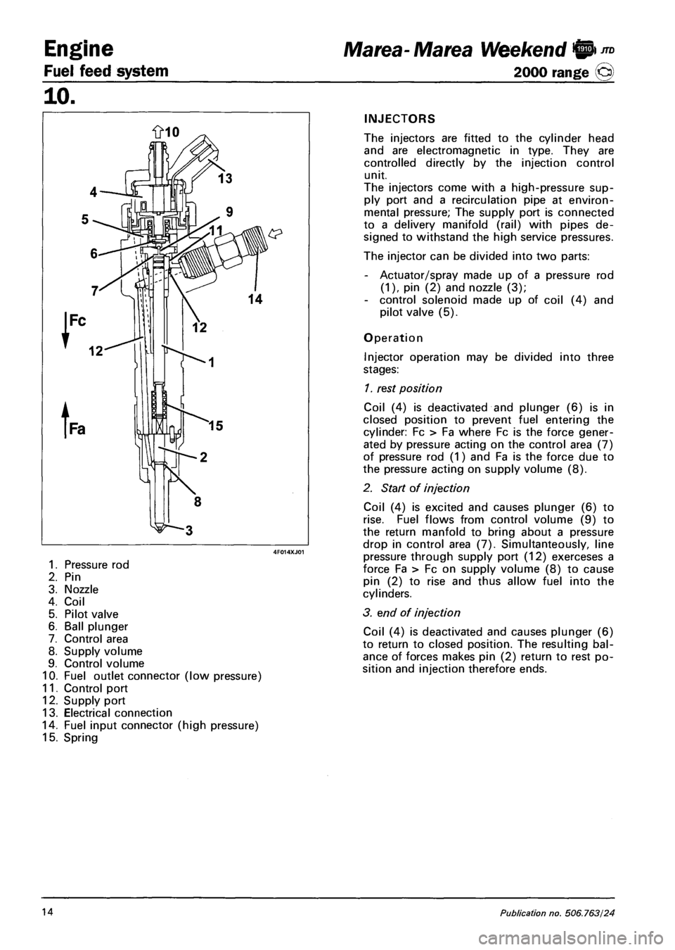
1. Pressure rod
2. Pin
3. Nozzle
4. Coil
5. Pilot valve
6. Ball plunger
7. Control area
8. Supply volume
9. Control volume
10. Fuel outlet connector (low pressure)
11. Control port
12. Supply port
13. Electrical connection
14. Fuel input connector (high pressure)
15. Spring
Marea- Marea Weekend 9 ™
2000 range (Q)
INJECTORS
The injectors are fitted to the cylinder head
and are electromagnetic in type. They are
controlled directly by the injection control
unit.
The injectors come with a high-pressure sup
ply port and a recirculation pipe at environ
mental pressure; The supply port is connected
to a delivery manifold (rail) with pipes de
signed to withstand the high service pressures.
The injector can be divided into two parts:
- Actuator/spray made up of a pressure rod
(1), pin (2) and nozzle (3);
- control solenoid made up of coil (4) and
pilot valve (5).
Operation
Injector operation may be divided into three
stages:
1. rest position
Coil (4) is deactivated and plunger (6) is in
closed position to prevent fuel entering the
cylinder: Fc > Fa where Fc is the force gener
ated by pressure acting on the control area (7)
of pressure rod (1) and Fa is the force due to
the pressure acting on supply volume (8).
2. Start of injection
Coil (4) is excited and causes plunger (6) to
rise. Fuel flows from control volume (9) to
the return manfold to bring about a pressure
drop in control area (7). Simultanteously, line
pressure through supply port (12) exerceses a
force Fa > Fc on supply volume (8) to cause
pin (2) to rise and thus allow fuel into the
cylinders.
3. end of injection
Coil (4) is deactivated and causes plunger (6)
to return to closed position. The resulting bal
ance of forces makes pin (2) return to rest po
sition and injection therefore ends.
14 Publication no. 506.763/24
Page 127 of 330
Auxiliary Units
Climate control
Marea-Marea Weekend
2000 range O
50
COMPRESSOR (1910 JTD)
The compressor fitted on this version is the SANDEN SD7V16 variable capacity type.
The capacity of the compressor varies starting from the maximum value (161.3 cm^/rev) and is gradually
reduced (up to 10.4 cm^/rev) according to the system load variations. - changed outside temperature
and/or humidity conditions or sharp variations in the engine load.
This solution is defined as "unlimited variable capacity".
The compressor is the alternating piston type: the variation in capacity is achieved by tilting the connect
ing rod holder plate with a consequent variation of the piston stroke: the movement of the plate is acti
vated by an internal regulation valve according to the balance of pressure upstream and downstream of
the compressor. In particular, a low intake pressure involves the shuttering of the compressor (reduced ca
pacity), whilst a high pressure involves operation at maximum power (maximum capacity).
7 6 4 3 2
5 9
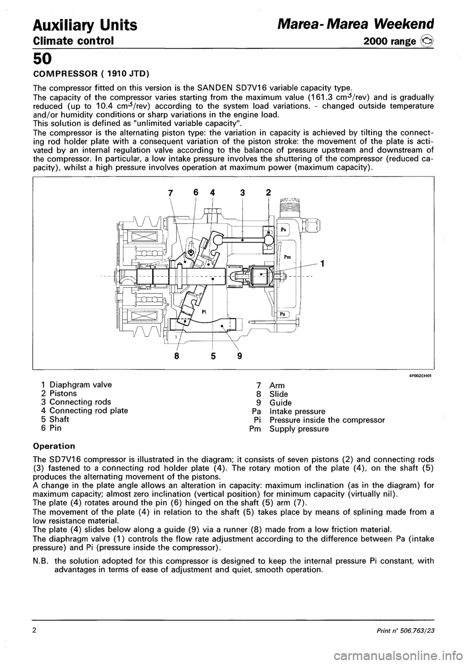
1 Diaphgram valve
2 Pistons
3 Connecting rods
4 Connecting rod plate
5 Shaft
6 Pin
7 Arm
8 Slide
9 Guide
Pa Intake pressure
Pi Pressure inside the compressor
Pm Supply pressure
Operation
The SD7V16 compressor is illustrated in the diagram; it consists of seven pistons (2) and connecting rods
(3) fastened to a connecting rod holder plate (4). The rotary motion of the plate (4), on the shaft (5)
produces the alternating movement of the pistons.
A change in the plate angle allows an alteration in capacity: maximum inclination (as in the diagram) for
maximum capacity; almost zero inclination (vertical position) for minimum capacity (virtually nil).
The plate (4) rotates around the pin (6) hinged on the shaft (5) arm (7).
The movement of the plate (4) in relation to the shaft (5) takes place by means of splining made from a
low resistance material.
The plate (4) slides below along a guide (9) via a runner (8) made from a low friction material.
The diaphragm valve (1) controls the flow rate adjustment according to the difference between Pa (intake
pressure) and Pi (pressure inside the compressor).
N.B. the solution adopted for this compressor is designed to keep the internal pressure Pi constant, with
advantages in terms of ease of adjustment and quiet, smooth operation.
2 Print n° 506.763/23
Page 128 of 330
Marea-Marea Weekend
2000 range ©)
Auxiliary Units
Climate control
50
COMPRESSOR ( 1998 engine)
The compressor fitted on this version is the SANDEN SD6V12 variable capacity type.
The capacity of the compressor varies starting from the maximum value (125.1 cnrfVrev) and is gradually
reduced (up to 6.2 cm /rev) according to the system load variations. - changed outside temperature
and/or humidity conditions or sharp variations in the engine load.
This solution is defined as "unlimited variable capacity".
The compressor is the alternating piston type: the variation in capacity is achieved by tilting the connect
ing rod holder plate with a consequent variation of the piston stroke: the movement of the plate is acti
vated by an internal regulation valve according to the balance of pressure upstream and downstream of
the compressor. In particular a low intake pressure involves the shuttering of the compressor (reduced ca
pacity), whilst a high pressure involves operation at maximum power (maximum capacity).
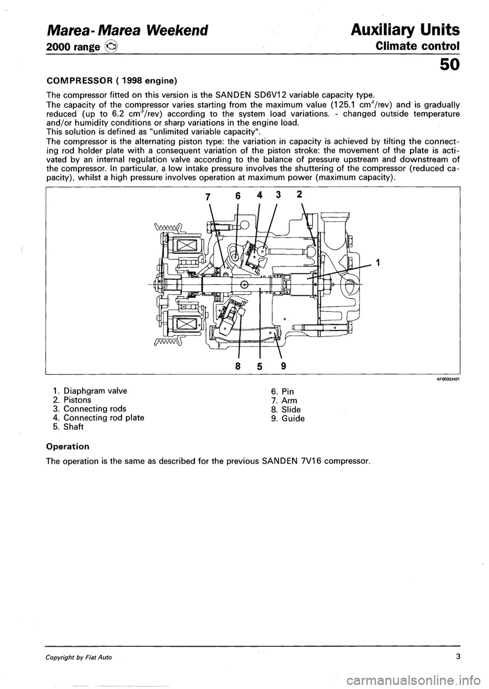
1. Diaphgram valve
2. Pistons
3. Connecting rods
4. Connecting rod plate
5. Shaft
6. Pin
7. Arm
8. Slide
9. Guide
Operation
The operation is the same as described for the previous SANDEN 7V16 compressor.
Copyright by Fiat Auto 3
Page 131 of 330
Marea- Marea Weekend
2000 range ©
Electrical equipment
Protection and security devices
55.
PROTECTION AND SAFETY DEVICES
All the vehicle supply lines were designed taking into account the most up-to-date directives in terms of
safety and protection, especially to prevent fires.
There are 2 types of protection:
- active protection, aims to reduce the causes of faults "at source"
- passive protection, aims to limit the effects of a fault as much as possible
The first category includes a carefully designed wiring layout with wires positioned and carefully anchored
on tracks that are repaired and protected if necessary.
The cables connected to the alternator and the motor were modified for this reason by adding protective
caps etc. A strengthened sheath was also introduced for some of the more exposed sections of wiring.
The passive protection includes all interventions to reduce faults due to high current (overload, short cir
cuit).
All system fuses were rated based on the nominal absorbtion of the loads activated at the same time, to
ensure intervention in cases of a clear short circuit.
The introduction of a box containing 4 maxifuses with other fuses connected on the outside means all
the supplies can be protected except for the cable that connects the battery to the starter motor and the
cable that connects the starter motor to the recharging alternator. These cables are therefore protected by a
strengthened supplementary sheath.
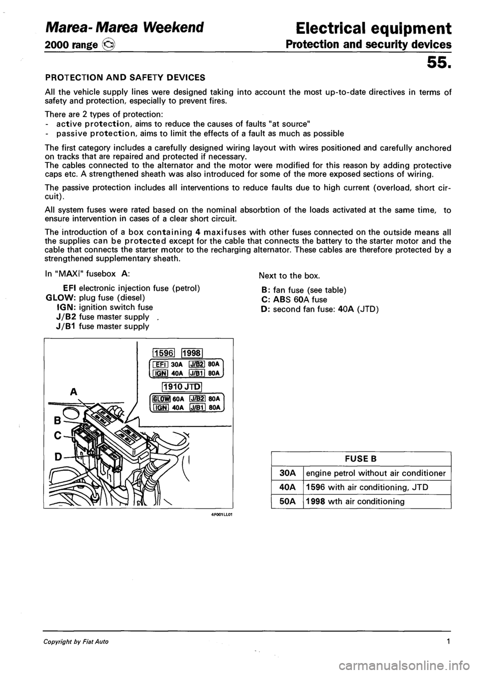
In "MAXI" fusebox A:
EFI electronic injection fuse (petrol)
GLOW: plug fuse (diesel)
IGN: ignition switch fuse
J/B2 fuse master supply .
J/B1 fuse master supply
Next to the box.
B: fan fuse (see table)
C: ABS 60A fuse
D: second fan fuse: 40A (JTD)
115961 1998
iFil 30A IJ/B21 BOA
fiGNl 4OA IJTBTI BOA
1910JTD
IGLOWl 60A P7B21 80A
MGNI 40A IJ/Bll 80A
FUSE B
30A engine petrol without air conditioner
40A 1596 with air conditioning, JTD
50A 1998 wth air conditioning
Copyright by Fiat Auto 1
Page 139 of 330
Marea-Marea Weekend Electrical equipment
2000 range (§) Location of components on the car
55.
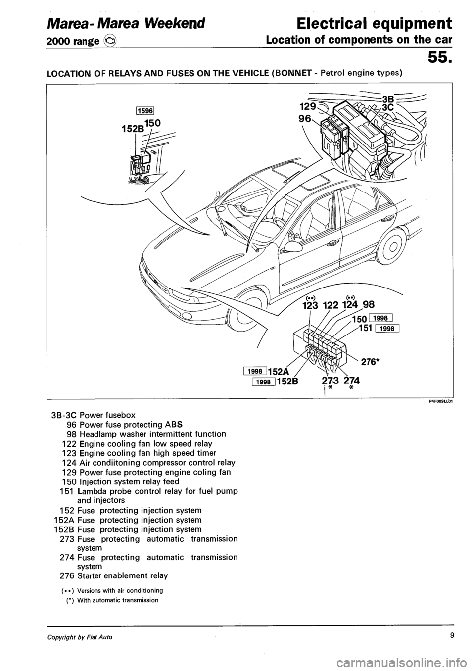
LOCATION OF RELAYS AND FUSES ON THE VEHICLE (BONNET - Petrol engine types)
Fi998l152B 273 274 i * *
3B-3C Power fusebox
96 Power fuse protecting ABS
98 Headlamp washer intermittent function
122 Engine cooling fan low speed relay
123 Engine cooling fan high speed timer
124 Air condiitoning compressor control relay
129 Power fuse protecting engine coling fan
150 Injection system relay feed
151 Lambda probe control relay for fuel pump
and injectors
152 Fuse protecting injection system
152A Fuse protecting injection system
152B Fuse protecting injection system
273 Fuse protecting automatic transmission
system
274 Fuse protecting automatic transmission
system
276 Starter enablement relay
(••) Versions with air conditioning
(*) With automatic transmission
Copyright by Fiat Auto 9
Page 186 of 330
Marea-Marea Weekend Electrical equipment
2000 range (§) Wiring diagrams
55.
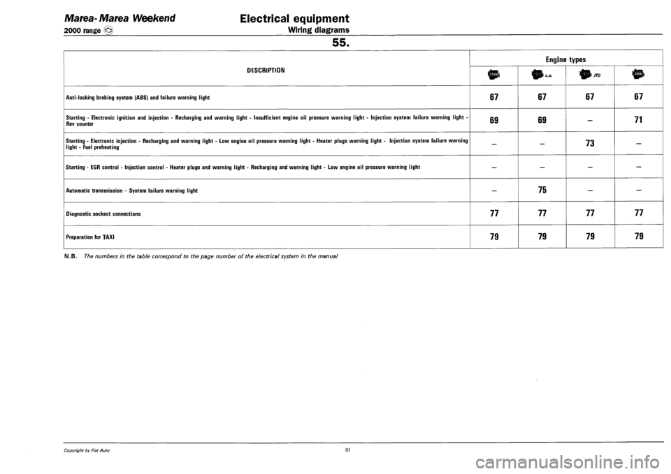
DESCRIPTION
Engine types
DESCRIPTION 10i 0) c.a. 01/70
ANTI-LOCKING BRAKING SYSTEM (ABS) AND FAILURE WARNING LIGHT 67 67 67 67
STARTING - ELECTRONIC IGNITION AND INJECTION - RECHARGING AND WARNING LIGHT - INSUFFICIENT ENGINE OIL PRESSURE WARNING LIGHT - INJECTION SYSTEM FAILURE WARNING LIGHT -
REV COUNTER 69 69 — 71
STARTING - ELECTRONIC INJECTION - RECHARGING AND WARNING LIGHT - LOW ENGINE OIL PRESSURE WARNING LIGHT - HEATER PLUGS WARNING LIGHT - INJECTION SYSTEM FAILURE WARNING
LIGHT - FUEL PREHEATING — — 73 —
STARTING - EGR CONTROL - INJECTION CONTROL - HEATER PLUGS AND WARNING LIGHT - RECHARGING AND WARNING LIGHT - LOW ENGINE OIL PRESSURE WARNING LIGHT — — — —
AUTOMATIC TRANSMISSION - SYSTEM FAILURE WARNING LIGHT — 75 — —
DIAGNOSTIC SOCKECT CONNECTIONS 77 77 77 77
PREPARATION FOR TAXI 79 79 79 79
FM.B. The numbers in the table correspond to the page number of the electrical system in the manual
Copyright by Fiat Auto III
Page 255 of 330
Marea-Marea Weekend
2000 range ©
Electrical equipment
Wiring diagrams
55.
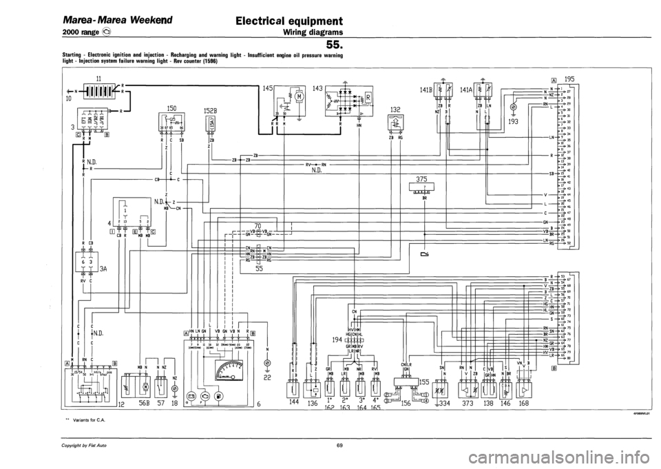
Starting - Electronic ignition and injection - Recharging and warning light - Insufficient engine oil pressure warning
light - Injection system failure warning light - Rev counter (1596)
11
N «
10 -•miliums
XX XX
l-H
h §
3 R —I
'jj it Itr
150
E1TT R M
rt
30 87 85 8£
i N.D,
f-R-
152B
R C SB
Z
p, <: in
ZB
n i
T m 2 13 5 2
CB-
N,D,
c
•i-c
141B
132 ZB
NZ
m>— MBN—CN
CB R MB MB
RV C
}N,D,
RN C
J I -|- -|i r—pji I 15/54 I Irrt/a J pos s-taz
M
-IB-
IE HN LN GN
50 Irrt
,11
MB N N NZ
I NZ
12 56B 57 18
-ZB--ZB-
70 i VB-R-VB 1—
P- — GN--Q--GN
-CN
r—RG-
RN -CN-
RV—»—RN
N,D,
Z7T
ZB HN-
-RG-
55
VB GN VB N R i
7 9 11 18 12 19(m> 9(>«) 23 22 N
22
rl.l
(J
H..I
ZB RG
141A
375
BR
CN
HV HM HG
194 4
GR
CN
MB
HL
P RV ILR
GR MB LR
NRI
CN LR
-31.
N
ZB LN
L
193
U
MB RVI MB GN SNl RN
144 136 1' 2* 3* 4° 0X3==^^ lJ=c® I334 373 138 146 168
155
1
16? 163 164 165
ZB VB
GR N BR
VN
r
"N 111 L
L^
H 195
•N--I
- N
-RN-
-NZ--2
L ->
3
4
5
6
7
8
LN-M
10
11
12
13
14
15
16
17
R -•
-SB--
- V¬
- L -
- C -
-GN-
-VB B -•
-BR--
-LN-RG-
-0 27 3 28
<• 29
30
31
32
33
34
35
36
37
38
39
40
41
42
43 18 —(• 44 19 —(- 45 20 —(• 46 21 —O 47 22 —(• 48 23 49 24 -«• 50 25 . 51 26 —(• 52
R ->
-ZB--
• L — f>
-HG-C--
-HL-HN-
-RN-
-BR
-NZ
-HM GR--
-HV
53 67 54 -O 68 55 69 56 > 70 57 71 58 —«• 72
, 73 -> 60
75
SN+ii76 63 —«• 77 64 , -6-78 VB-r> &5 6-79 LR--«
Variants for C.A.
Copyright by Fiat Auto 69
Page 256 of 330
Electrical equipment
Component location
Marea-Marea Weekend
2000 range ©
55.
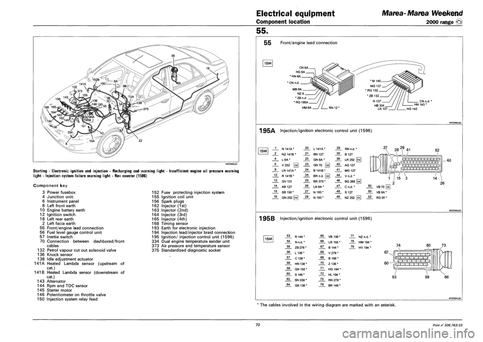
Starting - Electronic ignition and injection - Recharging and warning light
light - Injection system failure warning light - Rev counter (1596)
Insufficient engine oil pressure warning
Component key
3 Power fusebox
4 Junction unit:
6 Instrument panel
8 Left front earth
10 Engine battery earth
12 Ignition switch
18 Left rear earth
2 Left facia earth
55 Front/engine lead connection
56 Fuel level gauge control unit
57 Inertia switch
70 Connection between dashborad/front
cables
132 Petrol vapour cut out solenoid valve
136 Knock sensor
138 Idle adjustment actuator
141A Heated Lambda sensor (upstream of
cat.)
141 B Heated Lambda sensor (downstream of
cat.)
143 Alternator
144 Rpm and TDC sensor
145 Starter motor
146 Potentiometer on throttle valve
150 Injection system relay feed
152 Fuse protecting injection system
155 Ignition coil unit
156 Spark plugs
162 Injector (1st)
163 Injector (2nd)
164 Injector (3rd)
165 Injector (4th)
168 Timing sensor
193 Earth for electronic injection
194 Injection lead/injector braid connection
195 Ignition/ injection control unit (1596)
334 Dual engine temperature sender unit
373 Air pressure and temperature sensor
375 Standardized diagnostic socket
55 Front/engine lead connection
1596
CN6A.
HG6A.
* HN 6A
1 CN n.d.
MB6A.
NZ8_
* ZB n.d
*RG195A_
HM6A
CN n.d. HN 143 *
HG 142
1 95A Injection/ignition electronic control unit (1596)
1596 1 N 141A* 20 L 141A* 29 RN n.d. *
2 NZ141B* 21 BN 127 35 B 127
4 L6A* 23 GN 6A* 36 LR252 [c*
5 V252 0 23 GN70 0 40 AG 127
9 LN 141A* 24 B141B* 41 MG 127
12 R 141B* 25 BR n.d. 0 44 Vn.d.*
13 GV131 25 BR 375 * 46 BG 268 [a
14 AB 127 26 LN6A* 47 C n.d. *
15 SB 150* 27 N 193* 48 S 127
16 GN 252 [cal 28 N 193* 49 NZ252
27 282,9 41 52
O I I I I I I -r-r-r'n , , r'l -r-
rrrri '/ 1 1 1 1 1 1 1 1 1 1 1 \1 L/-HJ 'A i I I i i ,I
40
1 95B Injection/ignition electronic control unit (1596)
1596 53 R144* 65 VB 138* JL. NZn.d. *
54 N n.d. * 66 LR 155 * _ZL HM194*
55 ZB 278 * 67 B 144* _7JL HV194*
56 L136* 68 V278*
57 C138* 69 B 168*
58 HN 138* 70 Z136*
59 GN 155 * 71 HG 194 *
60 S 146* 72 HL194*
62 SN 339 * 75 RN 278 *
64 GR138* 76 BR 146 *
74
67-Jf Mill i i r r-l I I I
60-
IE
L -j |l
53 59
The cables involved in the wiring diagram are marked with an asterisk.
70 Print n° 506.763/23
Page 257 of 330
Marea-Marea Weekend
2000 range (§)
Electrical equipment
Wiring diagrams
55.
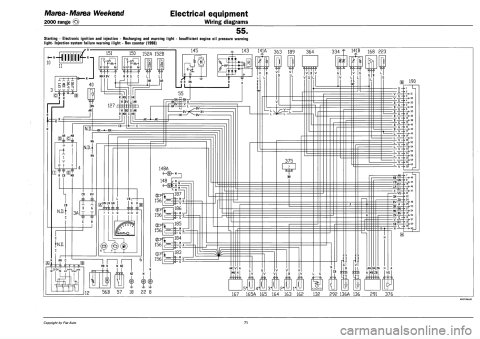
STARTING - ELECTRONIC IGNITION AND INJECTION - RECHARGING AND WARNING LIGHT - INSUFFICIENT ENGINE OIL PRESSURE WARNING
LIGHT- INJECTION SYSTEM FAILURE WARNING ILIGHT - REV COUNTER (1998)
^—hi 11111
168 223
56B 57 18 22 8 167 165A 165 164 163 162 132 292 136A 136 291 376
Copyright by Fiat Auto 71
Page 258 of 330
Electrical equipment
Component location
Marea-Marea Weekend
2000 range ®
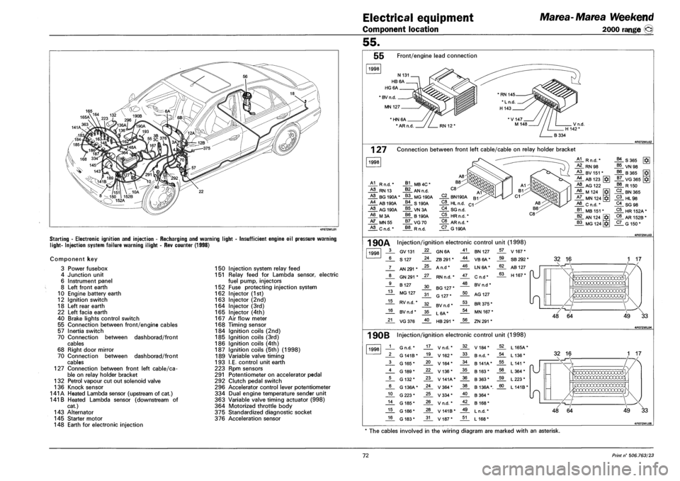
Starting - Electronic ignition and injection - Recharging and warning light
light- Injection system failure warning ilight - Rev counter (1998)
Insufficient engine oil pressure warning
Component key
3 Power fusebox
4 Junction unit
6 Instrument panel
8 Left front earth
10 Engine battery earth
12 Ignition switch
18 Left rear earth
22 Left facia earth
40 Brake lights control switch
55 Connection between front/engine cables
57 Inertia switch
70 Connection between dashborad/front
cables
68 Right door mirror
70 Connection between dashborad/front
cables
127 Connection between front left cable/ca
ble on relay holder bracket
132 Petrol vapour cut out solenoid valve
136 Knock sensor
141A Heated Lambda sensor (upstream of cat.)
141 B Heated Lambda sensor (downstream of
cat.)
143 Alternator
145 Starter motor
148 Earth for electronic injection
150 Injection system relay feed
151 Relay feed for Lambda sensor, electric
fuel pump, injectors
152 Fuse protecting injection system
162 Injector (1st)
163 Injector (2nd)
164 Injector (3rd)
165 Injector (4th)
167 Air flow meter
168 Timing sensor
184 Ignition coils (2nd)
185 Ignition coils (3rd)
186 Ignition coils (4th)
187 Ignition coils (5th) (1998)
189 Variable valve timing
193 I.E. control unit earth
223 Rpm sensors
291 Potentiometer on accelerator pedal
292 Clutch pedal switch
296 Accelerator control lever potentiometer
334 Dual engine temperature sender unit
363 Variable valve timing actuator (998)
364 Motorized throttle body
375 Standardized diagnostic socket
376 Acceleration sensor
55.
55 Front/engine lead connection
1998
* BV n.d
MN 127
' HN 6A
* AR n.d
1 27 Connection between front left cable/cable on relay holder bracket
1998
A1 R n.d.'
HL RN 13
HL BG 190A
A4 AB 190A
HL AG 190A
A6 M3A
HL MN55
HL C n.d. *
J*L MB 4C *
J*L AN n.d.
_§§_ MG 190A
_§£. S 190A
VN3A
66 B190A
_§7_ VG70
R n.d.
C2 BN190A
_2L HL n.d.
C4_ SG n.d.
C5 HRn.fi.'
C6 AR n.d. *
_5L G 190A
A1 R n.d. * B4 S365
HL RN98 B5 VN 98 A3 BV 151 * B6 B365 A4 AB 123 J7_ VG365 J*I
HL AG 122 B8 R 150 A6 M 124 C2 BN365 A7 MN 124 C3 HL98 A8 Cn.d.* C4 SG 98 B1 MB 151 * C5 HR152A* B2 AN 124 C6 AR 152B *
B3 MG 124 C7 G 150*
1 90A Injection/ignition electronic control unit (1998)
1998 3 GV131 22 GN6A 41 BN 127 57 V 167*
6 S 127 24 ZB 291 * 44 VB6A* 59 SB 292 *
7 AN 291 * 25 A n.d* 46 LN6A* 62 AB 127
"U 8 GN 291 * 27 RN n.d. * 47 Cn.d* 63 H 167* "U
9 B 127 30 BG 127 * 48 BV n.d *
13 MG 127 31 G 127* 50 AG 127
15 RV n.d. * 32 BV n.d * 53 BR 375 *
16 BV n.d * 35 L6A* 54 MN 167 *
21 VG376 40 HB 291 * 56 ZN 291 *
32 16
49 33
1 90B Injection/ignition electronic control unit (1998)
1998 1 G n.d. * 17 V n.d. * 32 V184* 52 L165A*
2 G 141B* 19 V162* 33 B n.d. * 54 L 136*
3 G 165* 20 V164* 34 B 141A* 55 L 141 *
4 G 189* 22 V136* 35 B 163* 58 L364*
5 G 132* 23 V141A* 36 B363* 59 L223*
6 G 136A* 24 V364* 38 B 136A*. 60 L141B*
10 G223* 25 V334* 40 B364*
14 G 185* 26 V n.d. * 42 B 168*
15 G 186* 28 V 141B* 49 L n.d. *
16 G 183* 31 V187* 51 L 168*
49 33
* The cables involved in the wiring diagram are marked with an asterisk.
72 Print n° 506.763/23