fuse diagram FIAT MAREA 2001 1.G Workshop Manual
[x] Cancel search | Manufacturer: FIAT, Model Year: 2001, Model line: MAREA, Model: FIAT MAREA 2001 1.GPages: 330
Page 95 of 330
Marea- Marea Weekend 9 ™
2000 range ©) Fuel feed system
Engine
10.
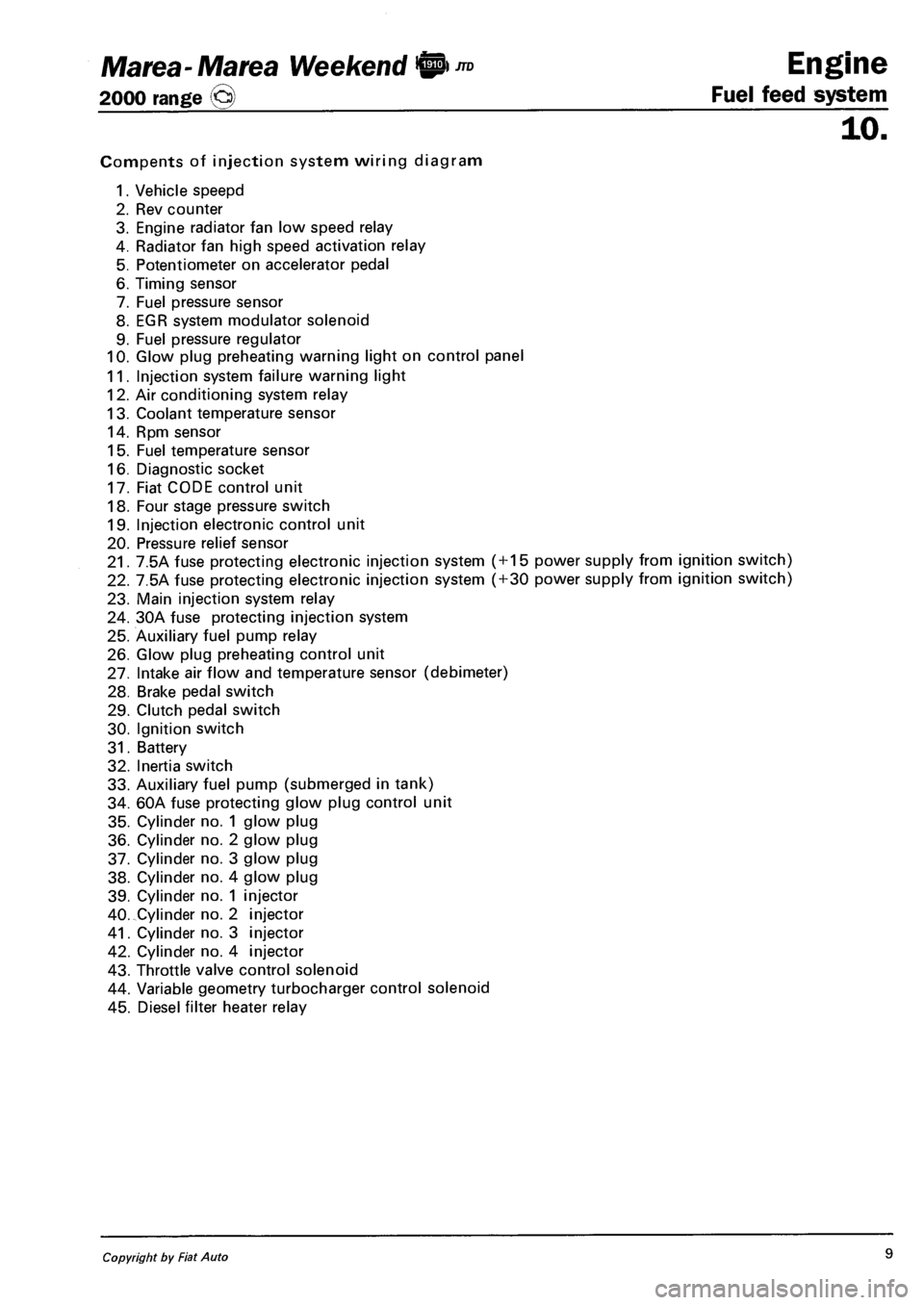
Compents of injection system wiring diagram
1. Vehicle speepd
2. Rev counter
3. Engine radiator fan low speed relay
4. Radiator fan high speed activation relay
5. Potentiometer on accelerator pedal
6. Timing sensor
7. Fuel pressure sensor
8. EGR system modulator solenoid
9. Fuel pressure regulator
10. Glow plug preheating warning light on control panel
11. Injection system failure warning light
12. Air conditioning system relay
13. Coolant temperature sensor
14. Rpm sensor
15. Fuel temperature sensor
16. Diagnostic socket
17. Fiat CODE control unit
18. Four stage pressure switch
19. Injection electronic control unit
20. Pressure relief sensor
21. 7.5A fuse protecting electronic injection system ( + 15 power supply from ignition switch)
22. 7.5A fuse protecting electronic injection system ( + 30 power supply from ignition switch)
23. Main injection system relay
24. 30A fuse protecting injection system
25. Auxiliary fuel pump relay
26. Glow plug preheating control unit
27. Intake air flow and temperature sensor (debimeter)
28. Brake pedal switch
29. Clutch pedal switch
30. Ignition switch
31. Battery
32. Inertia switch
33. Auxiliary fuel pump (submerged in tank)
34. 60A fuse protecting glow plug control unit
35. Cylinder no. 1 glow plug
36. Cylinder no. 2 glow plug
37. Cylinder no. 3 glow plug
38. Cylinder no. 4 glow plug
39. Cylinder no. 1 injector
40. Cylinder no. 2 injector
41. Cylinder no. 3 injector
42. Cylinder no. 4 injector
43. Throttle valve control solenoid
44. Variable geometry turbocharger control solenoid
45. Diesel filter heater relay
Copyright by Fiat Auto 9
Page 132 of 330
Electrical equipment
Protection and safety devices
Marea- Marea Weekend
2000 range ©)
55.
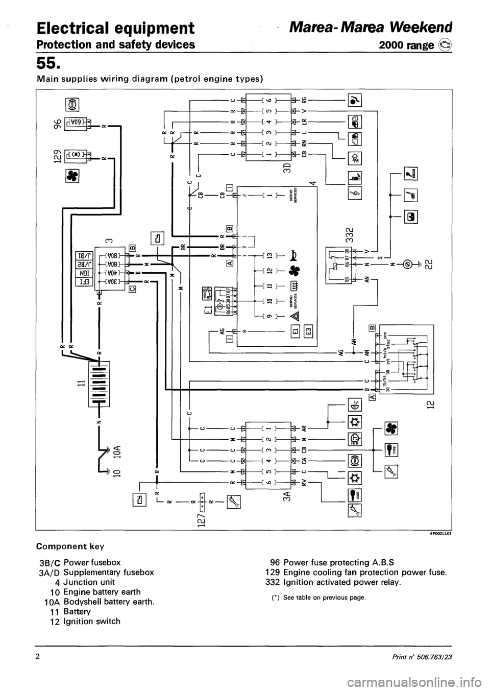
Main supplies wiring diagram (petrol engine types)
Component key
3B/C Power fusebox
3A/D Supplementary fusebox
4 Junction unit
10 Engine battery earth
10A Bodyshell battery earth.
11 Battery
12 Ignition switch
96 Power fuse protecting A.B.S
129 Engine cooling fan protection power fuse.
332 Ignition activated power relay.
(*) See table on previous page.
2 Print n° 506.763/23
Page 133 of 330
Marea- Marea Weekend
2000 range ©)
Electrical equipment
Protection and safety devices
55.
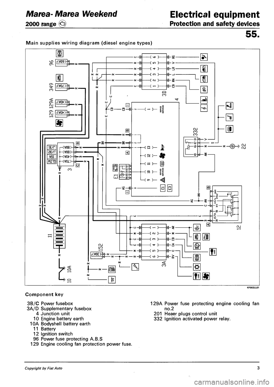
Main supplies wiring diagram (diesel engine types)
Component key
3B/C Power fusebox
3A/D Supplementary fusebox
4 Junction unit
10 Engine battery earth
10A Bodyshell battery earth
11 Battery
12 Ignition switch
96 Power fuse protecting A.B.S
129 Engine cooling fan protection power fuse.
129A Power fuse protecting engine cooling fan
no.2
201 Heaer plugs control unit
332 Ignition activated power relay.
Copyright by Fiat Auto 3
Page 134 of 330
Electrical equipment
Junction unit
Marea-Marea Weekend
2000 range ©
55.
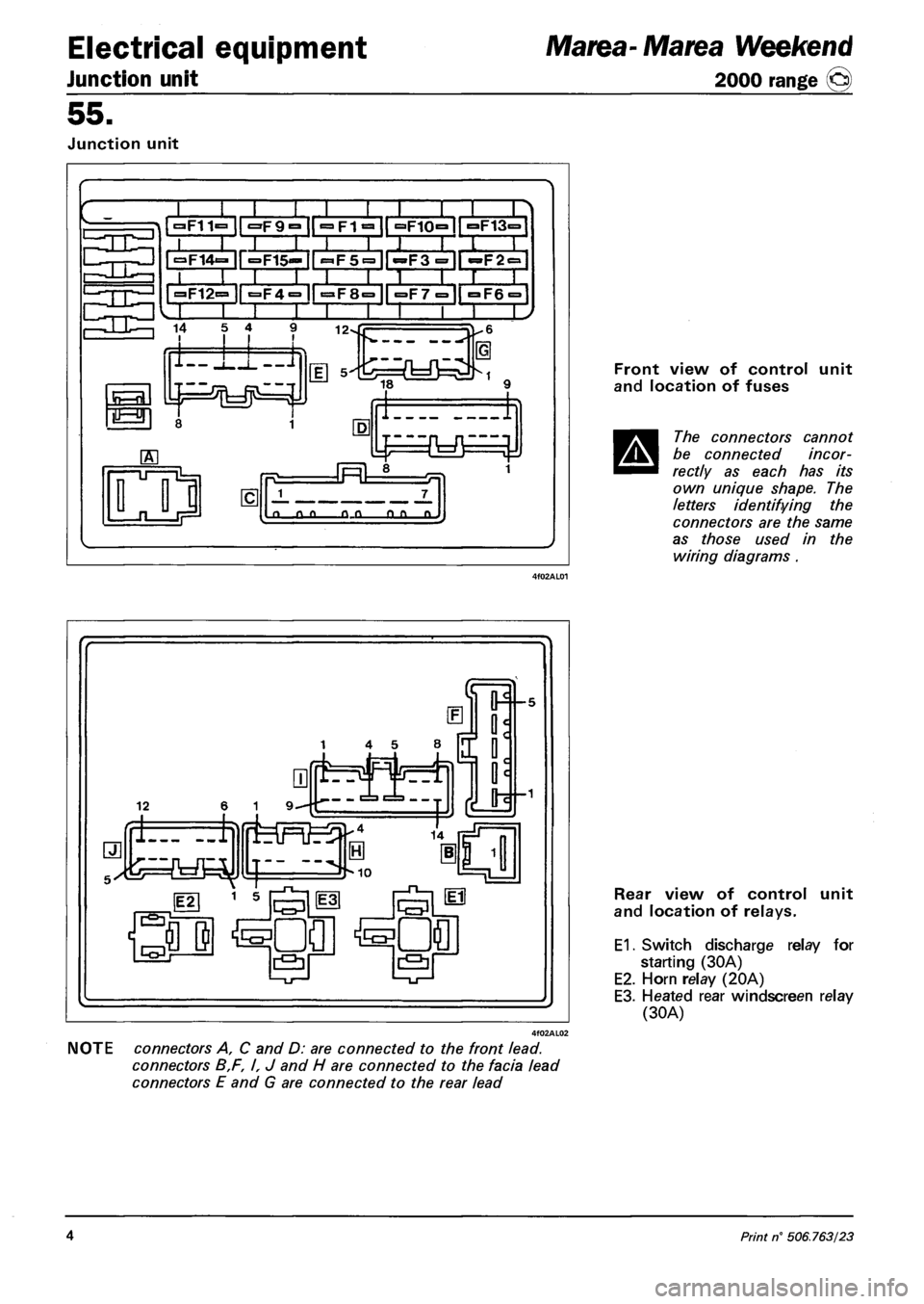
Junction unit
»F11=
~T~ II l;
•F9° |["^FT^1| °F10°ir°F13=
| ^14=- ir=F15«=- II
»F12=
SLHHItHia r i i i •
3F4= ir^F8=1l =F7="|| °F6 = 1
I I I I I 1 I '
14 5 4 12-
lor
1-11-J
I 1
J 7_
a o_o o_o OLD n.
Front view of control unit
and location of fuses
The connectors cannot
be connected incor
rectly as each has its
own unique shape. The
letters identifying the
connectors are the same
as those used in the
wiring diagrams .
NOTE connectors A, C and D: are connected to the front lead.
connectors B,F, I, J and H are connected to the facia lead
connectors E and G are connected to the rear lead
Rear view of control unit
and location of relays.
E1. Switch discharge relay for
starting (30A)
E2. Horn relay (20A)
E3. Heated rear windscreen relay
(30A)
4 Print n° 506.763/23
Page 188 of 330
Electrical equipment
Wiring diagrams
Marea- Marea Weekend
2000 range ©
55.
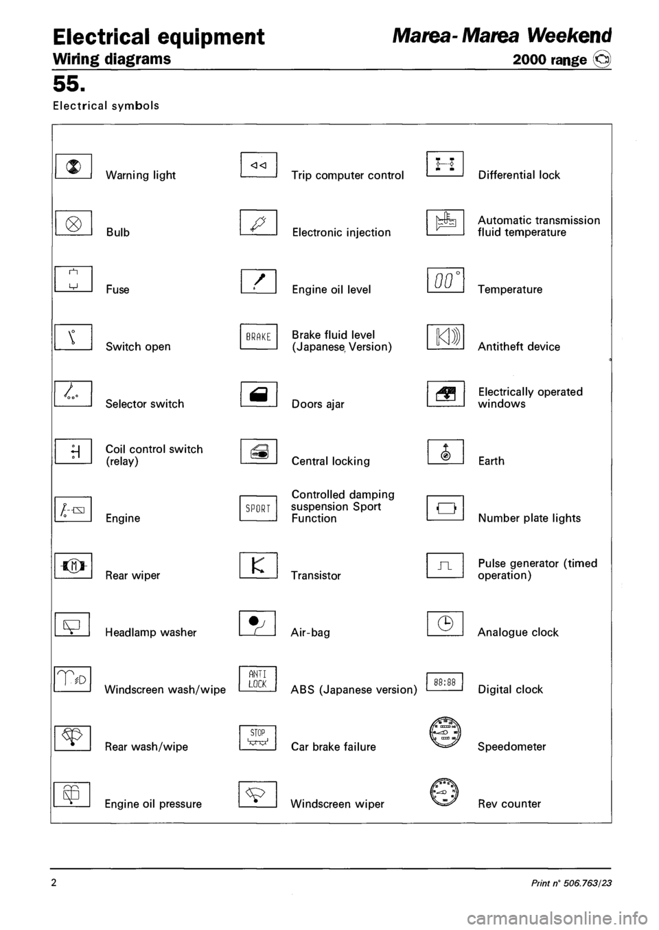
Electrical symbols
Warning light
Bulb
/--txi
T
Fuse
Switch open
Selector switch
Coil control switch
(relay)
Engine
Rear wiper
Headlamp washer
Windscreen wash/wipe
Rear wash/wipe
Engine oil pressure
BRAKE
SPORT
K
ANT I LOCK
STOP
Trip computer control
Electronic injection
Engine oil level
Brake fluid level
(Japanese, Version)
Doors ajar
Central locking
Controlled damping
suspension Sport
Function
Transistor
Air-bag
ABS (Japanese version)
Car brake failure
Windscreen wiper
H Differential lock
Automatic transmission
fluid temperature
00' Temperature
Antitheft device
Electrically operated
windows
Earth
Number plate lights
Pulse generator (timed
operation)
Analogue clock
Digital clock
Speedometer
Rev counter
2 Print n° 506.763/23
Page 192 of 330
4F006ML01
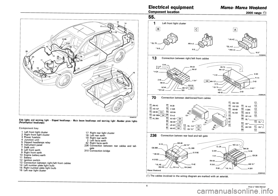
SIDE LIGHTS AND WARNING LIGHT - DIPPED HEADLAMPS - MAIN BEAM HEADLAMPS AND WARNING LIGHT -NUMBER PLATE LIQHTS (POLYELHPTICAL HEADLAMPS) r »
Component key
1 Left front light cluster
2 Right front light cluster
3 Power fusebox
4 Junction unit:
5 Dipped headlamps relay
6 Instrument panel
7 Stalk unit
8 Left front earth
9 Right front earth
10 Engine battery earth
11 Battery
12 Ignition switch
13 Connection between right/left front cables
14 Left number plate light bulb
15 Right number plate light bulb
16 Left rear light cluster
17 Right rear light cluster
18 Left rear earth
19 Right rear earth
2 Left facia earth
42 Right facia earth
236 Connection between rear cables and tail
gate
310 Connection bridge
Electrical equipment
Component location
Marea-Marea Weekend
2000 range (§)
55.
Left front light cluster
B
'GL70
N8'
1 3 Connection between right/left front cables
•H2A
NZ44
* GV n.d.
70 Connection between dashborad/front cables
A1
— RN 4C
— VG 127
B1 M29
^1 VB 55 | 1242
A3
— V328
11 AG6A
VB 195A | 1581 |B4 GN D
^1 HL 26A 11 AV 4D * I 1581
?! AB 4D"
11 LR 4C f
1581
1242
1Z_ AN4C| 1581
RN 120
VG 120
^1 VB6B
£1 HL120
B1 M n.d.
11 V28A
11 AG 41
11 LB n.d.
21
C2_
21
21
C5
B5 GL"
21 GL n.d.
2L GV13*
11 GV*
!T_ AN 120
B8
C6 GL •
2Z_ GV*J
21 P4F808NO4
236 Connection betwen rear lead and tail-gate
CB 28B
CB 26
* HL 4E
RG 4G
Marea Weekend
(*) The cables involved in the wiring diagram are marked with an asterisk.
6 Print n° 506.763/23
Page 194 of 330
Electrical equipment
Component location
Marea-Marea Weekend
2000 range ©
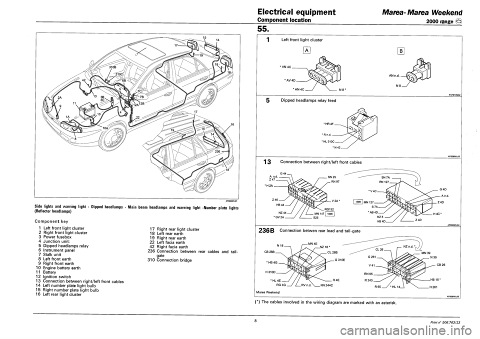
SIDE LIGHTS AND WARNING LIGHT - DIPPED HEADLAMPS - MAIN BEAM HEADLAMPS AND WARNING LIGHT -NUMBER PLATE LIGHTS
(REFLECTOR HEADLAMPS)
Component key
1 Left front light cluster
2 Right front light cluster
3 Power fusebox
4 Junction unit:
5 Dipped headlamps relay
6 Instrument panel
7 Stalk unit
8 Left front earth
9 Right front earth
10 Engine battery earth
11 Battery
12 Ignition switch
13 Connection between right/left front cables
14 Left number plate light bulb
15 Right number plate light bulb
16 Left rear light cluster
17 Right rear light cluster
18 Left rear earth
19 Right rear earth
22 Left facia earth
42 Right facia earth
236 Connection between rear cables and tail
gate
310 Connection bridge
55.
1 Left front light cluster
*VN 4C
' AV4D
B
AN n.d.
N8 *HN4C N8'
Dipped headlamps relay feed
' HR4F
1 3 Connection between right/left front cables
•H2A
236B Connection betwen rear lead and tail-gate
CB 28B
H4C*
CB 26
Marea Weekend
(*) The cables involved in the wiring diagram are marked with an asterisk.
8 Print n° 506.763/23
Page 196 of 330
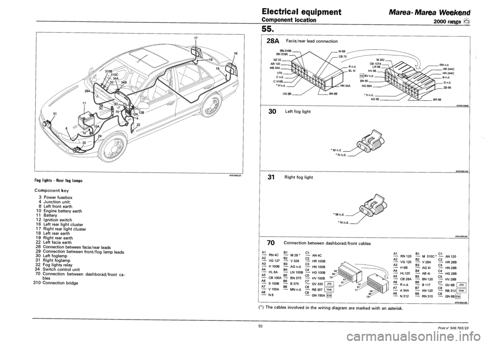
FOG LIGHTS - REAR FOG LAMPS
Component key
3 Power fusebox
4 Junction unit:
8 Left front earth
10 Engine battery earth
11 Battery
12 Ignition switch
16 Left rear light cluster
17 Right rear light cluster
18 Left rear earth
19 Right rear earth
22 Left facia earth
28 Connection between facia/rear leads
29 Connection between front/fog lamp leads
30 Left foglamp
31 Right foglamp
32 Fog lights relay
34 Switch control unit
70 Connection between dashborad/front cables
310 Connection bridge
Electrical equipment
Component location
Marea- Ma tea Weekend
2000 range ©
55.
28A Facia/rear lead connection
RN 31 OB RN 31 OA
* H n.d
HG 6B
BR 66
30 Left fog light
31 Right fog light
' M n.d.
* N n.d.
70 Connection between dashborad/front cables
A1 B1 C1 — RN4C — M29* — AN4C A2 B2 C2 — VG127 — V328 — HR 100B A3 B3 C3 — H100B — AG n.d. — HN 100B A4 B4 C4 — HL6A — LN 100B — HG 100B A5 B5 C5 - CB 100A — BN 375 — HV 100B A6 B6 C7 , — S100B — B375 — GV335 JTD A7 B8 C8 F= — V100A — MN n.d. — RB 307 TAXI A8 C8 " N 8 — GN 195A H
A1 — RN 120 A2 — VG120 A3 — H6B A4 — HL120 A5 — CB28A A6 — Rn.d. A7 — A34A A8 — N312
B1 C1 — M 310C* — AN B2 — V28A B3 — AG4I B4 — AB4I B5 — BN 120 B6 — B117 B7 — AN 120 B8 — RN315
C2 — HR C3 — HN C4 — HG C5 — HV C7 — GV C8 — RB C8 — GN
120
28B
28B
28B
28B
6B I JTD
312 TAXI
6Bps|
4F010ML0S
(*) The cables involved in the wiring diagram are marked with an asterisk.
10 Print n° 506.763/23
Page 198 of 330
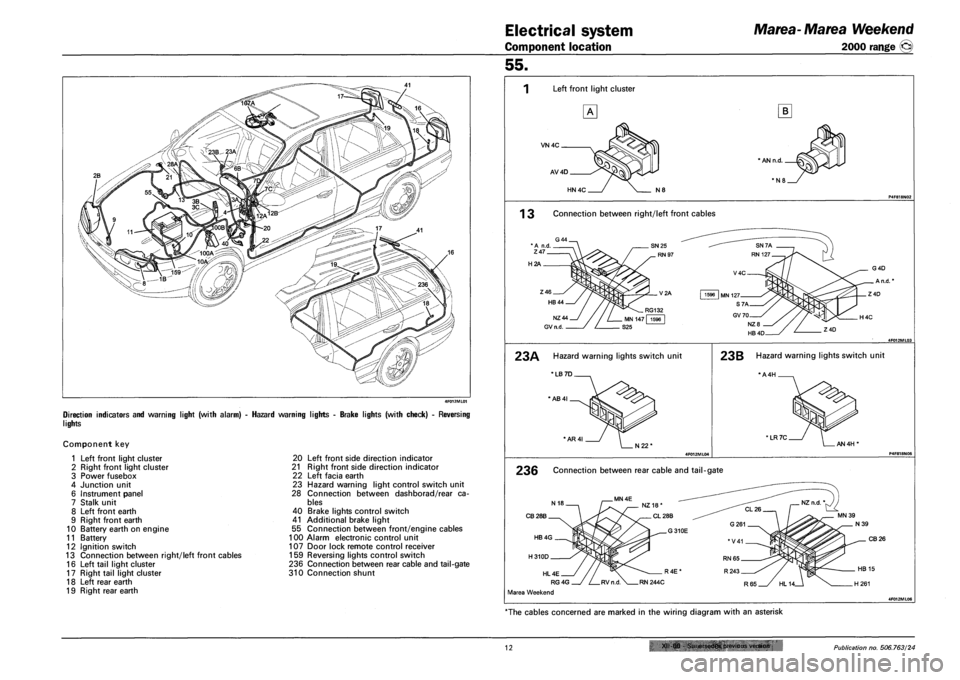
Electrical system
Component location
Marea- Marea Weekend
2000 range ©
DIRECTION INDICATORS AND WARNING LIGHT (WITH ALARM)
LIGHTS
Component key
1 Left front light cluster
2 Right front light cluster
3 Power fusebox
4 Junction unit
6 Instrument panel
7 Stalk unit
8 Left front earth
9 Right front earth
10 Battery earth on engine
11 Battery
12 Ignition switch
13 Connection between right/left front cables
16 Left tail light cluster
17 Right tail light cluster
18 Left rear earth
19 Right rear earth
HAZARD WARNING LIGHTS - BRAKE LIGHTS (WITH CHECK) - REVERSING
20 Left front side direction indicator
21 Right front side direction indicator
22 Left facia earth
23 Hazard warning light control switch unit
28 Connection between dashborad/rear ca
bles
40 Brake lights control switch
41 Additional brake light
55 Connection between front/engine cables
100 Alarm electronic control unit
107 Door lock remote control receiver
159 Reversing lights control switch
236 Connection between rear cable and tail-gate
310 Connection shunt
55.
Left front light cluster
VN4C
AV4D
B
* AN n.d.
HN4C N8
1 3 Connection between right/left front cables
H2A
23A Hazard warning lights switch unit
'LB 7D
*AB4I
'AR4I
23B Hazard warning lights switch unit
*A4H .
' LR 7C AN 4H'
236 Connection between rear cable and tail-gate
CB28B
CB 26
HL 4E
RG4G
Marea Weekend
"The cables concerned are marked in the wiring diagram with an asterisk
12 XII 00 &jiii!-»cdes OMtfiuii.-. vtrsiun Publication no. 506.763/24
Page 200 of 330
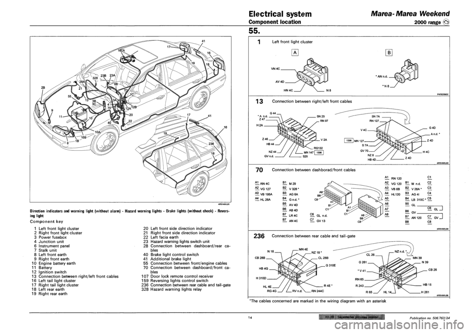
Electrical system
Component location
Marea- Marea Weekend
2000 range ©
DIRECTION INDICATORS AND WARNING LIGHT (WITHOUT ALARM) - HAZARD WARNING
ING LIGHT
Component key
IGHTS - BRAKE LIGHTS (WITHOUT CHECK) - REVERS-
1 Left front light cluster
2 Right front light cluster
3 Power fusebox
4 Junction unit
6 Instrument panel
7 Stalk unit
8 Left front earth
9 Right front earth
10 Engine battery earth
11 Battery
12 Ignition switch
13 Connection between right/left front cables
16 Left tail light cluster
17 Right tail light cluster
18 Left rear earth
19 Right rear earth
20 Left front side direction indicator
21 Right front side direction indicator
22 Left facia earth
23 Hazard warning lights switch unit
28 Connection between dashboard/rear ca
bles
40 Brake light control switch
41 Additional brake light
55 Connection between front/engine cables
70 Connection between dashboard/front ca
bles
107 Door lock remote control receiver
159 Reversing lights control switch
236 Connection between rear cable and tail-gate
328 Hazard warning lights relay
55.
Left front light cluster
VN4C
AV4D
B
HN 4C
1 3 Connection between right/left front cables
H2A
70 Connection between dashborad/front cables
A1 RN4C B1 M29 A2 VG 127 B2 V328* A3 VB 195A B3 AG 6A A4 HL26A B4 G n.d. * B5 AV4D B6 AB4D B7 LR4C B7 AN4C
EL GL n.d.
EL GV13
5§^LT]
El GV
1L AN 120 EL GV J B8 C8
236 Connection between rear cable and tail-gate
CB28B
CB26
HL4E
RG4G 4F014ML05
"The cables concerned are marked in the wiring diagram with an asterisk
14 XII-98 - Supersedes previous version Publication no. 506.763/24